Downloaded 28 times
![INTERNSHIP REPORT AKSHATHA B A
Dept. of Civil Engineering, KVGCE, Sullia (2016-17) Page 6
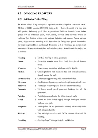
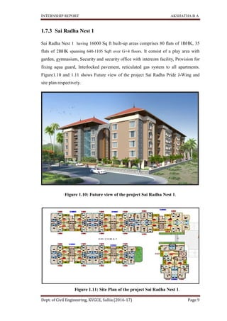
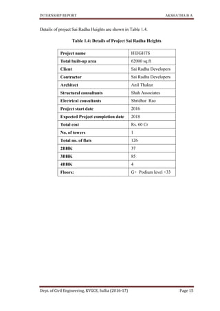
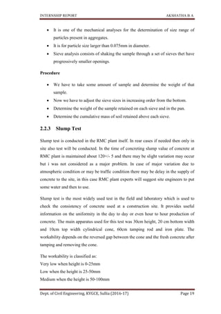
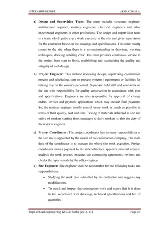
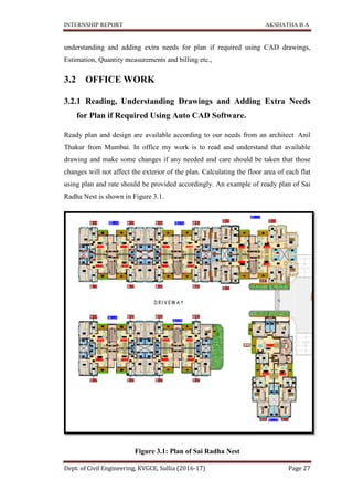
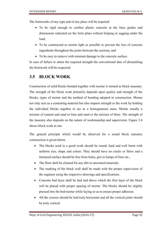
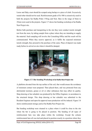
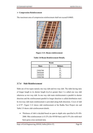
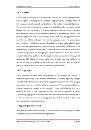
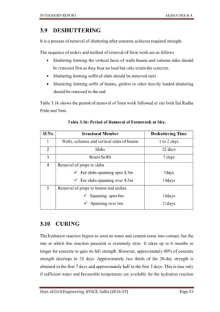
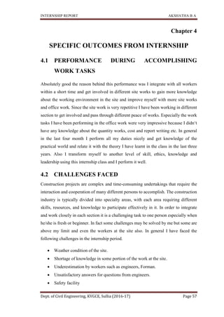
Details of project Pride J Wing are shown in Table 1.1.
Table 1.1: Details of Project Sai Radha Pride J Wing.
Project name SAI RADHA PRIDE J-WING
Total built-up area 5972 Sqft
Client Sai Radha Developers
Contractor Sai Radha Developers
Architect Anil Thakur
Structural consultants Shah Associates
Electrical consultants Shridhar Rao
Project start date 2011
Expected Project completion date 2016
Total cost Rs. 17,44,00,000
No. of towers 1[J]
Total no. of flats 56
2BHK 14
3BHK 42
Floors: Basement +G+14
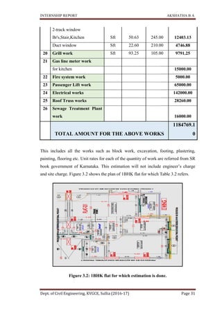
Figure 1.7: Future view of the project Sai Radha Pride J-Wing.](https://image.slidesharecdn.com/internshipreportakku-200331053545/85/Internship-Report-Construction-Site-and-Office-Work-6-320.jpg)
![INTERNSHIP REPORT
Dept. of Civil Engineering, KVGCE, Sullia (2016
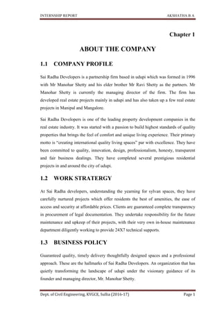
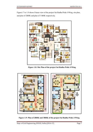
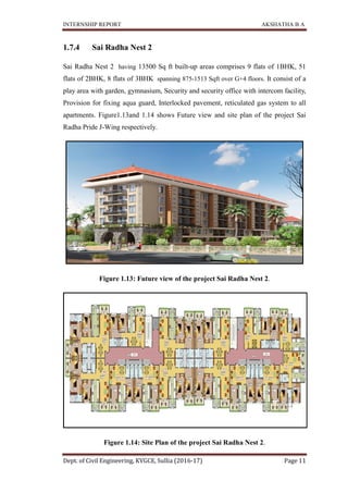
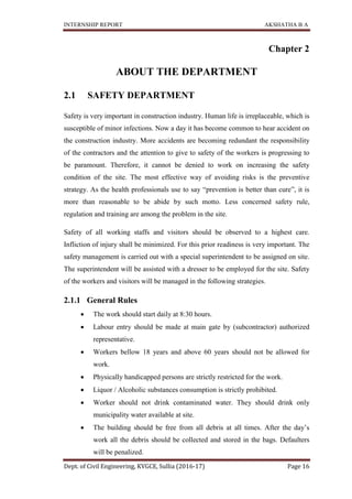
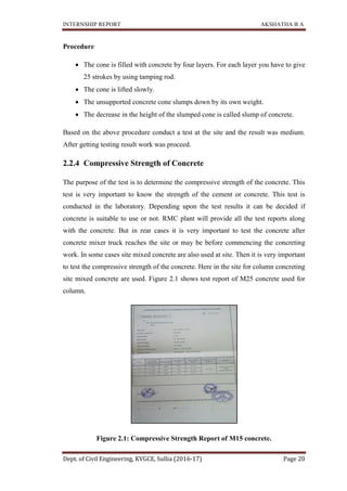
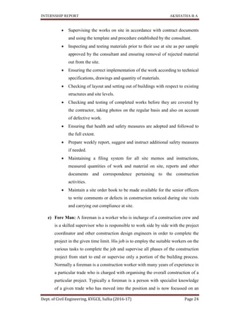
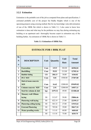
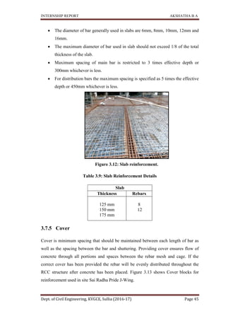
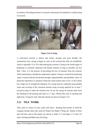
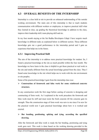
Figure 1.12 shows plan
shown in Table 1.2.
Figure 1.12: Plan of
Table
Project name
Total area
Total built
Client
Contractor
Architect
Structural consultants
Electrical consultants
Project start date
Expected Project completion date
Total cost
No. of towers
Total no. of flats
1BHK
2BHK
Floors:
INTERNSHIP REPORT
Dept. of Civil Engineering, KVGCE, Sullia (2016-17)
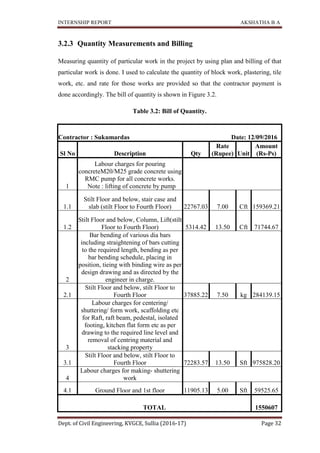
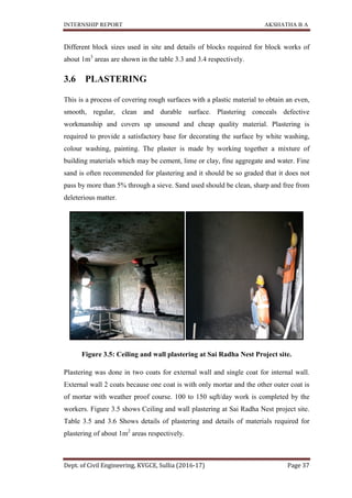
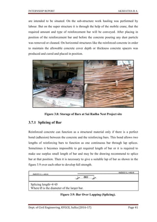
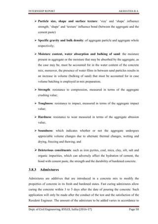
plan of 1BHK and 2 BHK. Details of project Sai Radha
: Plan of 1BHK and 2BHK of the project Sai Radha
able 1.2: Details of Project Sai Radha Nest 1
Project name SAI RADHA NEST 1
Total area 1.02 acres
Total built-up area 16000 Sq ft
Sai Radha Developers
Contractor Sai Radha Developers
Anil Thakur
Structural consultants Shah Associates
Electrical consultants Shridhar Rao
Project start date June 2015
Expected Project completion date Dec 2016
Total cost
No. of towers 6 [A, B, C, D, E & F]
Total no. of flats 115
80
35
G+4
AKSHATHA B A
Page 10
Details of project Sai Radha Nest 1 are
of the project Sai Radha Nest 1
Nest 1
NEST 1
Sai Radha Developers
Sai Radha Developers
Shah Associates
6 [A, B, C, D, E & F]](https://image.slidesharecdn.com/internshipreportakku-200331053545/85/Internship-Report-Construction-Site-and-Office-Work-10-320.jpg)
![INTERNSHIP REPORT
Dept. of Civil Engineering, KVGCE, Sullia (2016
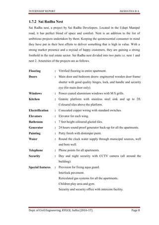
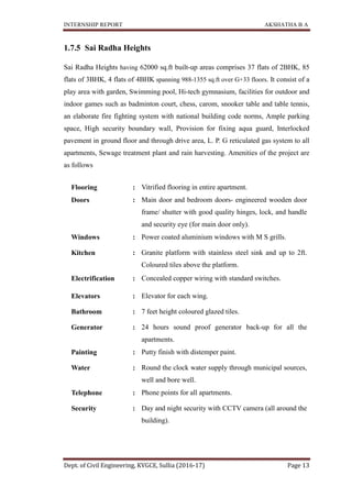
Details of project Sai Radha Nest
1BHK, 2 BHK and 3 BHK
Table
Project name
Total built
Client
Contractor
Architect
Structural consultants
Electrical consultants
Project start date
Expected Project completion date
Total cost
No. of towers
Total no. of flats
1BHK
2BHK
3BHK
Floors:
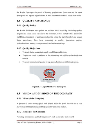
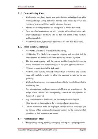
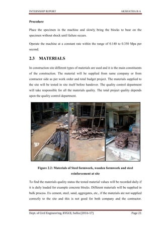
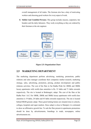
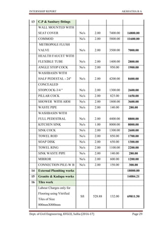
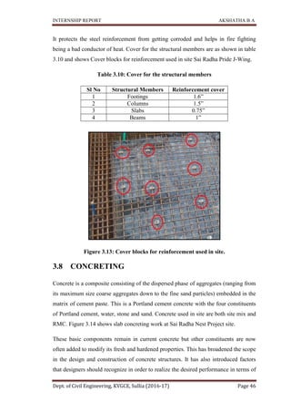
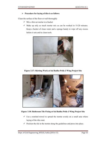
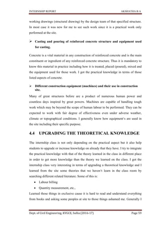
Figure 1.15: Plan of
INTERNSHIP REPORT
Dept. of Civil Engineering, KVGCE, Sullia (2016-17)
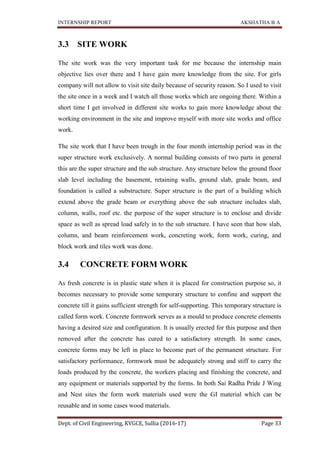
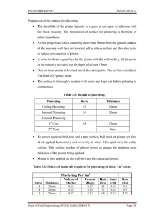
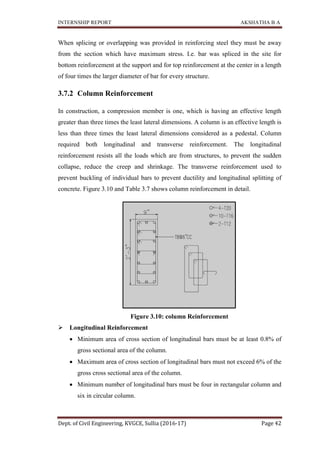
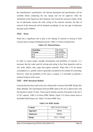
Details of project Sai Radha Nest 2 are shown in Table 1.3. Figure 1.15 shows
3 BHK of the project Sai Radha Nest 2.
Table 1.3: Details of Project Sai Radha Nest 2
Project name SAI RADHA NEST 2
Total built-up area 13500 Sq ft
Sai Radha Developers
Contractor Sai Radha Developers
Anil Thakur
Structural consultants Shah Associates
Electrical consultants Shridhar Rao
Project start date Jan- 2016
Expected Project completion date Dec 2016
Total cost 11,74,32,000
No. of towers 2 [G & H]
Total no. of flats 68
9
51
8
G+4
: Plan of 1BHK, 2BHK & 3BHK of the project Sai Radha
AKSHATHA B A
Page 12
Figure 1.15 shows plan of
2
NEST 2
Sai Radha Developers
Sai Radha Developers
Shah Associates
of the project Sai Radha Nest 2](https://image.slidesharecdn.com/internshipreportakku-200331053545/85/Internship-Report-Construction-Site-and-Office-Work-12-320.jpg)


Sai Radha Developers is a real estate developer based in Udupi, India that has completed several residential projects and has ongoing projects. It aims to provide high-quality housing to middle-income families at affordable prices. Their ongoing projects include Sai Radha Pride J Wing, a residential tower with 56 units, and Sai Radha Nest 1 & 2, two residential complexes with a total of 115 and 68 units respectively. The company focuses on timely delivery, quality construction, and customer satisfaction.