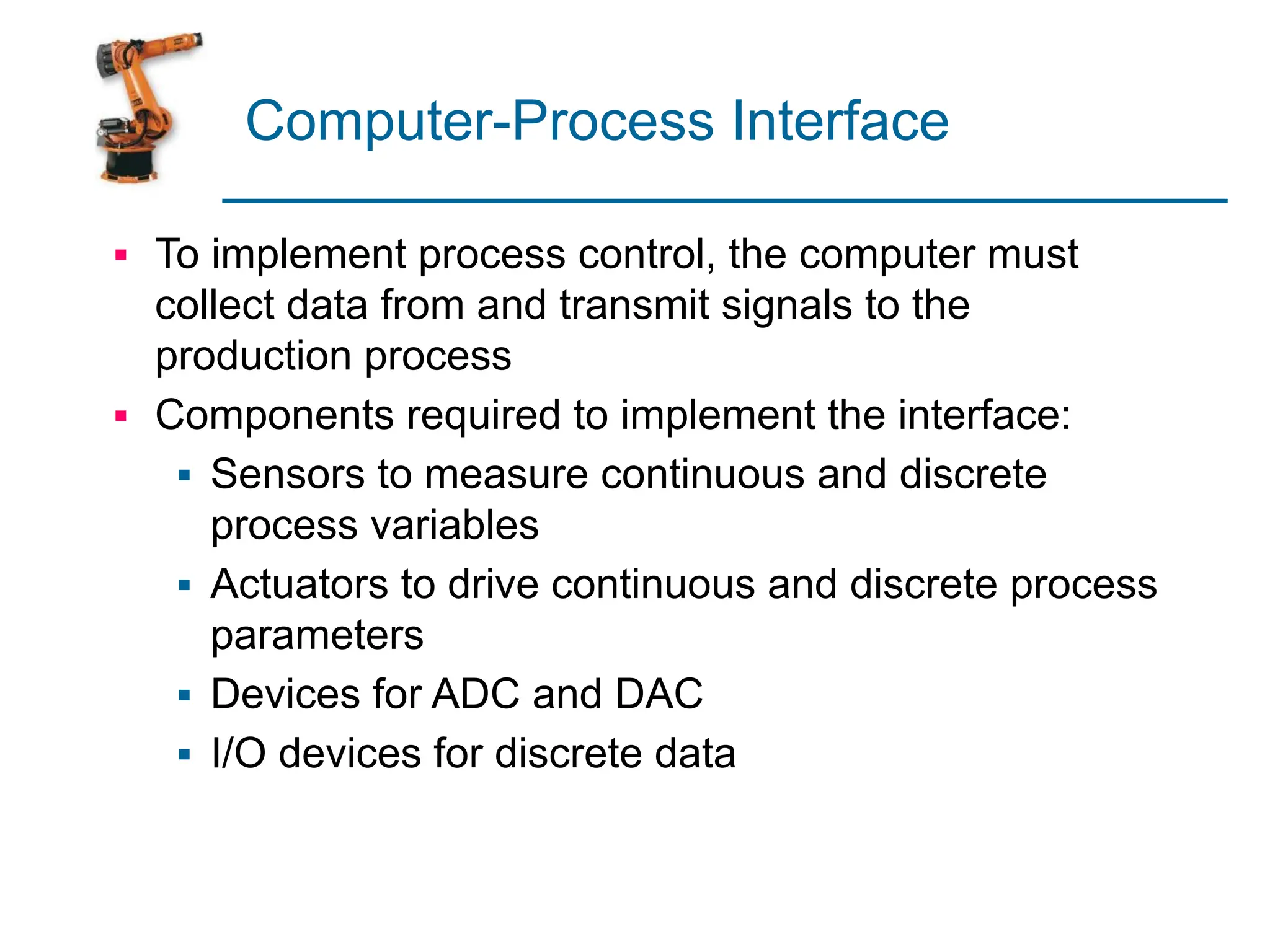
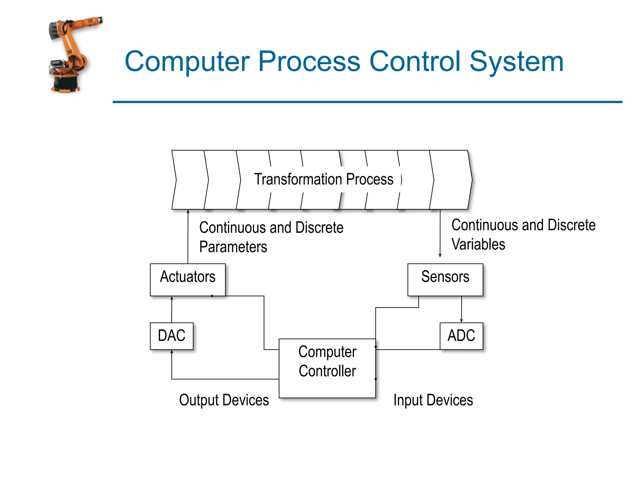
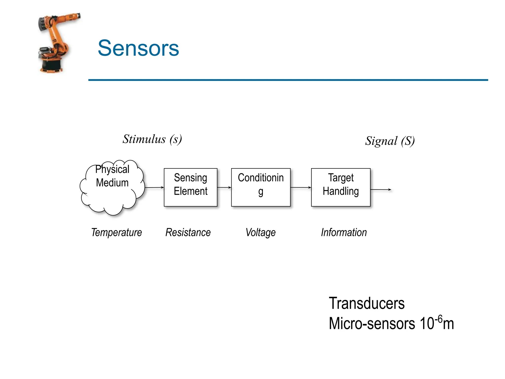
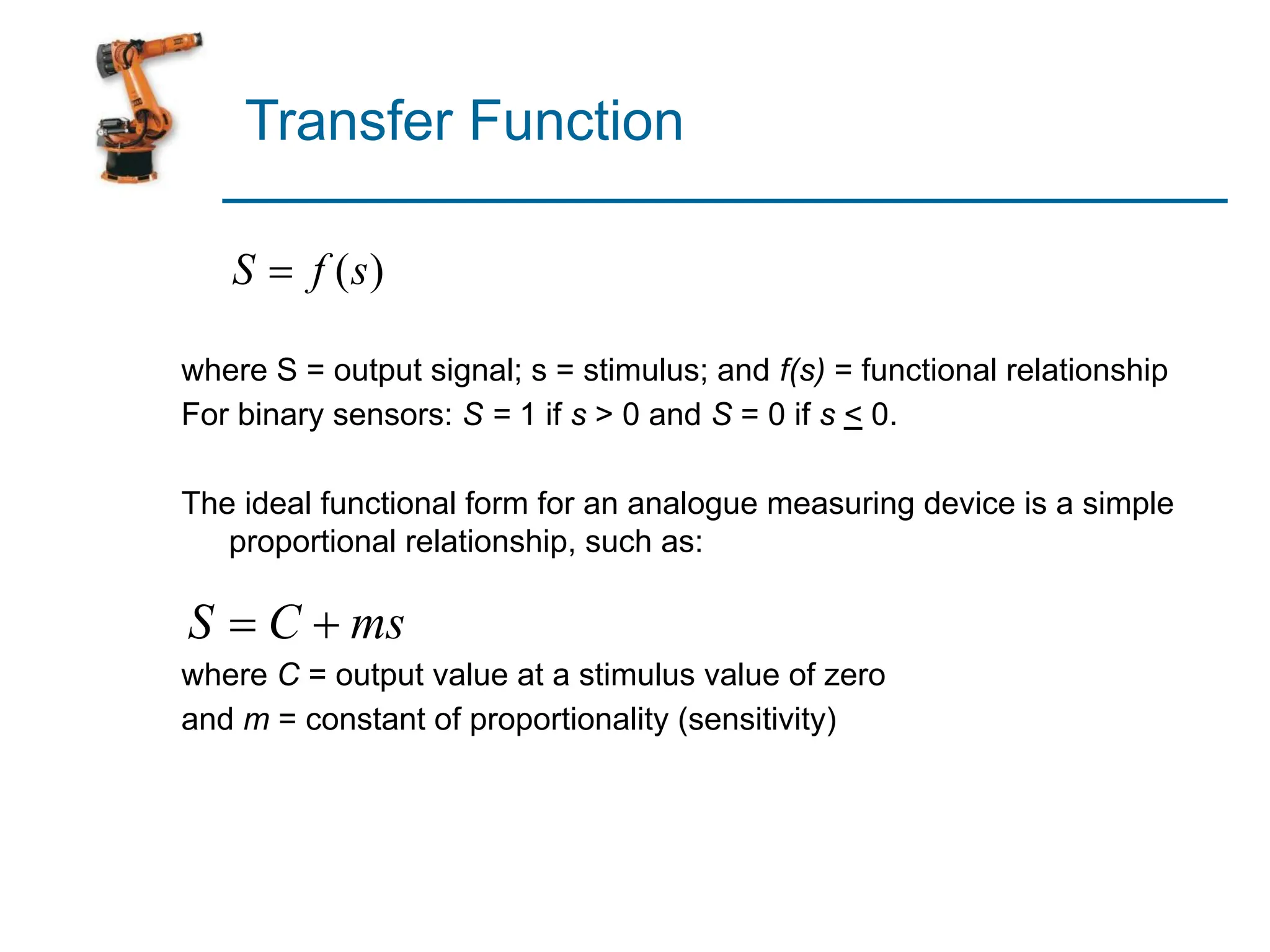
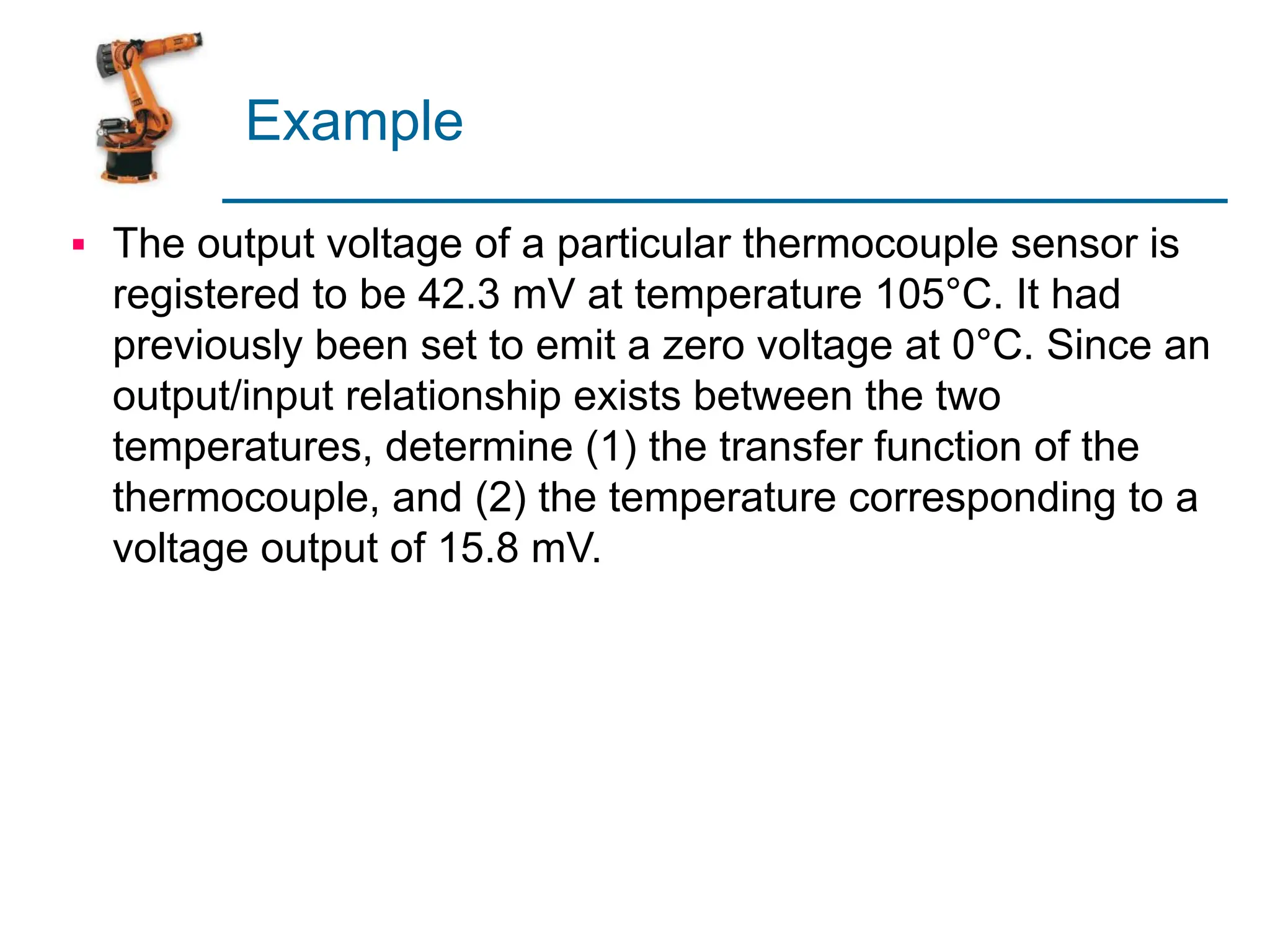
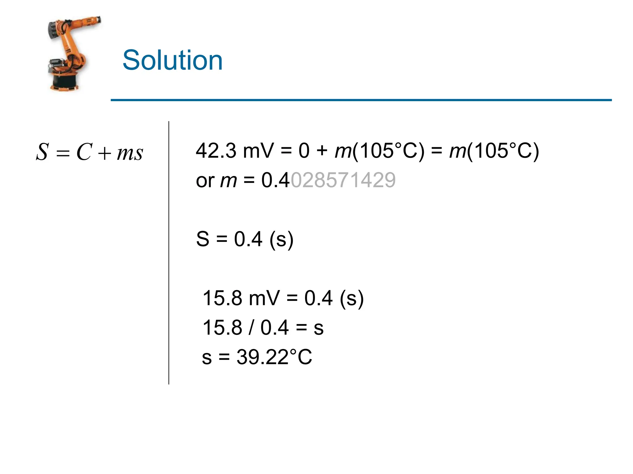
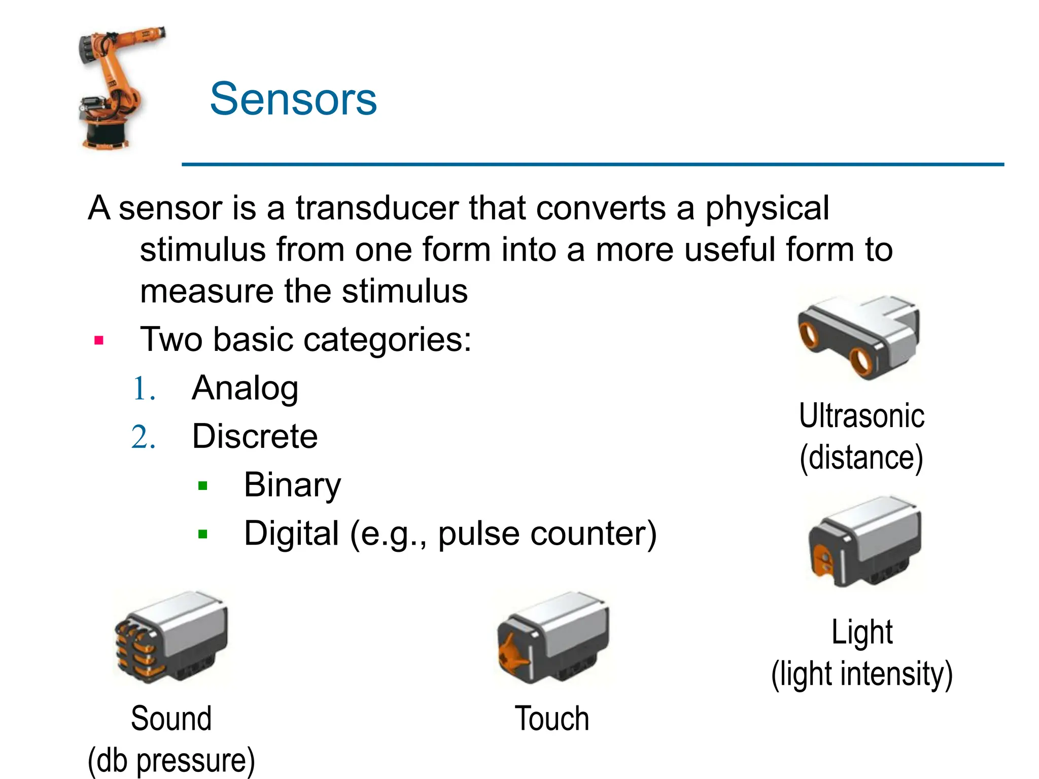
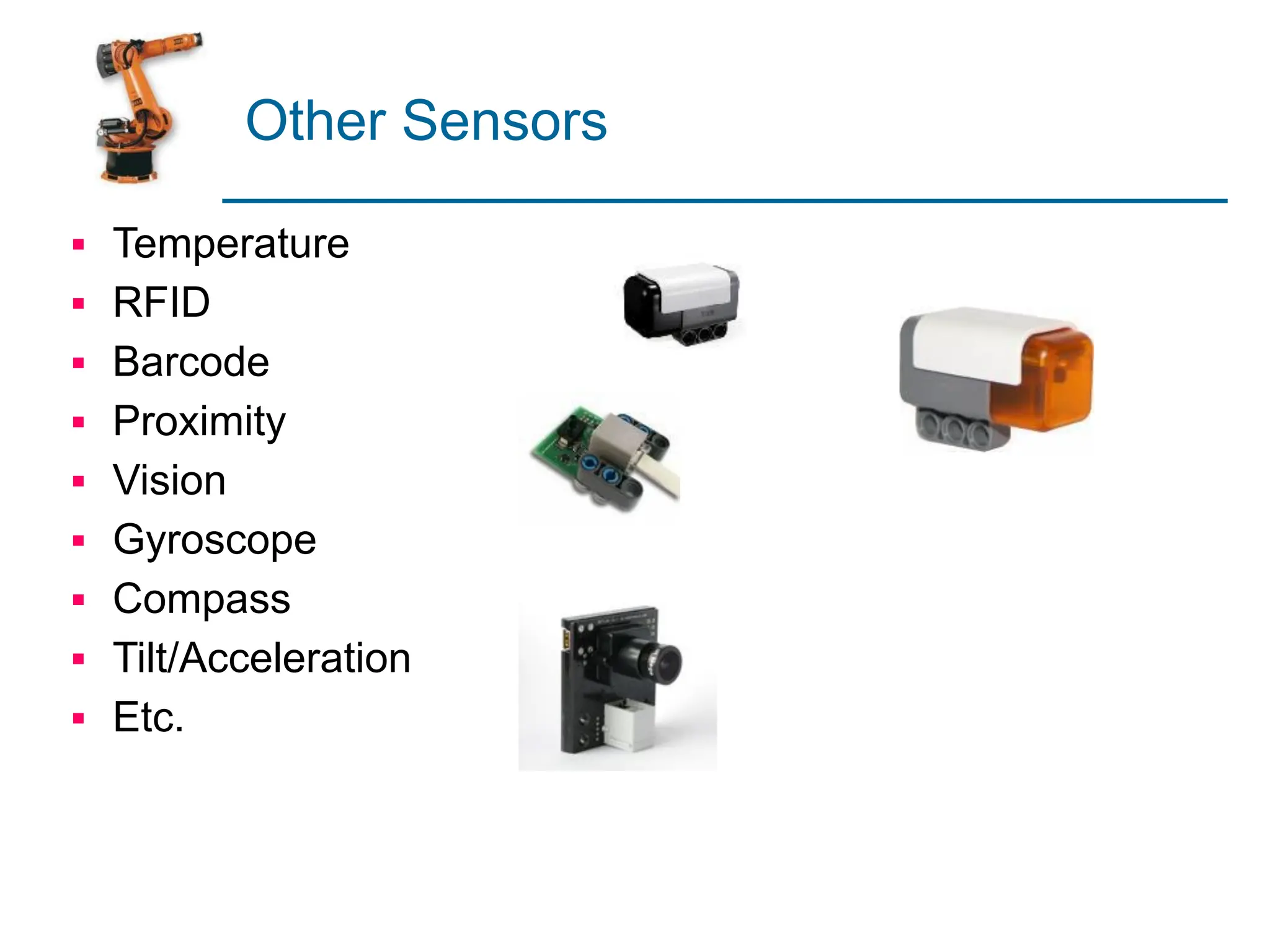
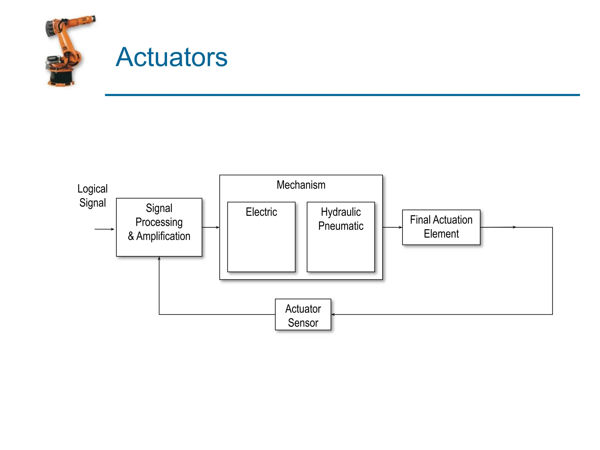
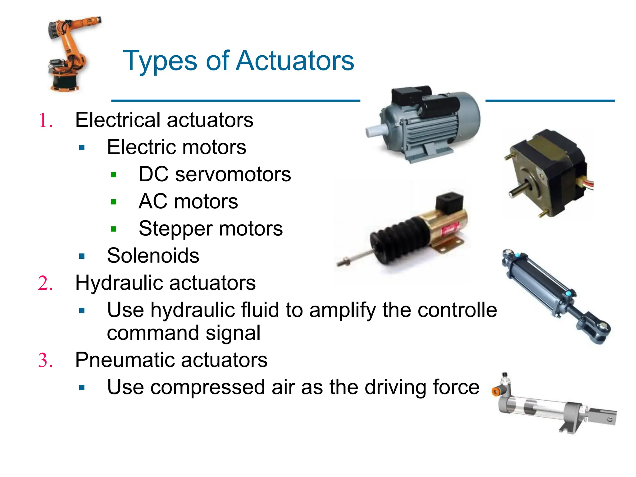
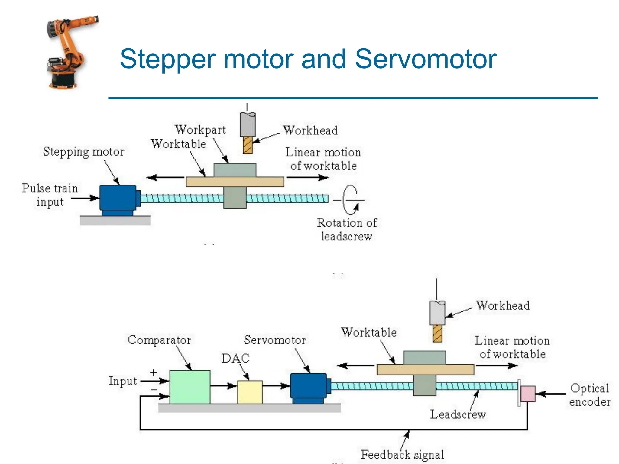
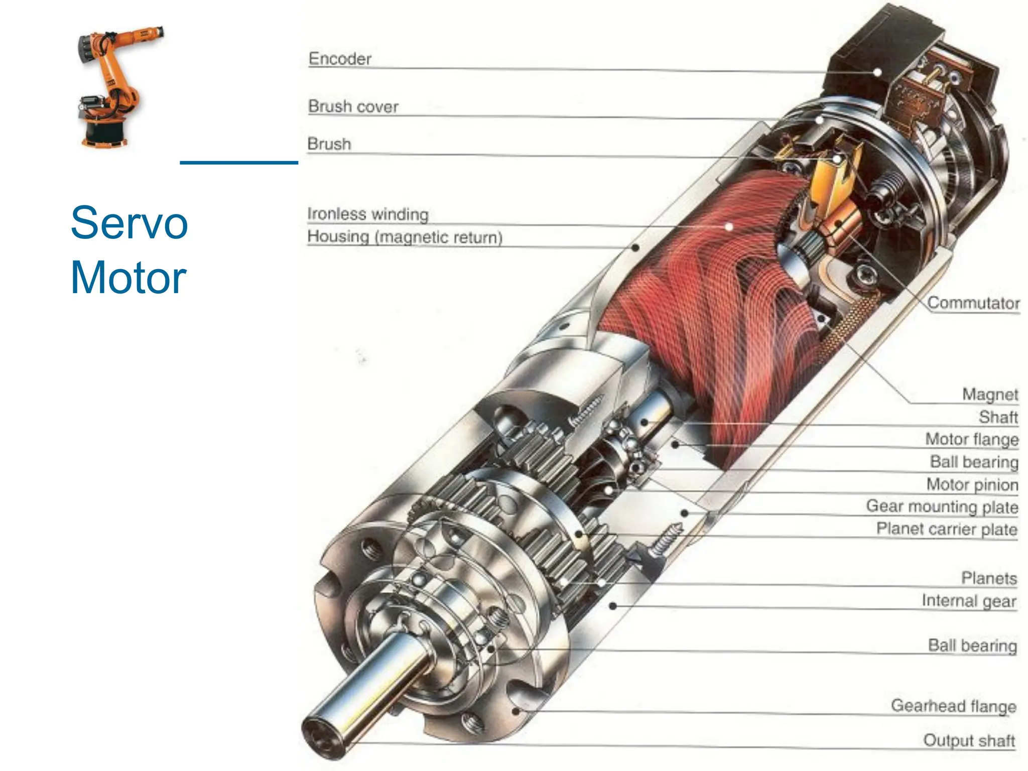
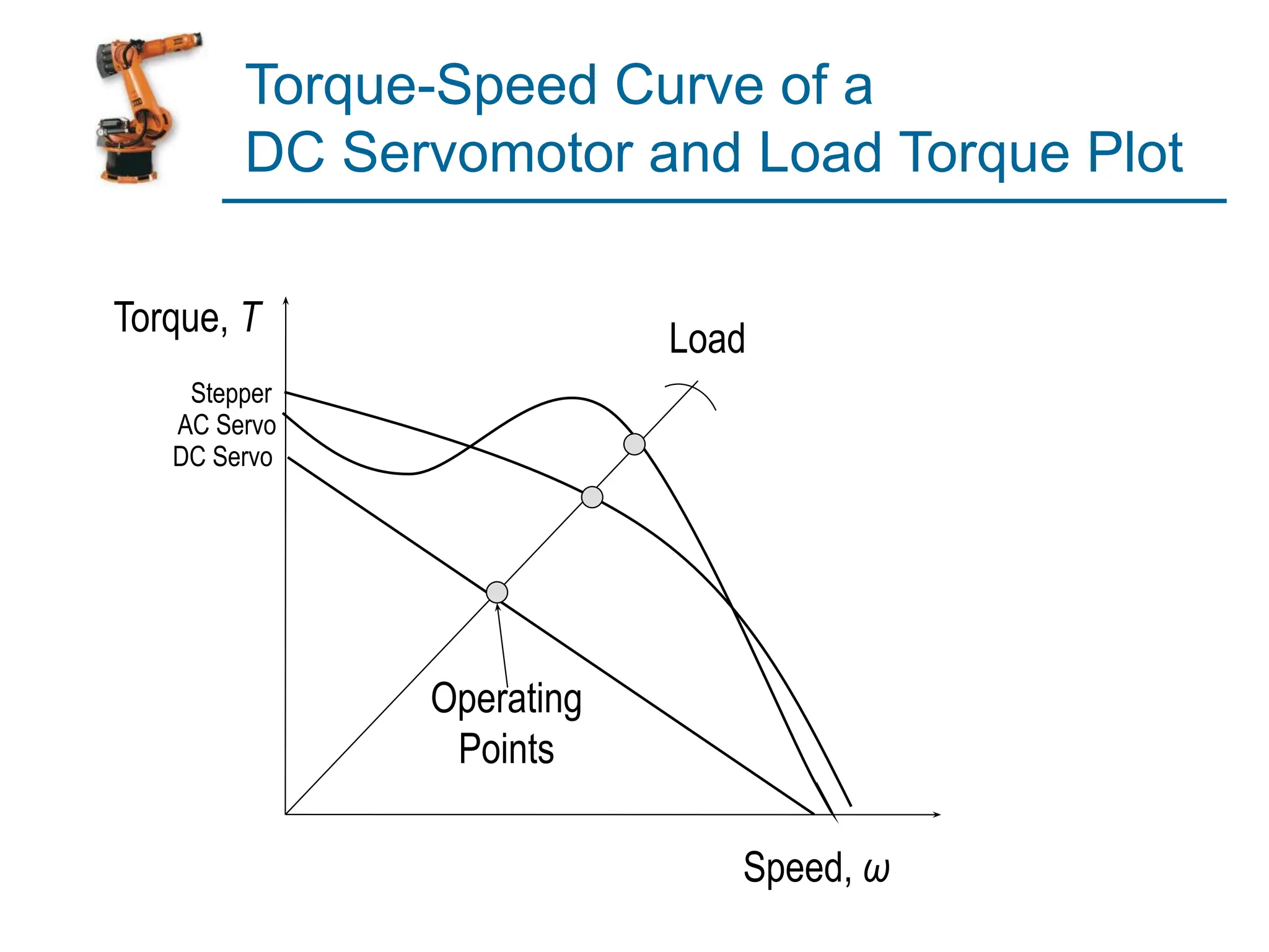
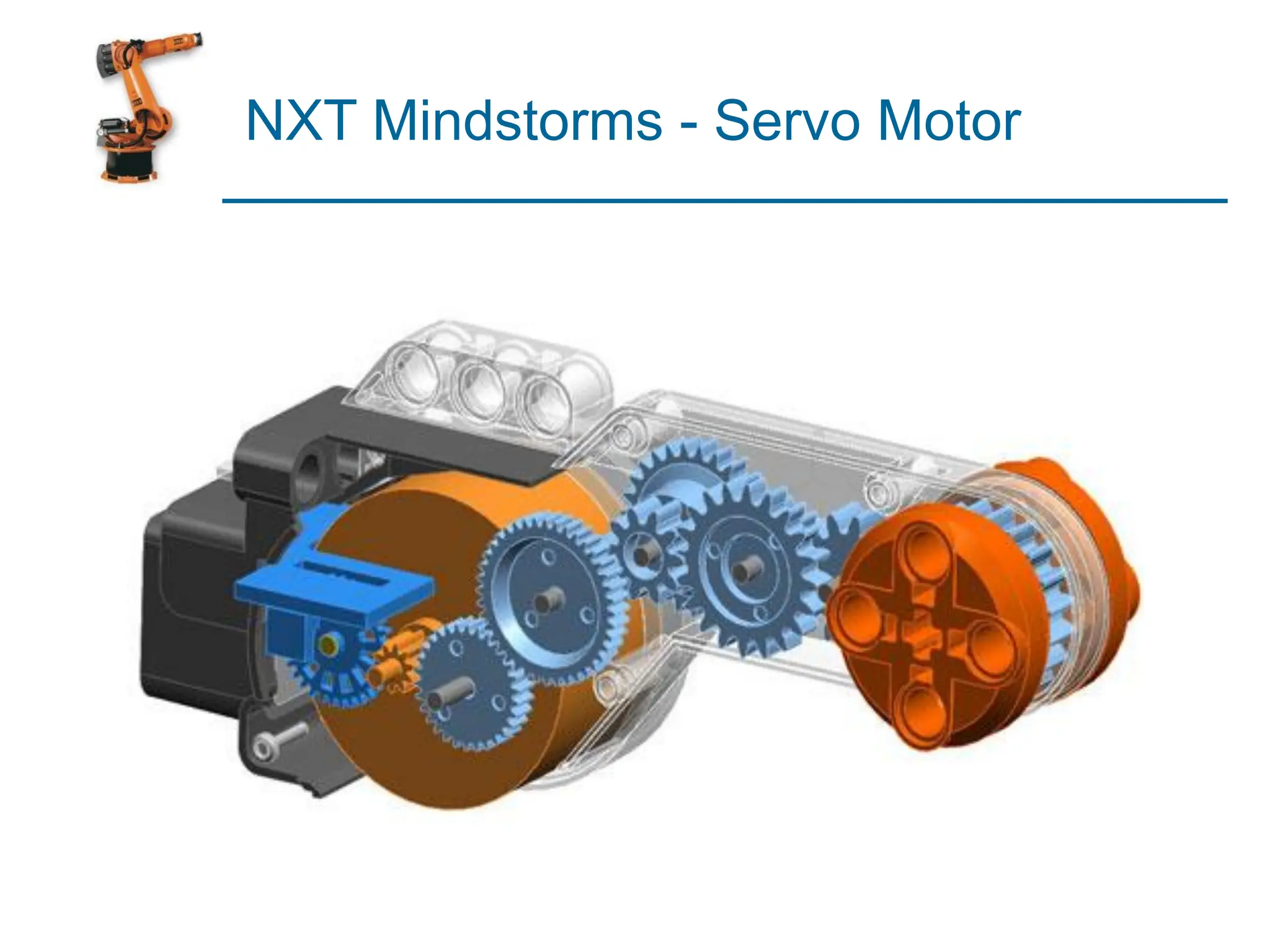
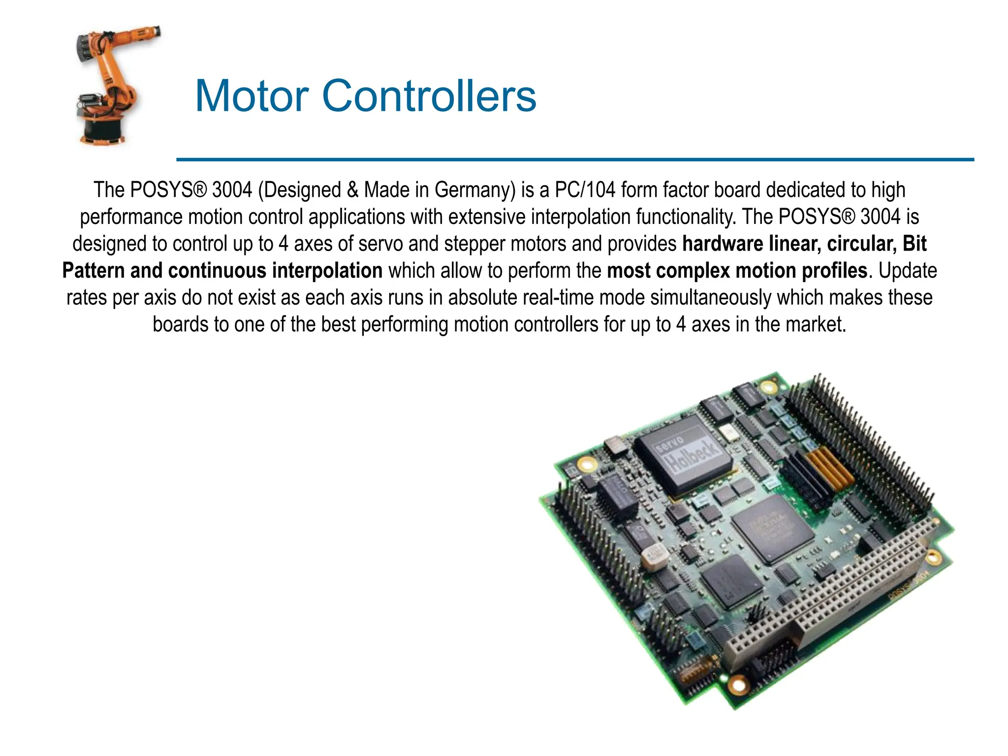
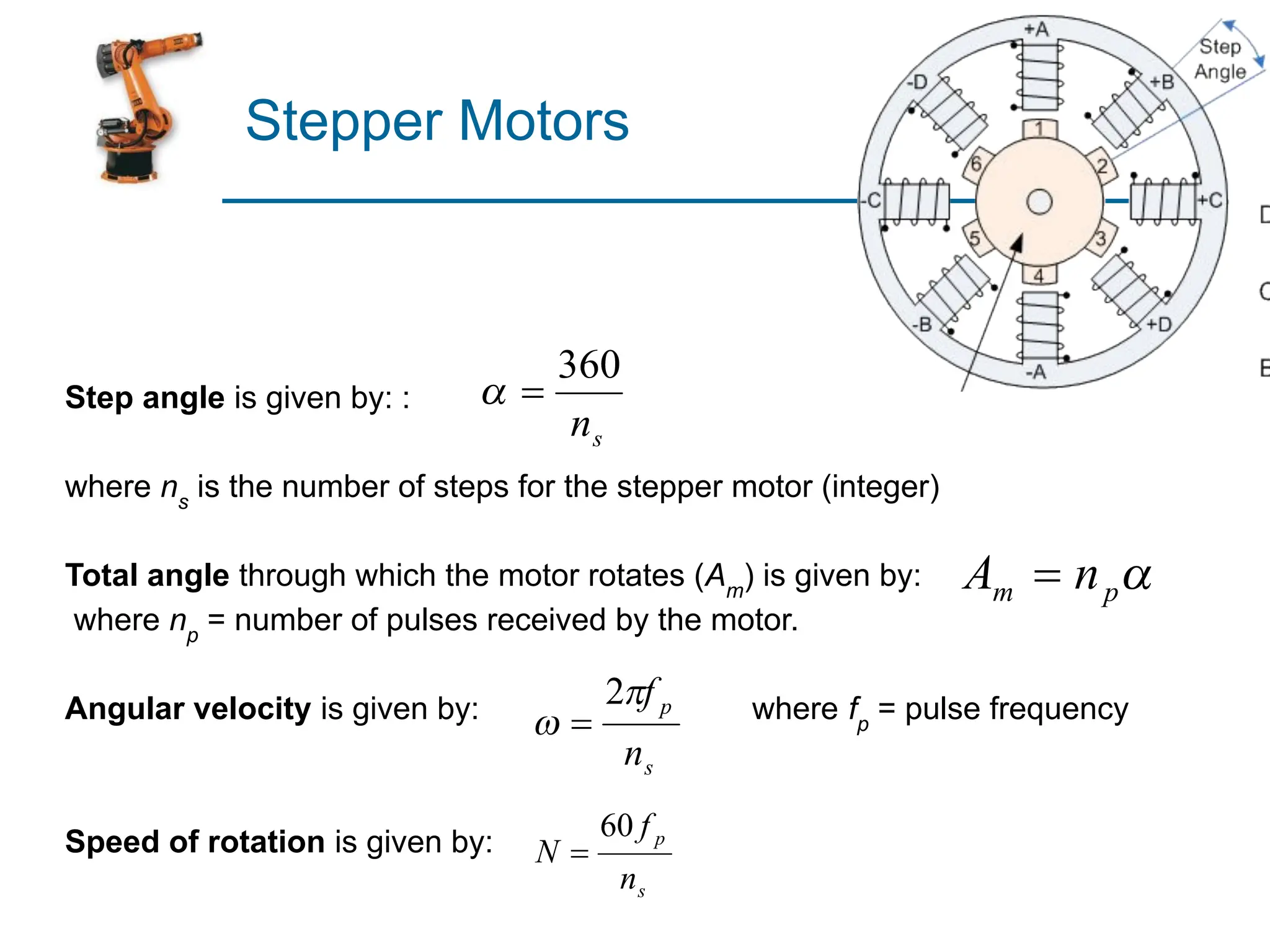
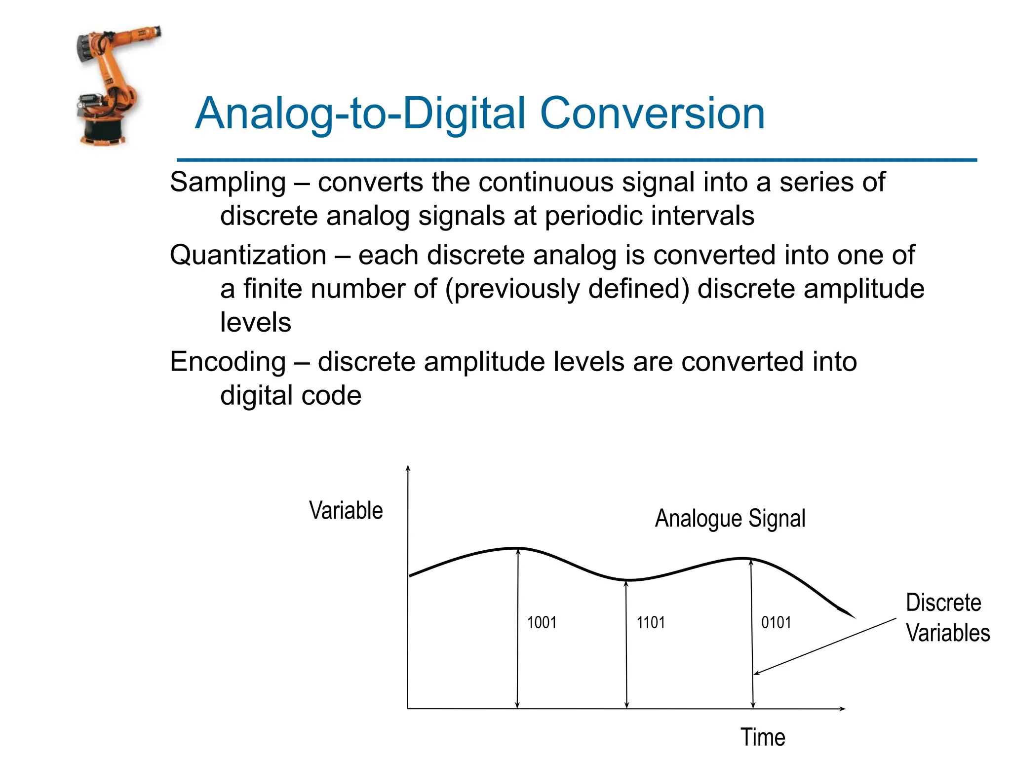
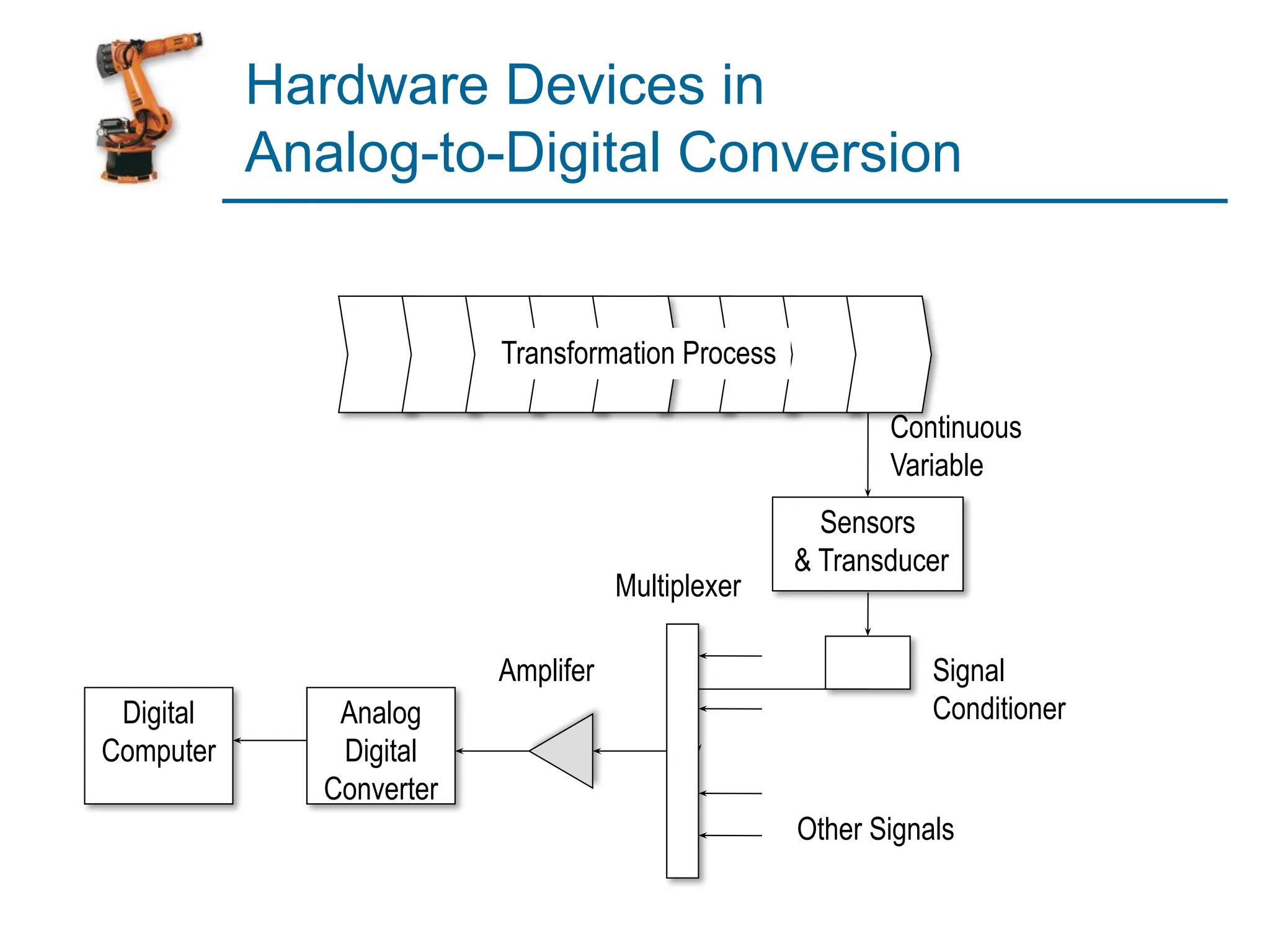
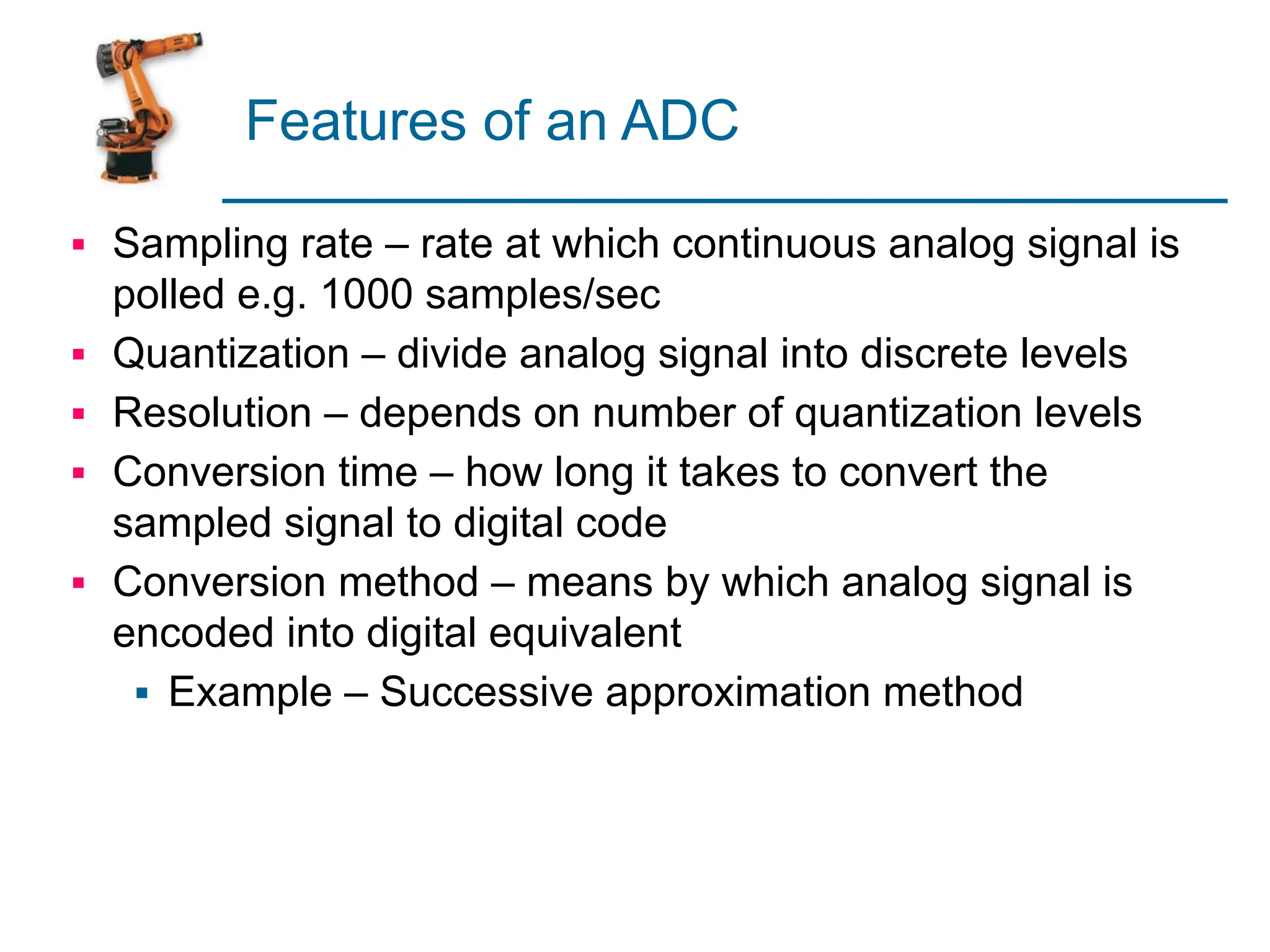
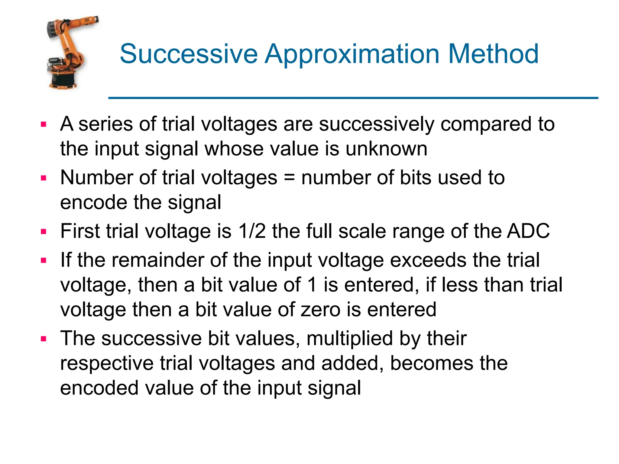
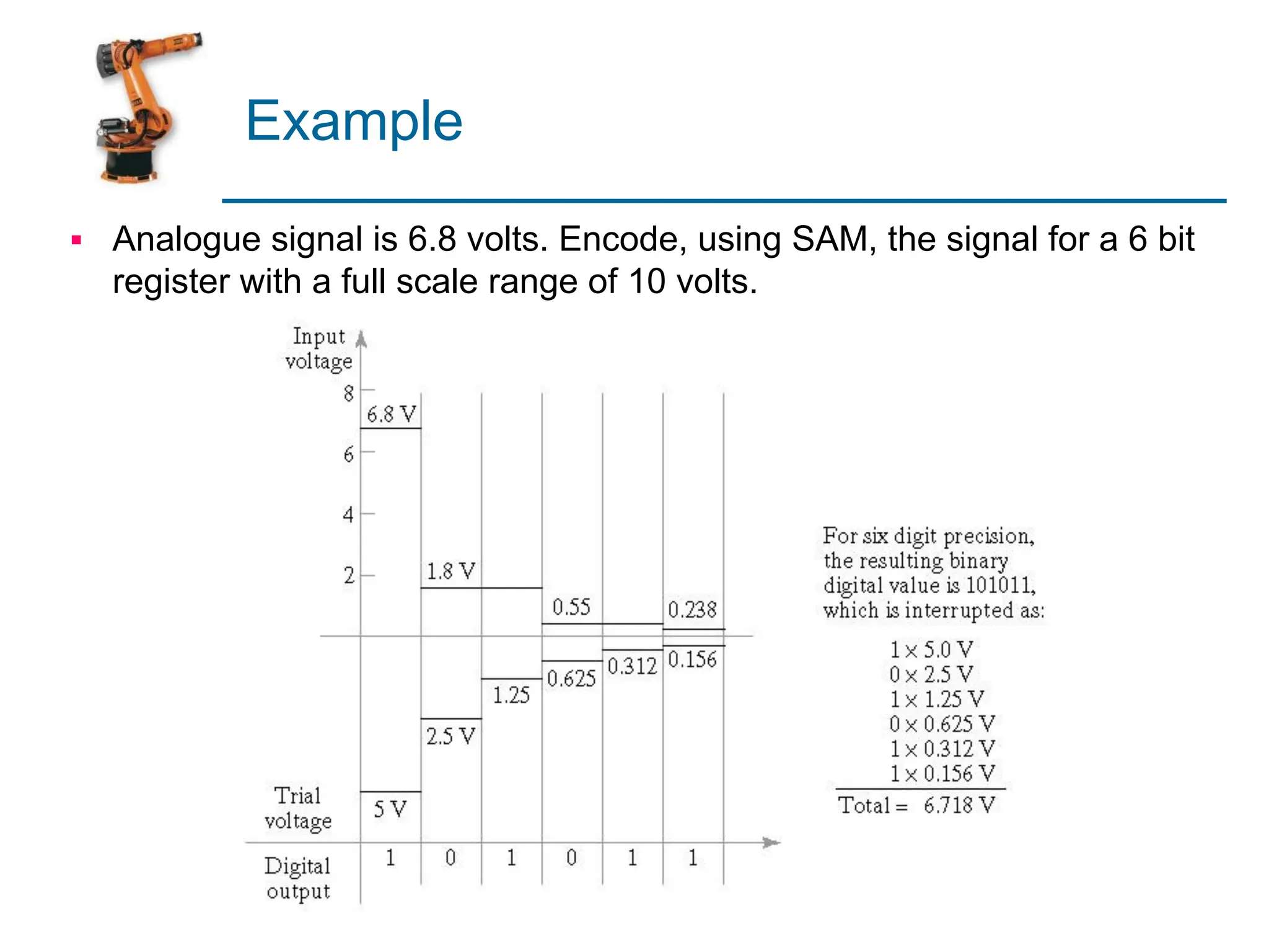
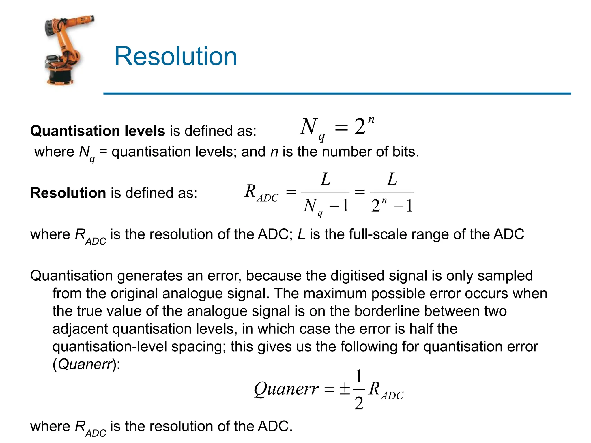
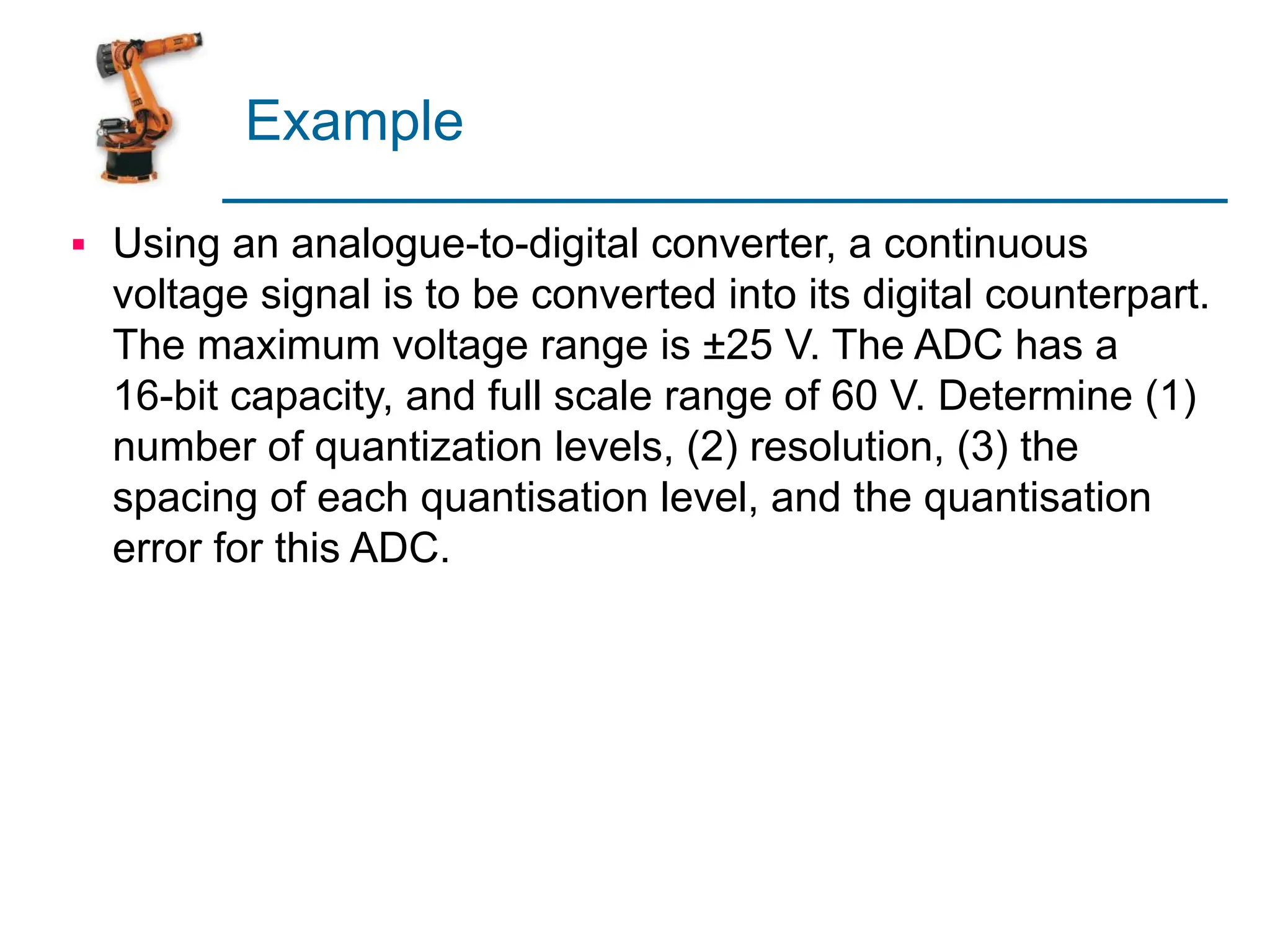
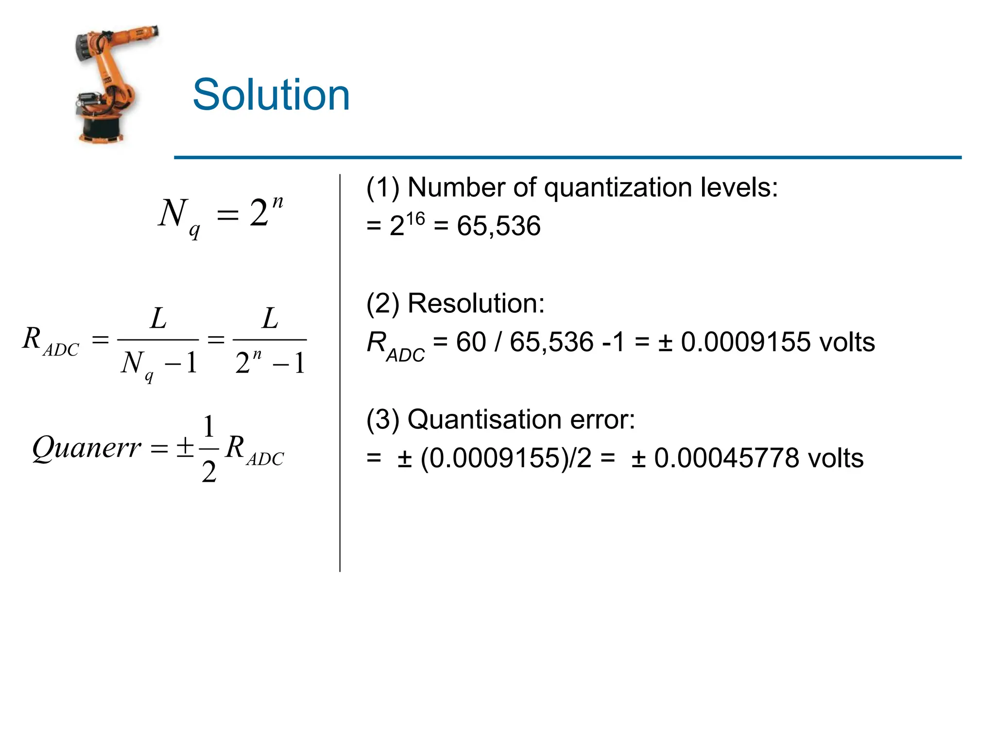
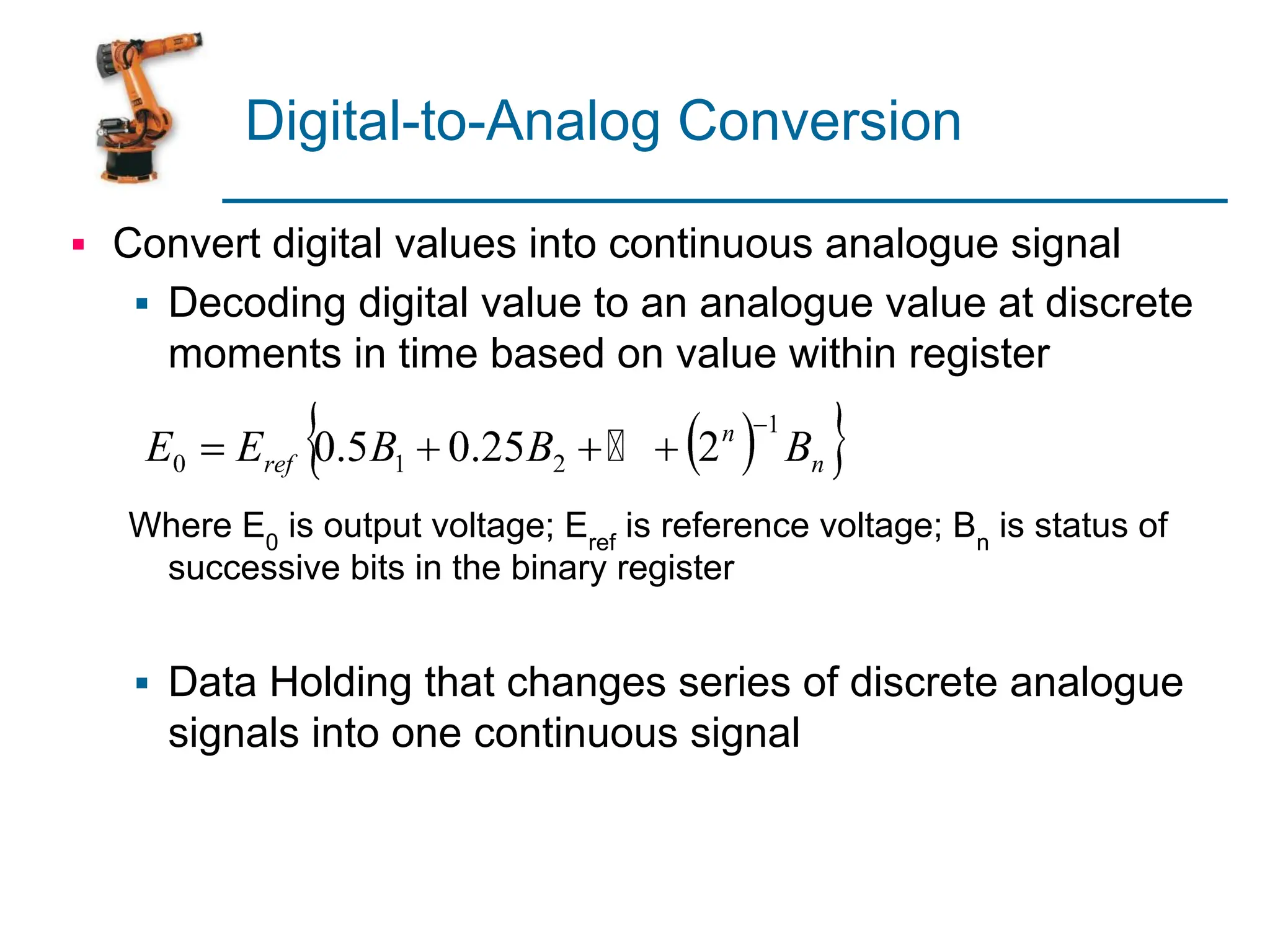
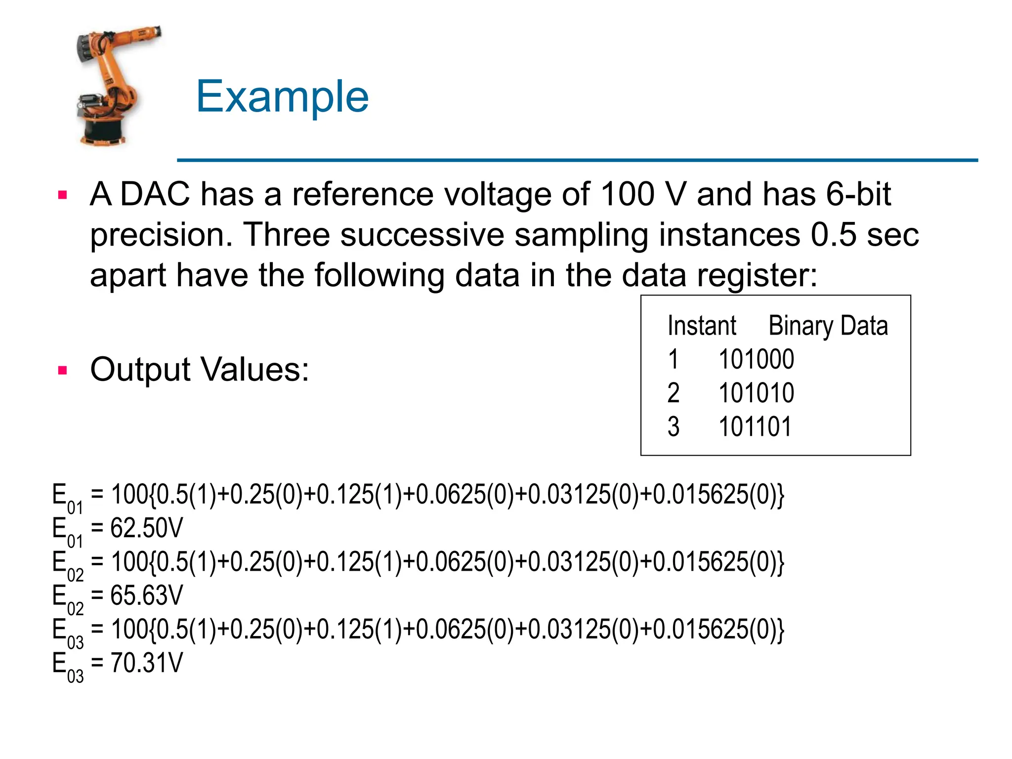
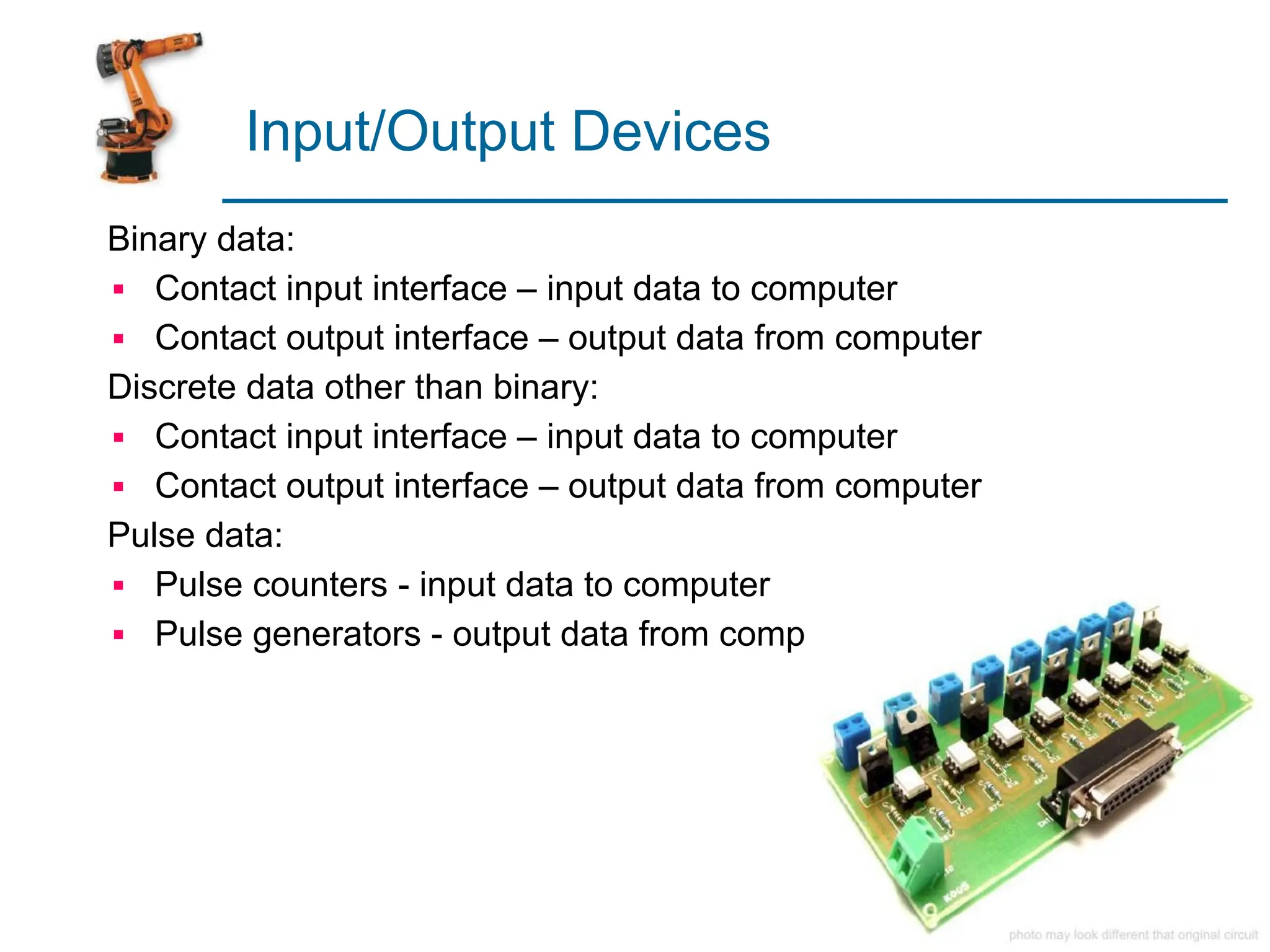
1. Sensors
2. Actuators
3. Analog-to-Digital Conversion
4. Digital-to-Analog Conversion
5. Input/Output Devices for Discrete Data
Computer-Process Interface
▪ To implement process control, the computer must
collect data from and transmit signals to the
production process
▪ Components required to implement the interface:
▪ Sensors to measure continuous and discrete
process variables
▪ Actuators to drive continuous and discrete process
parameters
▪ Devices for ADC and DAC
▪ I/O devices for discrete data
Computer Process Control System
Actuators
Computer
Controller
Transformation Process
Sensors
DAC ADC
Input Devices
Output Devices
Continuous and Discrete
Variables
Continuous and Discrete
Parameters
Sensors
Physical
Medium Sensing
Element
Conditionin
g
Target
Handling
Temperature Resistance Voltage Information
Transducers
Micro-sensors 10-6
m
Stimulus (s) Signal (S)
Transfer Function
where S = output signal; s = stimulus; and f(s) = functional relationship
For binary sensors: S = 1 if s > 0 and S = 0 if s < 0.
The ideal functional form for an analogue measuring device is a simple
proportional relationship, such as:
where C = output value at a stimulus value of zero
and m = constant of proportionality (sensitivity)
Example
▪ The output voltage of a particular thermocouple sensor is
registered to be 42.3 mV at temperature 105°C. It had
previously been set to emit a zero voltage at 0°C. Since an
output/input relationship exists between the two
temperatures, determine (1) the transfer function of the
thermocouple, and (2) the temperature corresponding to a
voltage output of 15.8 mV.
Solution
42.3 mV = 0 + m(105°C) = m(105°C)
or m = 0.4028571429
S = 0.4 (s)
15.8 mV = 0.4 (s)
15.8 / 0.4 = s
s = 39.22°C
Sensors
A sensor is a transducer that converts a physical
stimulus from one form into a more useful form to
measure the stimulus
▪ Two basic categories:
1. Analog
2. Discrete
▪ Binary
▪ Digital (e.g., pulse counter)
Ultrasonic
(distance)
Light
(light intensity)
Touch
Sound
(db pressure)
Other Sensors
▪ Temperature
▪ RFID
▪ Barcode
▪ Proximity
▪ Vision
▪ Gyroscope
▪ Compass
▪ Tilt/Acceleration
▪ Etc.
Actuators
Hardware devices that convert a controller command signal
into a change in a physical parameter
▪ The change is usually mechanical (e.g., position or
velocity)
▪ An actuator is also a transducer because it changes one
type of physical quantity into some alternative form
▪ An actuator is usually activated by a low-level command
signal, so an amplifier may be required to provide
sufficient power to drive the actuator
Actuators
Signal
Processing
& Amplification
Mechanism
Electric Hydraulic
Pneumatic
Final Actuation
Element
Actuator
Sensor
Logical
Signal
Types of Actuators
1. Electrical actuators
▪ Electric motors
▪ DC servomotors
▪ AC motors
▪ Stepper motors
▪ Solenoids
2. Hydraulic actuators
▪ Use hydraulic fluid to amplify the controller
command signal
3. Pneumatic actuators
▪ Use compressed air as the driving force
Stepper motor and Servomotor
Servo
Motor
Torque-Speed Curve of a
DC Servomotor and Load Torque Plot
Torque, T
Speed, ω
Load
Operating
Points
DC Servo
AC Servo
Stepper
NXT Mindstorms - Servo Motor
Motor Controllers
The POSYS® 3004 (Designed & Made in Germany) is a PC/104 form factor board dedicated to high
performance motion control applications with extensive interpolation functionality. The POSYS® 3004 is
designed to control up to 4 axes of servo and stepper motors and provides hardware linear, circular, Bit
Pattern and continuous interpolation which allow to perform the most complex motion profiles. Update
rates per axis do not exist as each axis runs in absolute real-time mode simultaneously which makes these
boards to one of the best performing motion controllers for up to 4 axes in the market.
Stepper Motors
Step angle is given by: :
where ns
is the number of steps for the stepper motor (integer)
Total angle through which the motor rotates (Am
) is given by:
where np
= number of pulses received by the motor.
Angular velocity is given by: where fp
= pulse frequency
Speed of rotation is given by:
Example
▪ A stepper motor has a step angle = 3.6°. (1) How many
pulses are required for the motor to rotate through ten
complete revolutions? (2) What pulse frequency is
required for the motor to rotate at a speed of 100 rev/min?
Solution
(1) 3.6° = 360 / ns
; 3.6° (ns
) = 360; ns
= 360 / 3.6 = 100 step
angles
(2) Ten complete revolutions: 10(360°) = 3600° = Am
Therefore np
= 3600 / 3.6 = 1000 pulses
Where N = 100 rev/min:
100 = 60 fp
/ 100
10,000 = 60 fp
fp
= 10,000 / 60 = 166.667 = 167 Hz
Analog-to-Digital Conversion
Sampling – converts the continuous signal into a series of
discrete analog signals at periodic intervals
Quantization – each discrete analog is converted into one of
a finite number of (previously defined) discrete amplitude
levels
Encoding – discrete amplitude levels are converted into
digital code
Variable
Time
Analogue Signal
1001 1101 0101
Discrete
Variables
Hardware Devices in
Analog-to-Digital Conversion
Analog
Digital
Converter
Transformation Process
Sensors
& Transducer
Other Signals
Continuous
Variable
Signal
Conditioner
Multiplexer
Digital
Computer
Amplifer
Features of an ADC
▪ Sampling rate – rate at which continuous analog signal is
polled e.g. 1000 samples/sec
▪ Quantization – divide analog signal into discrete levels
▪ Resolution – depends on number of quantization levels
▪ Conversion time – how long it takes to convert the
sampled signal to digital code
▪ Conversion method – means by which analog signal is
encoded into digital equivalent
▪ Example – Successive approximation method
Successive Approximation Method
▪ A series of trial voltages are successively compared to
the input signal whose value is unknown
▪ Number of trial voltages = number of bits used to
encode the signal
▪ First trial voltage is 1/2 the full scale range of the ADC
▪ If the remainder of the input voltage exceeds the trial
voltage, then a bit value of 1 is entered, if less than trial
voltage then a bit value of zero is entered
▪ The successive bit values, multiplied by their
respective trial voltages and added, becomes the
encoded value of the input signal
Example
▪ Analogue signal is 6.8 volts. Encode, using SAM, the signal for a 6 bit
register with a full scale range of 10 volts.
Resolution
Quantisation levels is defined as:
where Nq
= quantisation levels; and n is the number of bits.
Resolution is defined as:
where RADC
is the resolution of the ADC; L is the full-scale range of the ADC
Quantisation generates an error, because the digitised signal is only sampled
from the original analogue signal. The maximum possible error occurs when
the true value of the analogue signal is on the borderline between two
adjacent quantisation levels, in which case the error is half the
quantisation-level spacing; this gives us the following for quantisation error
(Quanerr):
where RADC
is the resolution of the ADC.
Example
▪ Using an analogue-to-digital converter, a continuous
voltage signal is to be converted into its digital counterpart.
The maximum voltage range is ±25 V. The ADC has a
16-bit capacity, and full scale range of 60 V. Determine (1)
number of quantization levels, (2) resolution, (3) the
spacing of each quantisation level, and the quantisation
error for this ADC.
Solution
(1) Number of quantization levels:
= 216
= 65,536
(2) Resolution:
RADC
= 60 / 65,536 -1 = ± 0.0009155 volts
(3) Quantisation error:
= ± (0.0009155)/2 = ± 0.00045778 volts
Digital-to-Analog Conversion
▪ Convert digital values into continuous analogue signal
▪ Decoding digital value to an analogue value at discrete
moments in time based on value within register
Where E0
is output voltage; Eref
is reference voltage; Bn
is status of
successive bits in the binary register
▪ Data Holding that changes series of discrete analogue
signals into one continuous signal
Example
▪ A DAC has a reference voltage of 100 V and has 6-bit
precision. Three successive sampling instances 0.5 sec
apart have the following data in the data register:
▪ Output Values:
Instant Binary Data
1 101000
2 101010
3 101101
E01
= 100{0.5(1)+0.25(0)+0.125(1)+0.0625(0)+0.03125(0)+0.015625(0)}
E01
= 62.50V
E02
= 100{0.5(1)+0.25(0)+0.125(1)+0.0625(0)+0.03125(0)+0.015625(0)}
E02
= 65.63V
E03
= 100{0.5(1)+0.25(0)+0.125(1)+0.0625(0)+0.03125(0)+0.015625(0)}
E03
= 70.31V
Input/Output Devices
Binary data:
▪ Contact input interface – input data to computer
▪ Contact output interface – output data from computer
Discrete data other than binary:
▪ Contact input interface – input data to computer
▪ Contact output interface – output data from computer
Pulse data:
▪ Pulse counters - input data to computer
▪ Pulse generators - output data from computer

Types of Actuators and Sensors in Robotics

  • 1.
    1. Sensors 2. Actuators 3.Analog-to-Digital Conversion 4. Digital-to-Analog Conversion 5. Input/Output Devices for Discrete Data
  • 2.
    Computer-Process Interface ▪ Toimplement process control, the computer must collect data from and transmit signals to the production process ▪ Components required to implement the interface: ▪ Sensors to measure continuous and discrete process variables ▪ Actuators to drive continuous and discrete process parameters ▪ Devices for ADC and DAC ▪ I/O devices for discrete data
  • 3.
    Computer Process ControlSystem Actuators Computer Controller Transformation Process Sensors DAC ADC Input Devices Output Devices Continuous and Discrete Variables Continuous and Discrete Parameters
  • 4.
    Sensors Physical Medium Sensing Element Conditionin g Target Handling Temperature ResistanceVoltage Information Transducers Micro-sensors 10-6 m Stimulus (s) Signal (S)
  • 5.
    Transfer Function where S= output signal; s = stimulus; and f(s) = functional relationship For binary sensors: S = 1 if s > 0 and S = 0 if s < 0. The ideal functional form for an analogue measuring device is a simple proportional relationship, such as: where C = output value at a stimulus value of zero and m = constant of proportionality (sensitivity)
  • 6.
    Example ▪ The outputvoltage of a particular thermocouple sensor is registered to be 42.3 mV at temperature 105°C. It had previously been set to emit a zero voltage at 0°C. Since an output/input relationship exists between the two temperatures, determine (1) the transfer function of the thermocouple, and (2) the temperature corresponding to a voltage output of 15.8 mV.
  • 7.
    Solution 42.3 mV =0 + m(105°C) = m(105°C) or m = 0.4028571429 S = 0.4 (s) 15.8 mV = 0.4 (s) 15.8 / 0.4 = s s = 39.22°C
  • 8.
    Sensors A sensor isa transducer that converts a physical stimulus from one form into a more useful form to measure the stimulus ▪ Two basic categories: 1. Analog 2. Discrete ▪ Binary ▪ Digital (e.g., pulse counter) Ultrasonic (distance) Light (light intensity) Touch Sound (db pressure)
  • 9.
    Other Sensors ▪ Temperature ▪RFID ▪ Barcode ▪ Proximity ▪ Vision ▪ Gyroscope ▪ Compass ▪ Tilt/Acceleration ▪ Etc.
  • 10.
    Actuators Hardware devices thatconvert a controller command signal into a change in a physical parameter ▪ The change is usually mechanical (e.g., position or velocity) ▪ An actuator is also a transducer because it changes one type of physical quantity into some alternative form ▪ An actuator is usually activated by a low-level command signal, so an amplifier may be required to provide sufficient power to drive the actuator
  • 11.
  • 12.
    Types of Actuators 1.Electrical actuators ▪ Electric motors ▪ DC servomotors ▪ AC motors ▪ Stepper motors ▪ Solenoids 2. Hydraulic actuators ▪ Use hydraulic fluid to amplify the controller command signal 3. Pneumatic actuators ▪ Use compressed air as the driving force
  • 13.
  • 14.
  • 15.
    Torque-Speed Curve ofa DC Servomotor and Load Torque Plot Torque, T Speed, ω Load Operating Points DC Servo AC Servo Stepper
  • 16.
    NXT Mindstorms -Servo Motor
  • 17.
    Motor Controllers The POSYS®3004 (Designed & Made in Germany) is a PC/104 form factor board dedicated to high performance motion control applications with extensive interpolation functionality. The POSYS® 3004 is designed to control up to 4 axes of servo and stepper motors and provides hardware linear, circular, Bit Pattern and continuous interpolation which allow to perform the most complex motion profiles. Update rates per axis do not exist as each axis runs in absolute real-time mode simultaneously which makes these boards to one of the best performing motion controllers for up to 4 axes in the market.
  • 18.
    Stepper Motors Step angleis given by: : where ns is the number of steps for the stepper motor (integer) Total angle through which the motor rotates (Am ) is given by: where np = number of pulses received by the motor. Angular velocity is given by: where fp = pulse frequency Speed of rotation is given by:
  • 19.
    Example ▪ A steppermotor has a step angle = 3.6°. (1) How many pulses are required for the motor to rotate through ten complete revolutions? (2) What pulse frequency is required for the motor to rotate at a speed of 100 rev/min?
  • 20.
    Solution (1) 3.6° =360 / ns ; 3.6° (ns ) = 360; ns = 360 / 3.6 = 100 step angles (2) Ten complete revolutions: 10(360°) = 3600° = Am Therefore np = 3600 / 3.6 = 1000 pulses Where N = 100 rev/min: 100 = 60 fp / 100 10,000 = 60 fp fp = 10,000 / 60 = 166.667 = 167 Hz
  • 21.
    Analog-to-Digital Conversion Sampling –converts the continuous signal into a series of discrete analog signals at periodic intervals Quantization – each discrete analog is converted into one of a finite number of (previously defined) discrete amplitude levels Encoding – discrete amplitude levels are converted into digital code Variable Time Analogue Signal 1001 1101 0101 Discrete Variables
  • 22.
    Hardware Devices in Analog-to-DigitalConversion Analog Digital Converter Transformation Process Sensors & Transducer Other Signals Continuous Variable Signal Conditioner Multiplexer Digital Computer Amplifer
  • 23.
    Features of anADC ▪ Sampling rate – rate at which continuous analog signal is polled e.g. 1000 samples/sec ▪ Quantization – divide analog signal into discrete levels ▪ Resolution – depends on number of quantization levels ▪ Conversion time – how long it takes to convert the sampled signal to digital code ▪ Conversion method – means by which analog signal is encoded into digital equivalent ▪ Example – Successive approximation method
  • 24.
    Successive Approximation Method ▪A series of trial voltages are successively compared to the input signal whose value is unknown ▪ Number of trial voltages = number of bits used to encode the signal ▪ First trial voltage is 1/2 the full scale range of the ADC ▪ If the remainder of the input voltage exceeds the trial voltage, then a bit value of 1 is entered, if less than trial voltage then a bit value of zero is entered ▪ The successive bit values, multiplied by their respective trial voltages and added, becomes the encoded value of the input signal
  • 25.
    Example ▪ Analogue signalis 6.8 volts. Encode, using SAM, the signal for a 6 bit register with a full scale range of 10 volts.
  • 26.
    Resolution Quantisation levels isdefined as: where Nq = quantisation levels; and n is the number of bits. Resolution is defined as: where RADC is the resolution of the ADC; L is the full-scale range of the ADC Quantisation generates an error, because the digitised signal is only sampled from the original analogue signal. The maximum possible error occurs when the true value of the analogue signal is on the borderline between two adjacent quantisation levels, in which case the error is half the quantisation-level spacing; this gives us the following for quantisation error (Quanerr): where RADC is the resolution of the ADC.
  • 27.
    Example ▪ Using ananalogue-to-digital converter, a continuous voltage signal is to be converted into its digital counterpart. The maximum voltage range is ±25 V. The ADC has a 16-bit capacity, and full scale range of 60 V. Determine (1) number of quantization levels, (2) resolution, (3) the spacing of each quantisation level, and the quantisation error for this ADC.
  • 28.
    Solution (1) Number ofquantization levels: = 216 = 65,536 (2) Resolution: RADC = 60 / 65,536 -1 = ± 0.0009155 volts (3) Quantisation error: = ± (0.0009155)/2 = ± 0.00045778 volts
  • 29.
    Digital-to-Analog Conversion ▪ Convertdigital values into continuous analogue signal ▪ Decoding digital value to an analogue value at discrete moments in time based on value within register Where E0 is output voltage; Eref is reference voltage; Bn is status of successive bits in the binary register ▪ Data Holding that changes series of discrete analogue signals into one continuous signal
  • 30.
    Example ▪ A DAChas a reference voltage of 100 V and has 6-bit precision. Three successive sampling instances 0.5 sec apart have the following data in the data register: ▪ Output Values: Instant Binary Data 1 101000 2 101010 3 101101 E01 = 100{0.5(1)+0.25(0)+0.125(1)+0.0625(0)+0.03125(0)+0.015625(0)} E01 = 62.50V E02 = 100{0.5(1)+0.25(0)+0.125(1)+0.0625(0)+0.03125(0)+0.015625(0)} E02 = 65.63V E03 = 100{0.5(1)+0.25(0)+0.125(1)+0.0625(0)+0.03125(0)+0.015625(0)} E03 = 70.31V
  • 31.
    Input/Output Devices Binary data: ▪Contact input interface – input data to computer ▪ Contact output interface – output data from computer Discrete data other than binary: ▪ Contact input interface – input data to computer ▪ Contact output interface – output data from computer Pulse data: ▪ Pulse counters - input data to computer ▪ Pulse generators - output data from computer