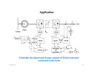
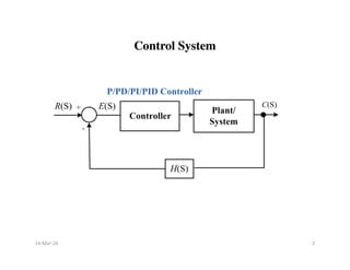
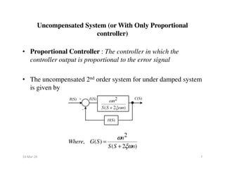
This document discusses the design, implementation, and applications of controllers. It describes how controllers can be designed in the time domain or frequency domain. The main types of controllers discussed are proportional (P), proportional-derivative (PD), proportional-integral (PI), and proportional-integral-derivative (PID) controllers. It explains how each type of controller affects the transient response and steady-state response by improving damping ratio, reducing settling time and overshoot, and reducing steady-state error. The effects of adding poles and zeros to open-loop and closed-loop transfer functions are also covered. Finally, an example application of using a PID controller for speed and torque control of a wind generator connected to the power grid is mentioned.
![Derivative Output compensation (Derivative Output
Controller) Output Rate Controller
Derivative Output compensation (Derivative Output
Controller) Output Rate Controller
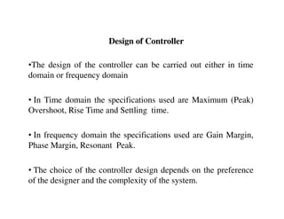
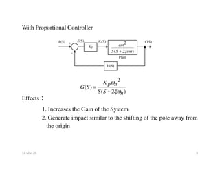
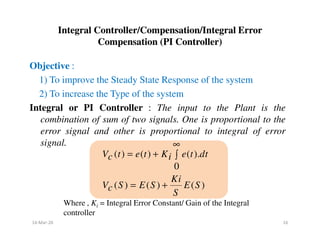
Objective :
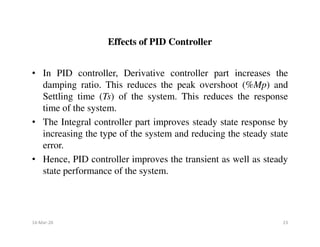
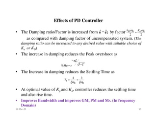
1) To improve the Transient Response by improving ( )
3) To reduce the Peak overshoot (%Mp) and Settling time (Ts)
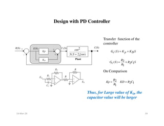
Derivative Controller/PD Controller : The derivative of the
output signal is compared with the error signal and the
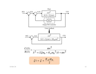
ξ
output signal is compared with the error signal and the
resultant is given as input to the plant.
[ ( )]
( ) ( )
( ) ( ) ( )
d C t
V t e t K
c o
dt
V S E S K S C S
c o
= −
= −
Where , Ko = Derivative output Constant / Tachometer
feedback constant
14-Mar-20 11](https://image.slidesharecdn.com/controllers-240116235519-093e0293/85/controllers-ITS-TYPES-AND-CLASSIFICATION-BASED-ON-APPLICATION-11-320.jpg)
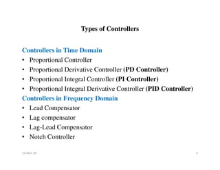
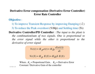
![Effect of Addition of Zero to the Close loop Transfer Function
(Unity Feedback System)
Effect of Addition of Zero to the Close loop Transfer Function
(Unity Feedback System)
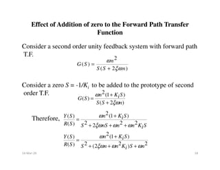
Consider a closed loop T.F. of second order uncompensated system
Consider a zero S = -1/KD to be added to the prototype of second
order T.F.
2
2
( )
2 2
( ) 2
Y S n
R S S nS n
ω
ξω ω
=
+ +
2(1 )
( )
2 2
( ) 2
2
2
( )
2 2 2 2
( ) 2 2
[ ( )]
( ) 1
( )
1
( )
n K S
Y S D
R S S nS n
K S n
Y S n D
R S S nS n S nS n
d Y t
Y S
Y t KD
R S dt
ω
ξω ω
ω
ω
ξω ω ξω ω
+
=
+ +
= +
+ + + +
= +
For ωn = 1, ξ = 0.5 and KD = 0, 1, 3, 6, 10
14-Mar-20 13](https://image.slidesharecdn.com/controllers-240116235519-093e0293/85/controllers-ITS-TYPES-AND-CLASSIFICATION-BASED-ON-APPLICATION-13-320.jpg)
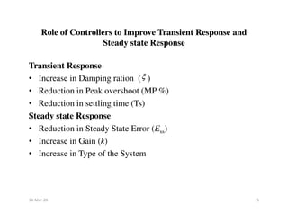
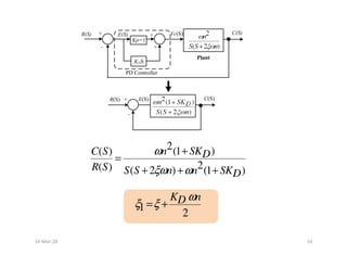
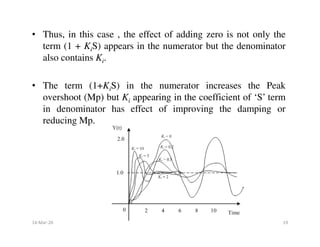
![• As KD increases, zero will move closer to the origin, thus decreasing the
rise time and increasing the peak overshoot (Mp)
• Thus Y1(t) increases by after adding a zero to the close loop T.F..
Thus it increases the Mp and decreases the rise time.
• As KD approaches to infinity, Mp also approaches to infinity and yet the
system is stable as long as peak overshoot (Mp) is finite and damping is
positive.
[ 1( )]
d Y t
KD
dt
14-Mar-20 14](https://image.slidesharecdn.com/controllers-240116235519-093e0293/85/controllers-ITS-TYPES-AND-CLASSIFICATION-BASED-ON-APPLICATION-14-320.jpg)
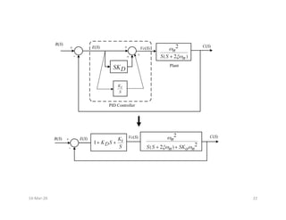
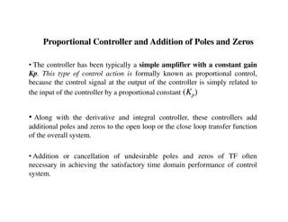
![Proportional Integral Derivative Controller
(PID Controller)
Proportional Integral Derivative Controller
(PID Controller)
Objective :
1) To improve the Transient and Steady State Response of the
system
PID Controller : In PID Controller, input to the plant is a
combination /sum of three signals. First is the proportional to
the error signal, second is proportional to derivative of error
the error signal, second is proportional to derivative of error
signal and the third is proportional to the integral of error
signal.
[ ( )]
( ) ( ) ( ).
0
( ) ( ) ( ) ( )
d e t
V t e t K K e t dt
c D i
dt
Ki
Vc S E S K S E S E S
D
S
∞
= + + ∫
= + +
Where , KD and Ki = Gains of Derivative and Integral
Controllers, respectively.
14-Mar-20 21](https://image.slidesharecdn.com/controllers-240116235519-093e0293/85/controllers-ITS-TYPES-AND-CLASSIFICATION-BASED-ON-APPLICATION-21-320.jpg)