The document describes a two tank heating process and provides information about the tank properties. It then asks several questions:
1) Develop block diagrams relating outlet temperatures to inlet temperatures and heat flow rates. Expressions for the Laplace transforms of the outlet temperatures T1(s) and T2(s) are obtained.
2) Determine the expression for T2'(s) and use it to find T2(2) and T2(∞).
3) For a system with heat transfer between two nested tanks, an expression is obtained for the Laplace transform of the inner tank temperature T1(s). This is inverted to find T1(0), T1(5), T1(10
In this document
Powered by AI
Analysis of a two tank heating system; calculates outlet temperature based on heat flow and input temps.
Dynamic response modeling of temperature deviations in a two-tank heating system after step changes.
Modeling heat transfer dynamics between two nested tanks, calculating temperature over time and Laplace transforms.
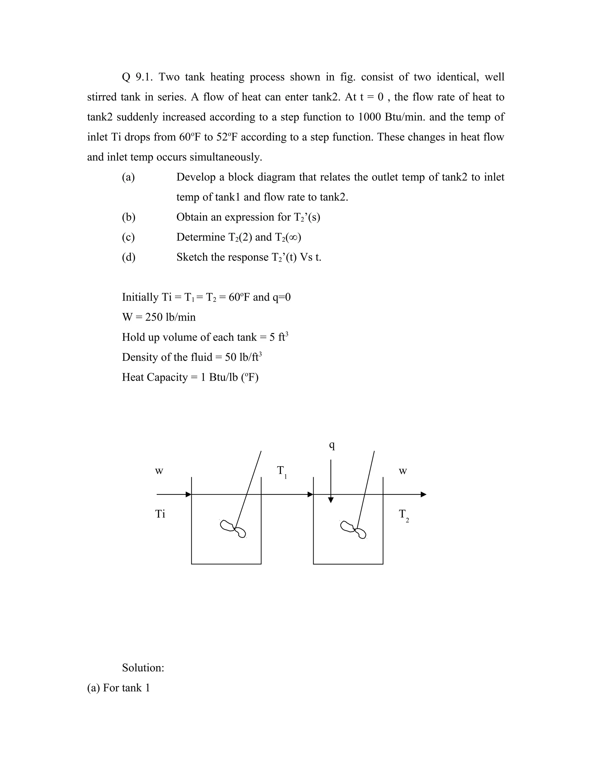
Q 9.1. Twotank heating process shown in fig. consist of two identical, well
stirred tank in series. A flow of heat can enter tank2. At t = 0 , the flow rate of heat to
tank2 suddenly increased according to a step function to 1000 Btu/min. and the temp of
inlet Ti drops from 60oF to 52oF according to a step function. These changes in heat flow
and inlet temp occurs simultaneously.
(a) Develop a block diagram that relates the outlet temp of tank2 to inlet
temp of tank1 and flow rate to tank2.
(b) Obtain an expression for T2’(s)
(c) Determine T2(2) and T2(∞)
(d) Sketch the response T2’(t) Vs t.
Initially Ti = T1 = T2 = 60oF and q=0
W = 250 lb/min
Hold up volume of each tank = 5 ft3
Density of the fluid = 50 lb/ft3
Heat Capacity = 1 Btu/lb (oF)
q
w T1 w
Ti T2
Solution:
(a) For tank 1
2.
Input – output= accumulation
dT1
WC(Ti – To) - WC(T1 – To) = ρ C V -------------------------- (1)
dt
At steady state
WC(Tis – To) - WC(T1s – To) = 0 ------------------------------------(2)
(1) – (2) gives
dT '1
WC(Ti – Tis) - WC(T1 – T1s) = ρ C V
dt
’ ’ dT '1
WTi - WT1 = ρ V
dt
Taking Laplace transform
WTi(s) = WT1(s) + ρ V s T1(s)
T1 ( s ) 1
= , where τ = ρ V / W.
Ti ( s ) 1 +τs
From tank 2
dT2
q + WC(T1 – To) - WC(T2 – To) = ρ C V -------------------------- (3)
dt
At steady state
qs + WC(T1s – To) - WC(T2s – To) = 0 ------------------------------------(4)
(3) – (4) gives
dT ' 2
Q ‘ + WC(T1 – T1s) - WC(T2 – T2s) = ρ C V
dt
‘ ’ ’ dT ' 2
Q + WCT1 - WCT2 = ρ C V
dt
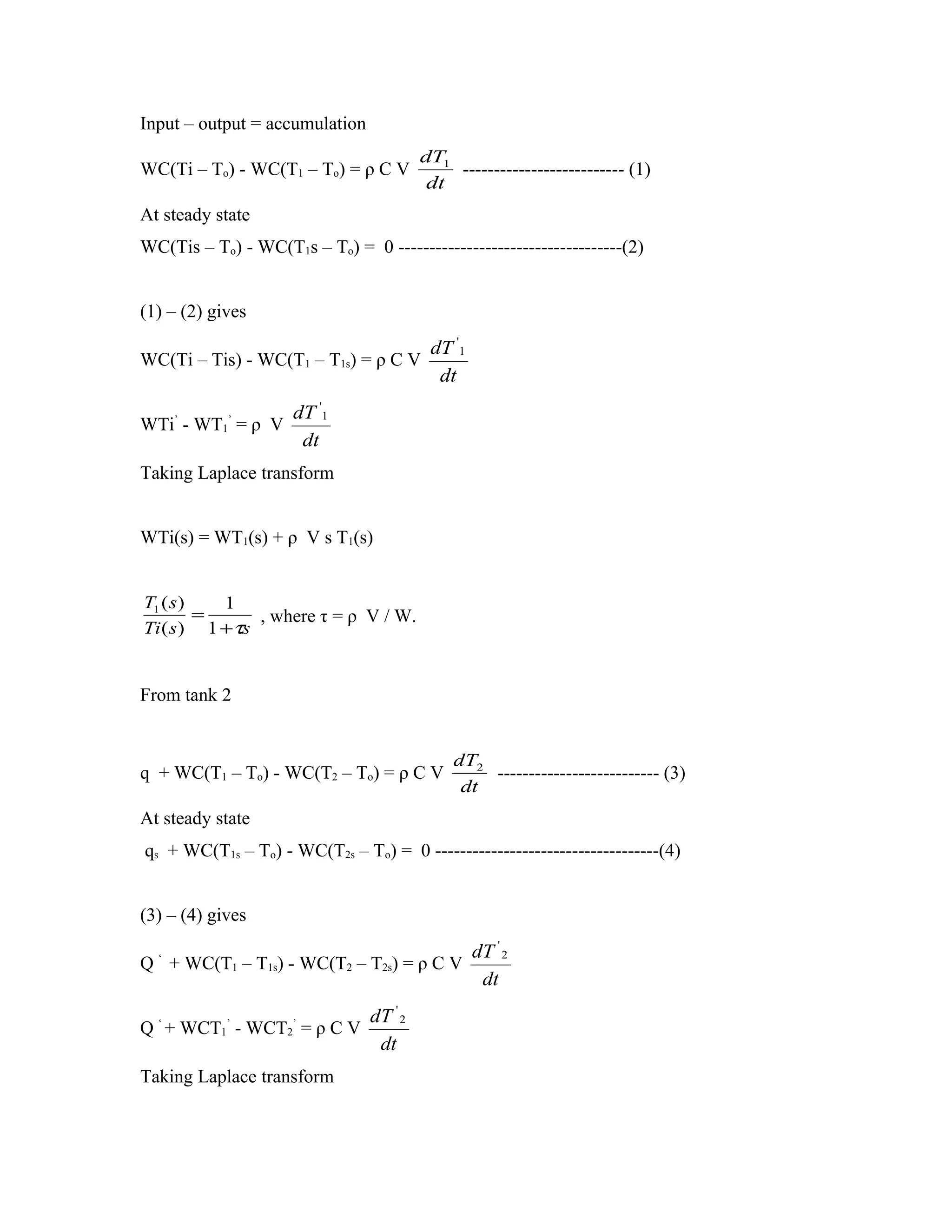
Taking Laplace transform
3.
Q (s) +WC(T1(s) - T2(s)) = ρ C V s T2(s)
1 Q( s)
T2 ( s ) = WC + T1 ( s ) , where τ = ρ V / W.
1 + τs
(b) τ = 50*5/250 = 1 min
WC = 250*1 = 250
Ti(s) = -8/s and Q(s) = 1000/s
Now by using above two equations we relate T2 and Ti as below and after taking laplace
transform we will get T2(t)
1 Q( s) 1
T2 ( s ) = + Ti ( s )
1 + τs 250 (1 + τs ) 2
4 8
T2 ( s ) = −
(1 + s ) (1 + s ) 2
1 1 1 1 1
s (1 + s ) − 8 s − s + 1 −
T2 ( s ) = 4 −
(1 + s ) 2
T2 (t ) = (4 + 8t )e −t − 4
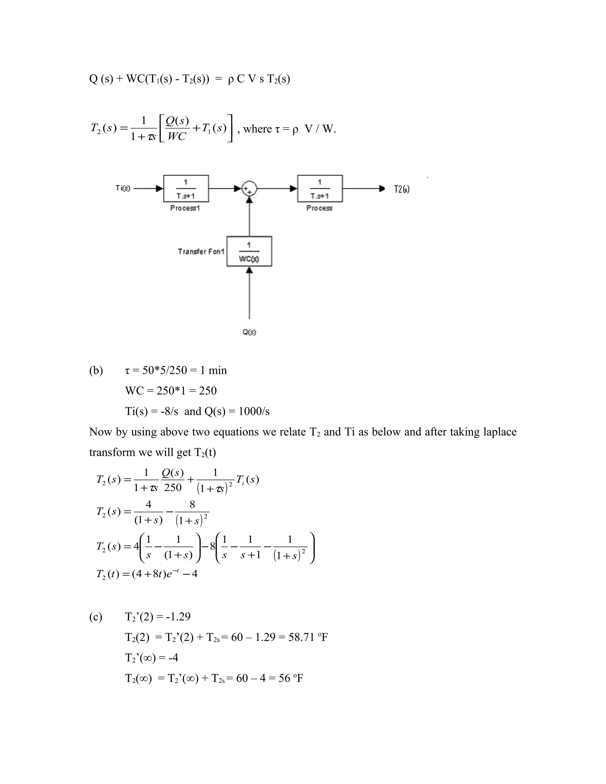
(c) T2’(2) = -1.29
T2(2) = T2’(2) + T2s = 60 – 1.29 = 58.71 oF
T2’(∞) = -4
T2(∞) = T2’(∞) + T2s = 60 – 4 = 56 oF
4.
0.85
T2’(t)
0
0.5
t
-4
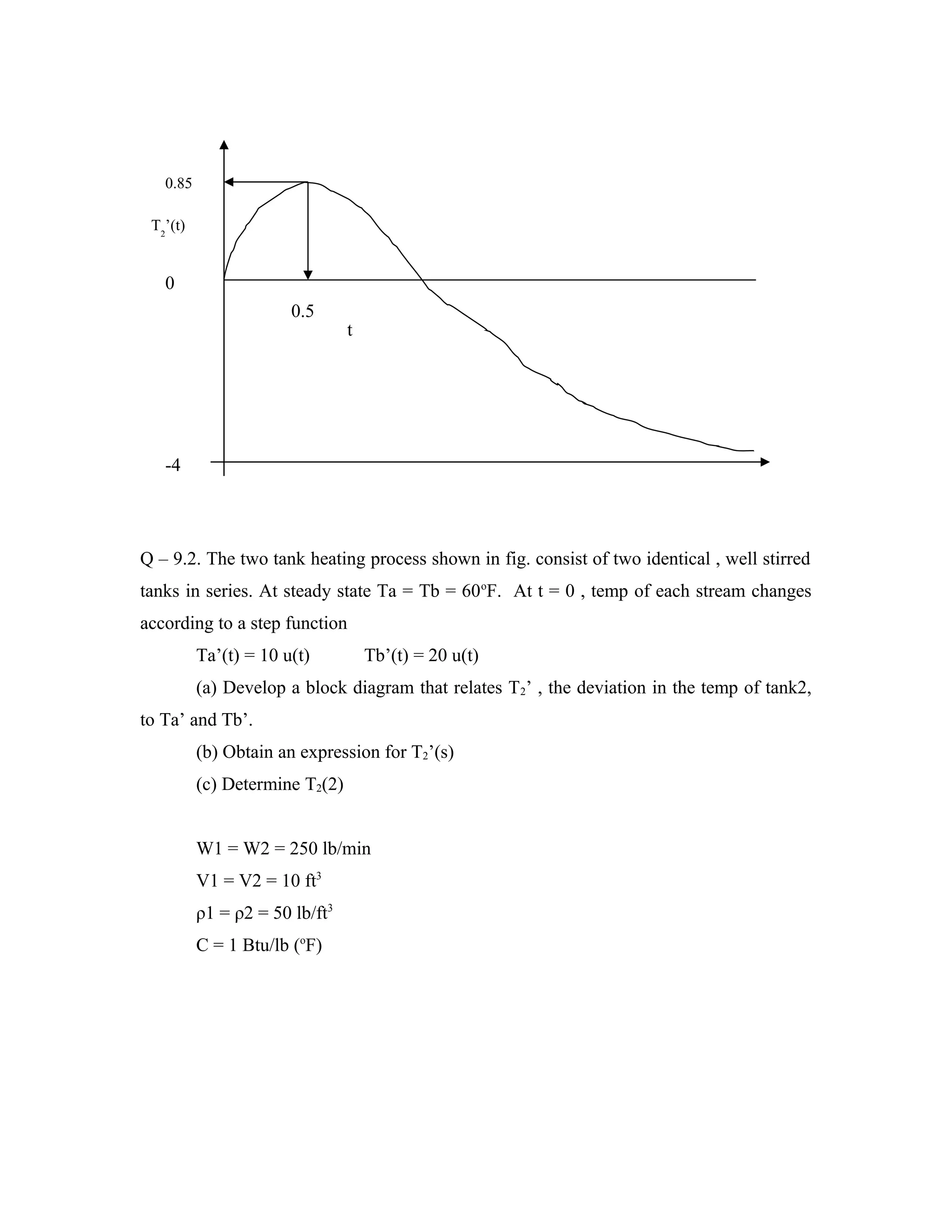
Q – 9.2. The two tank heating process shown in fig. consist of two identical , well stirred
tanks in series. At steady state Ta = Tb = 60 oF. At t = 0 , temp of each stream changes
according to a step function
Ta’(t) = 10 u(t) Tb’(t) = 20 u(t)
(a) Develop a block diagram that relates T 2’ , the deviation in the temp of tank2,
to Ta’ and Tb’.
(b) Obtain an expression for T2’(s)
(c) Determine T2(2)
W1 = W2 = 250 lb/min
V1 = V2 = 10 ft3
ρ1 = ρ2 = 50 lb/ft3
C = 1 Btu/lb (oF)
5.
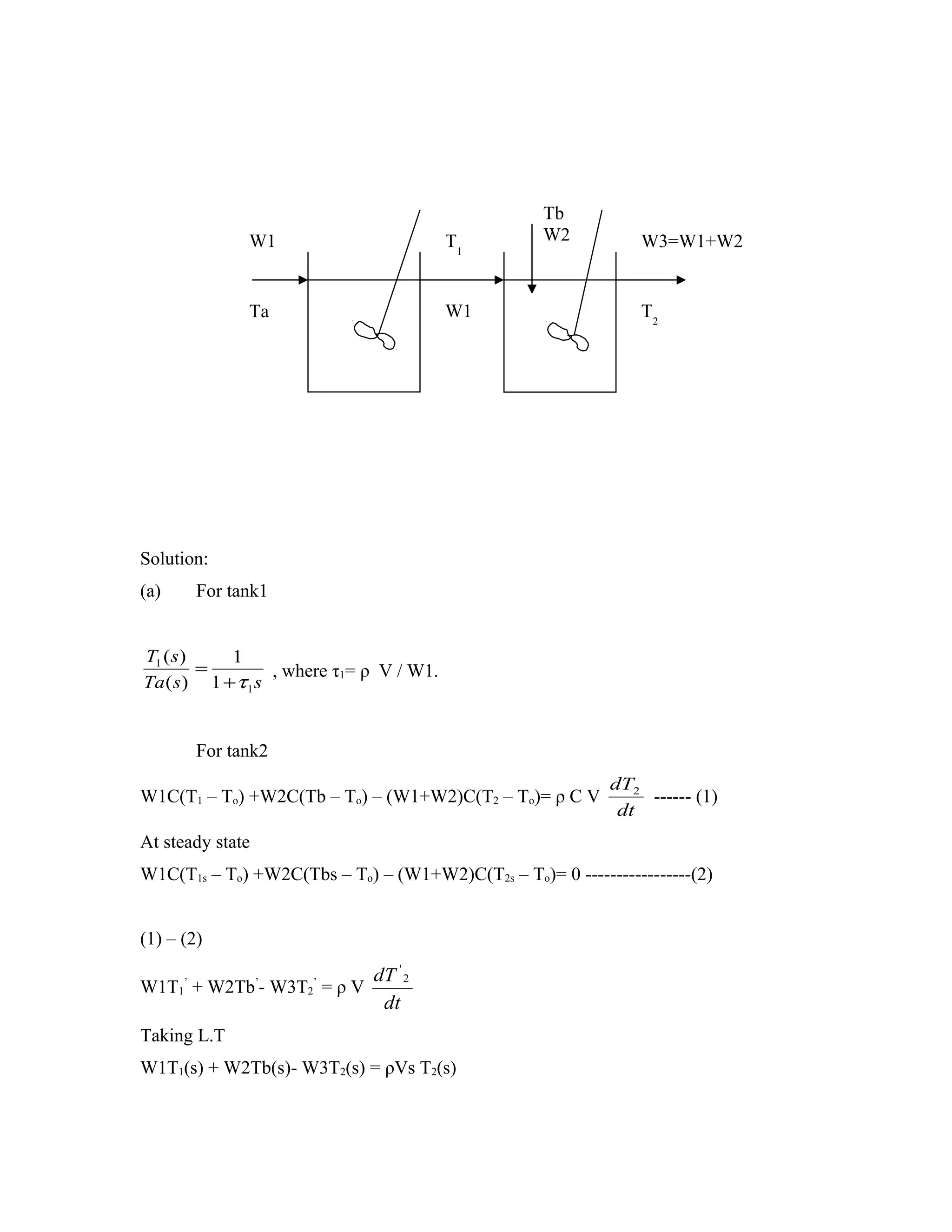
Tb
W1 T1 W2 W3=W1+W2
Ta W1 T2
Solution:
(a) For tank1
T1 ( s ) 1
= , where τ1= ρ V / W1.
Ta ( s ) 1 + τ 1 s
For tank2
dT2
W1C(T1 – To) +W2C(Tb – To) – (W1+W2)C(T2 – To)= ρ C V ------ (1)
dt
At steady state
W1C(T1s – To) +W2C(Tbs – To) – (W1+W2)C(T2s – To)= 0 -----------------(2)
(1) – (2)
dT ' 2
W1T1’ + W2Tb’- W3T2’ = ρ V
dt
Taking L.T
W1T1(s) + W2Tb(s)- W3T2(s) = ρVs T2(s)
6.
T2 ( s) = [
1 W1
1 + τs
T (S ) + W 2
W3 1
]
T ( S ) where τ= ρ V / W3.
W3 b
(b) τ1 = 50*10/250 = 2 min
τ = 50*5/250 = 1 min
W1/W3 = 1/2 = W2/W3
Ta(s) = 10/s and Tb(s) = 0/s
Now by using above two equations we relate T 1 and Ta as below and after taking laplace
transform we will get T2(t)
7.
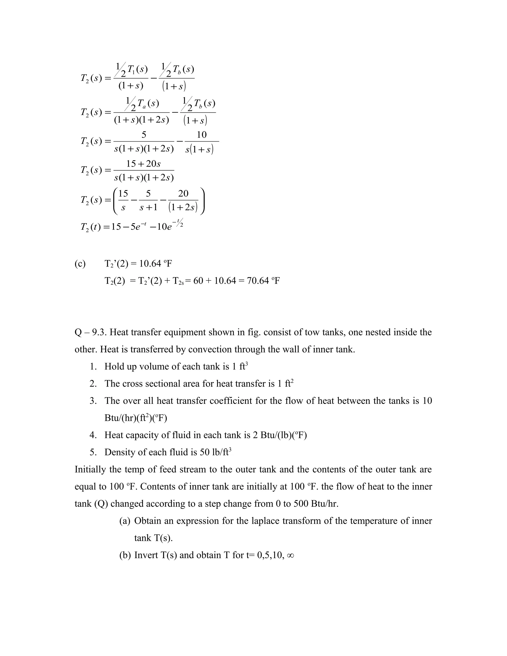
1 T (s)1 T (s)
T2 ( s ) = 2 − 2
1 b
(1 + s ) (1 + s )
1 Ta ( s ) 1 Tb ( s )
T2 ( s ) = 2 − 2
(1 + s )(1 + 2 s ) (1 + s )
5 10
T2 ( s ) = −
s (1 + s )(1 + 2 s ) s (1 + s )
15 + 20 s
T2 ( s ) =
s (1 + s )(1 + 2 s )
15 5 20
T2 ( s ) = −
s s + 1 − (1 + 2 s )
−t
T2 (t ) = 15 − 5e −t − 10e 2
(c) T2’(2) = 10.64 oF
T2(2) = T2’(2) + T2s = 60 + 10.64 = 70.64 oF
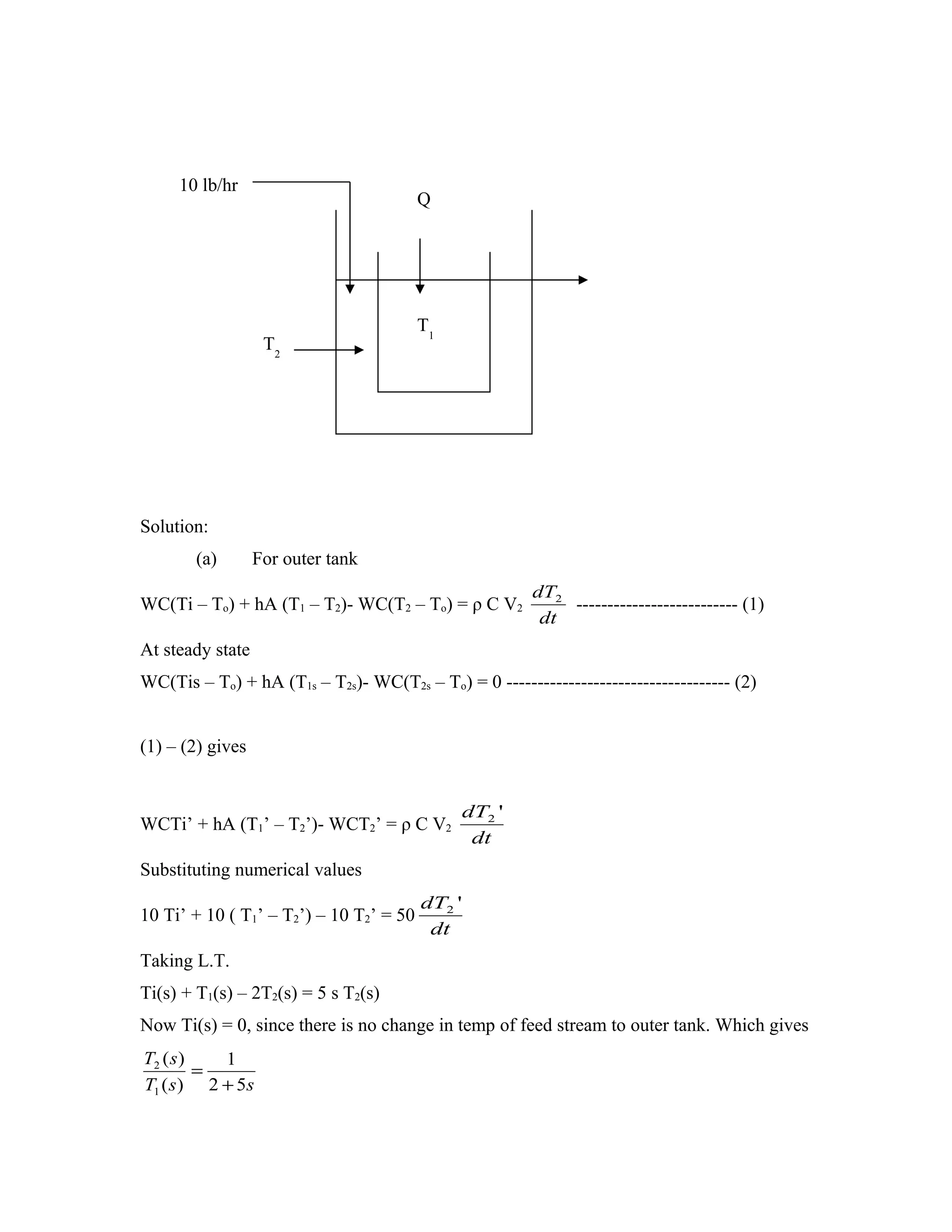
Q – 9.3. Heat transfer equipment shown in fig. consist of tow tanks, one nested inside the
other. Heat is transferred by convection through the wall of inner tank.
1. Hold up volume of each tank is 1 ft3
2. The cross sectional area for heat transfer is 1 ft2
3. The over all heat transfer coefficient for the flow of heat between the tanks is 10
Btu/(hr)(ft2)(oF)
4. Heat capacity of fluid in each tank is 2 Btu/(lb)(oF)
5. Density of each fluid is 50 lb/ft3
Initially the temp of feed stream to the outer tank and the contents of the outer tank are
equal to 100 oF. Contents of inner tank are initially at 100 oF. the flow of heat to the inner
tank (Q) changed according to a step change from 0 to 500 Btu/hr.
(a) Obtain an expression for the laplace transform of the temperature of inner
tank T(s).
(b) Invert T(s) and obtain T for t= 0,5,10, ∞
8.
10 lb/hr
Q
T1
T2
Solution:
(a) For outer tank
dT2
WC(Ti – To) + hA (T1 – T2)- WC(T2 – To) = ρ C V2 -------------------------- (1)
dt
At steady state
WC(Tis – To) + hA (T1s – T2s)- WC(T2s – To) = 0 ------------------------------------ (2)
(1) – (2) gives
dT2 '
WCTi’ + hA (T1’ – T2’)- WCT2’ = ρ C V2
dt
Substituting numerical values
dT2 '
10 Ti’ + 10 ( T1’ – T2’) – 10 T2’ = 50
dt
Taking L.T.
Ti(s) + T1(s) – 2T2(s) = 5 s T2(s)
Now Ti(s) = 0, since there is no change in temp of feed stream to outer tank. Which gives
T2 ( s ) 1
=
T1 ( s ) 2 + 5s
9.
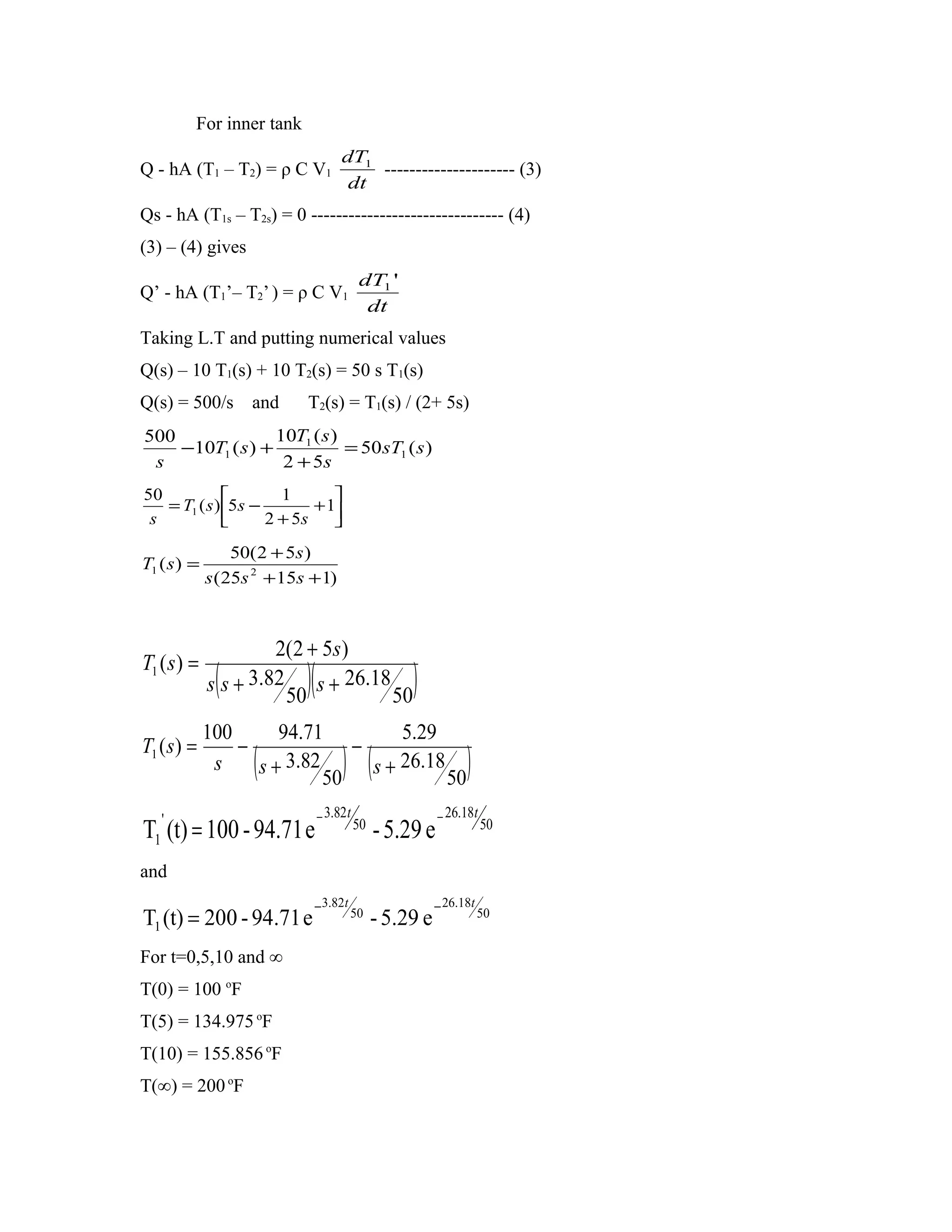
For inner tank
dT1
Q - hA (T1 – T2) = ρ C V1 --------------------- (3)
dt
Qs - hA (T1s – T2s) = 0 ------------------------------- (4)
(3) – (4) gives
dT1 '
Q’ - hA (T1’– T2’ ) = ρ C V1
dt
Taking L.T and putting numerical values
Q(s) – 10 T1(s) + 10 T2(s) = 50 s T1(s)
Q(s) = 500/s and T2(s) = T1(s) / (2+ 5s)
500 10T1 ( s )
−10T1 ( s ) + = 50 sT1 ( s )
s 2 + 5s
50 1
= T1 ( s ) 5s − + 1
s 2 + 5s
50(2 + 5s )
T1 ( s ) =
s (25s 2 + 15s + 1)
2(2 + 5s )
T1 ( s ) =
( )(
s s + 3.82 s + 26.18
50 50
)
100 94.71 5.29
T1 ( s ) = − −
s (
s + 3.82
50
) (
s + 26.18
50
)
' − 3.82 t − 26.18t
T1 (t) = 100 - 94.71 e 50
- 5.29 e 50
and
− 3.82t − 26.18t
T1 (t) = 200 - 94.71 e 50
- 5.29 e 50
For t=0,5,10 and ∞
T(0) = 100 oF
T(5) = 134.975 oF
T(10) = 155.856 oF
T(∞) = 200 oF
![T2 ( s ) = [
1 W1
1 + τs
T (S ) + W 2
W3 1
]
T ( S ) where τ= ρ V / W3.
W3 b
(b) τ1 = 50*10/250 = 2 min
τ = 50*5/250 = 1 min
W1/W3 = 1/2 = W2/W3
Ta(s) = 10/s and Tb(s) = 0/s
Now by using above two equations we relate T 1 and Ta as below and after taking laplace
transform we will get T2(t)](https://image.slidesharecdn.com/tut09-130408181727-phpapp01/75/Tut09-6-2048.jpg)