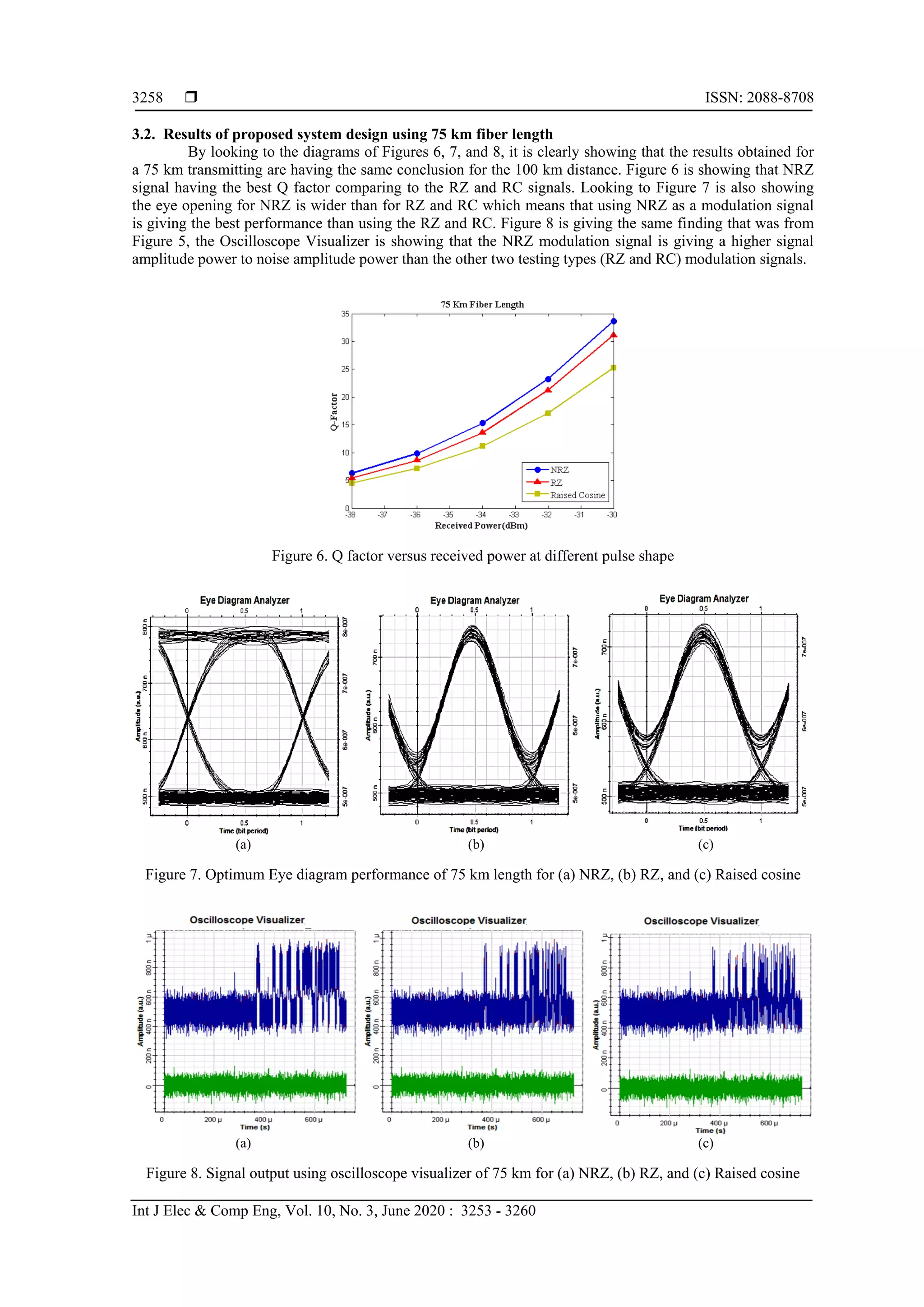
This document presents a study on transmitting audio signals via fiber optics, focusing on the non-linear effects and modulation techniques using MATLAB and OptiSystem. It finds that Non-Return-to-Zero (NRZ) modulation outperforms Return-to-Zero (RZ) and Raised Cosine (RC) modulation in terms of quality-factor (Q-factor), eye diagram performance, and output signal amplitude across distances of 75 km and 100 km. The study emphasizes the challenges of nonlinearity in fiber optics while highlighting NRZ's resilience to noise and superior performance metrics.
![International Journal of Electrical and Computer Engineering (IJECE)
Vol. 10, No. 3, June 2020, pp. 3253~3260
ISSN: 2088-8708, DOI: 10.11591/ijece.v10i3.pp3253-3260 3253
Journal homepage: http://ijece.iaescore.com/index.php/IJECE
Transmitting audio via fiber optics under nonlinear effects and
optimized tuning parameters based on co-simulation of
MATLAB and OptiSystemTM
Abdulrasul A. Al-Hayder, H. J. Abd, Ahmed Samawi Alkhafaji
Department of Electrical Engineering, College of Engineering, Babylon University, Iraq
Article Info ABSTRACT
Article history:
Received Apr 17, 2019
Revised Nov 16, 2019
Accepted Jan 8, 2020
The ability of fiber optic to overcome the signal transmission problems is
making it a dominant transmission medium. Despite of this major positive
attribute of optic fibers, there is still a downside for using the fiber optic
communication; that is the nonlinearity problem. For the first time, a design
of an audio signal is suggested and executed in MATLAB with integration
with OptiSystemTM
Software .The audio signal then transmitted in different
shapes of modulation signals (NRZ, RZ, & RC) for different distances
(100 km & 75 km) via a fiber optic media to be received in a receiving part
of the simulated system. Three tests are used to do so. The first is
the Quality-facto (Q-Factor) against the received power, second test is eye
diagram performance and finally is the measuring of the amplitude of output
(received) signal for each modulation signal shape using the Oscilloscope
Visualizer. The NZR modulation signal was found to be the best one of
the three used signals’ types in all three tests. The Q-factor for NRZ pulse
shape (=12) was higher than that for RZ (=10) and RC (=8) for a 100 km
distance at the same received power level.
Keywords:
Audio signal
Nonlinear effect
NRZ
Q-factor
Raised cosine
Copyright © 2020 Institute of Advanced Engineering and Science.
All rights reserved.
Corresponding Author:
H. J. Abd,
Department of Electrical Engineering, College of Engineering,
Babylon University,
Babil-Hilla, 40 street- center of the city of Hilla, Iraq.
Email: haiderlaser@yahoo.com
1. INTRODUCTION
Since the optical fiber, as a communication medium, is providing a lot more bandwidth than
the copper capacity, it is become the main communication systems medium [1-4]. It is offering low loss over
a high bandwidth, reduction of unwanted alterations, no electromagnetic intervention, and its long life.
Optical fiber and wireless communications are almost complementary, yet, especially at gigabits per second
transmission rates, wireless network having some hindrance to accomplish high end-to-end data delivery
performance. Optical fibers are widely used in communication, sensors, lighting and other usage [5-6].
In communication, optical fibers are providing a long distance and a higher data rates transmission
comparing to other forms. Using copper wires in communication is less efficient than the optical fibers in
long distances transmission besides the better immunity that the optical fibers provide against
the electromagnetic interference. Optical fibers also provide a 100% signal security comparing to the copper
cables [7-10]. The fibers are not emitted the transmitted signals without tampering while the copper cable
dose, this fiber property preventing the drawing of transmitted signal. The non-linear behavior of optical fiber
is its major weakness [11-20]. This nonlinearity is a directly proportional with the power of the signal been
transmitted through the fiber optic. At the increasing of the light power, the nonlinearity behavior
is becoming out of control and the probability of both distorting the transmitted signal and degrading
the system efficiency may be raised [21-22]. There is also a higher chance of a signal interference as a result](https://image.slidesharecdn.com/v51195568jan16nov1917apr19ez-201211023009/75/Transmitting-audio-via-fiber-optics-under-nonlinear-effects-and-optimized-tuning-parameters-based-on-co-simulation-of-MATLAB-and-OptiSystem-1-2048.jpg)
![ ISSN: 2088-8708
Int J Elec & Comp Eng, Vol. 10, No. 3, June 2020 : 3253 - 3260
3254
of the non-linearity. When these signals are transmitted in an equally spaces’ separated channels will create
what is called the four-wave mixing (FWM). Suppressing the FWM in optical communication is improving
the system efficiency, which is a high priority goal. Several techniques been done to achieve an effective
reduction of FWM. Wavelength swept WDM, the allocation of polarization and effective frequency,
WDM/TDM (wavelength/time division multiplexing), and non-uniform spacing of channels ware
applied [23-30]. These techniques are needing an extra complexity in system design or at least needing
a compensator to improve the signal dispersion. Some of these techniques are negatively effecting the WDM
capacity in order to compress the FWM.
The modulation technique used is influencing the signal’s interference, which is occurring when
FWM is used. The transmission of audio signal via optical fiber under the non-linear conduct is not yet
investigated. The goal of this paper is to study the transmission of audio signal via fiber optic at a non-linear
state and different modulation signals to find the best one for satisfied system performance. For this purpose,
a system to simultaneously transmitting and receiving an audio signal via a fiber optic cable at its non-linear
behavior is designed and implemented using the MATLAB and OptiSystem simulation model. The proposed
system performance is tested for different types of modulation signals to get the best one.
2. MODELING OFAUDIO SIGNAL AND SIMULATION SYSTEM DESIGN
The system that designed for this work is highlighted in this section. It is simulated using MATLAB
integrated with OptiSystemTM
. The simulated system of this work was designed and studied in three steps.
The first is designing and implementing the new audio communication signal in MATLAB and integrated it
into the OptiSystemTM
. The audio signal of the parameters shown in Table 1 then simulated with the fiber
link as a second step. The third step is to study the performance of the optical signal under two transmission
lengths (100 km and 75 km) for different pulse shapes modulation signals such as Non-Return-Zero (NRZ),
Return-Zero (RZ) and RC (Raised Cosine). The design of the transmitter and receiver of the model is shown
in Figures 1 and 2.
The transmitter part consists of an array of a continuous-wave (CW) produced by laser sources
connected to an external modulator. The channel frequency is set to 193 THz. The external modulator is
consisting of a Pseudo–Random Bit Sequence (PRBS) generator connected to a pulse generator to modulate
the optical signals using different pulse shapes (NRZ, RZ, and RC) modulation signals which is connected
to Mach-Zehnder modulator (MZM) acting as an intensity modulator. A single mode fiber is used as
an optical link.
At the receiver, the de-multiplexer splits the collected frequencies. The PIN photo diode is detecting
the signal with a responsively () of 0.8 A/W and a dark current of 10 nA. The signal is then passed through
the low-pass Bessel filter, which is also linked, to the BER analyzer that is used to generate the graph.
The system's parts (transmitter, optical channel and receiver) are shown in Figures 1 and 2, and it is
parameters are explained in Table 2.
Figure 1. Full circuit diagram](https://image.slidesharecdn.com/v51195568jan16nov1917apr19ez-201211023009/75/Transmitting-audio-via-fiber-optics-under-nonlinear-effects-and-optimized-tuning-parameters-based-on-co-simulation-of-MATLAB-and-OptiSystem-2-2048.jpg)
![Int J Elec & Comp Eng ISSN: 2088-8708
Transmitting audio via fiber optics under nonlinear effects and optimized… (Abdulrasul A. Al-Hayder)
3255
Figure 2. Optical simulation system design
Table 1. Audio signal properties
Parameter Unit Values
File Format Wave Sound (.wav) -
filename story.wav -
Bit Rate, B kbps 141
Number of channels n 2
Sample Rate, Fs Hz 44100
Queue duration Seconds 10
Frame size Sample 1024
Output data type double -
Channel type - Stereo
load file to OptiSystemTM
mat
Type of media path Online media -
Table 2. System parameters
Parameter Unit Values
Fiber length, L km 75-100
Input power, Pi dBm (-20) to (-12)
Input frequencies THz 193
Dispersion, Dc ps/nm.km 17 for SMF
Dispersion slope S ps/nm2.km 0.075 for SMF
Cross effective area, Aeff m2 80 for SMF
Third order susceptibility, X111 m3/w. s 6×10-15
Refractive index, n - 1.48
Speed of light, c (m/s) 3×10⁸
Attenuation factor, (dB/ km) 0.2
Number of channels - 1
Receiver noise temperature, Tn K 300
Receiver load resistor, RL 1030
Schrödinger Equation (NLSE) is used to explain the envelope of the optical field when the nonlinear
effects are in the form that is given by the following equation [12],
2 3
2
1 2 32 3
, , , ,1
( , ) ( , ) ( , ).
2 2 6
A z t A z t A z t A z tj
A z t B B B j A z t A z t
z t t t
(1)
where A, is the wave-field envelope, α is the fiber loss factor, B1, B2, and B3 are the dispersion factors and
is the nonlinear constant.](https://image.slidesharecdn.com/v51195568jan16nov1917apr19ez-201211023009/75/Transmitting-audio-via-fiber-optics-under-nonlinear-effects-and-optimized-tuning-parameters-based-on-co-simulation-of-MATLAB-and-OptiSystem-3-2048.jpg)
![ ISSN: 2088-8708
Int J Elec & Comp Eng, Vol. 10, No. 3, June 2020 : 3253 - 3260
3256
To assess the system performance under the impact of nonlinear effect, which is the FWM crosstalk,
and with other noise types, we should add the FWM crosstalk expressions as in (2),
III s
iik
I s
ijkm
IM
P
P
P
P
C
4
1
8
1)(
(2)
where
)(m
IMC is the FWM crosstalk effective in intensity modulation-direct detection (IM-DD) transmission.
Note that the probability of transmit bit “1” at any time for every user is 1 2⁄ . Equation (3) explaining
the relationship between the shot noise power (the left side) and the thermal noise power (the right side) [31]:
L
nbsr
R
BTK
N
WPeB 42
(3)
where, Psr is a received peak power of the signal light, B electrical bandwidth of the receiver, is
the detector responsivity, e is the Electron’s charge, Kb Boltzmann’s constant, Tn Absolute receiver noise
temperature, RL Receiver load resistor. The average SNR (4) is calculated from (2) and (3) [31]:
IMs
L
nbsr
sr
CPK
R
BTK
N
WPeB
N
WP
SNR
22
2
2
4
(4)
Then BER is calculated in (5),
,
82
1
SNR
erfcPBER e (5)
and (6) is to find the Q-factor,
22
1 Q
erfcBER (6)
3. RESULTS AND ANALYSIS
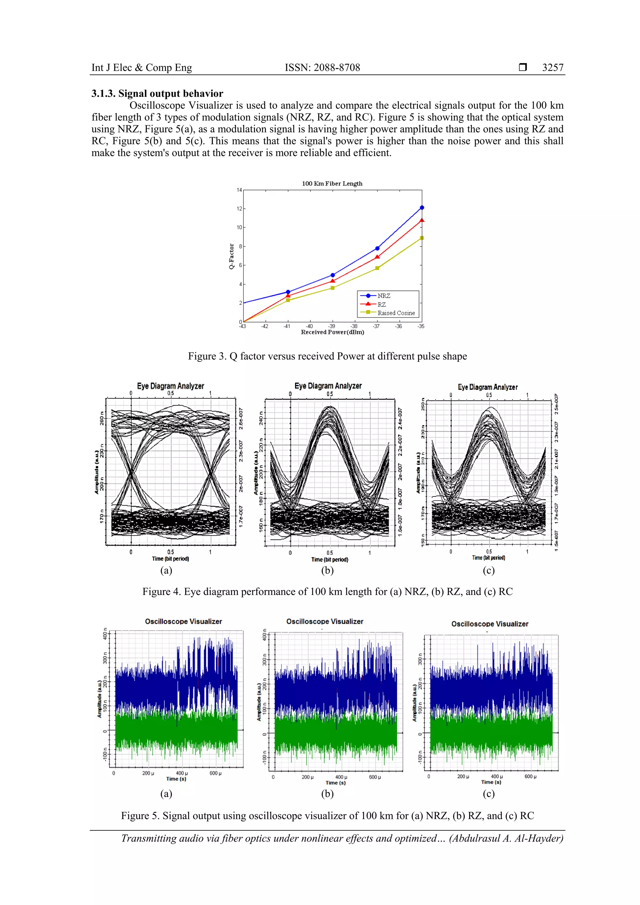
This section is showing the finding of this work with analysis. The following results are obtained
from the simulated system using transmission distances of 100 km and 75 km fiber length for 3- pulse's
shapes NRZ, RZ, and RC for each distance:
3.1. Results of proposed system design using 100 km fiber length
3.1.1. Received power versus Q-factor
The relationship between the Received power and Q-factor under the effect of nonlinearity for
different pulse shaping is shown in Figure 3. The optical input power is started at -20 dBm and increased by
a step of 1 dBm till -12 dBm as a final input power. The obtained results are showing that the Q-factor
is increased for the increasing in the received power for all shapes of pulses, however the system's behavior
is different for different modulation signals under a nonlinear effect. The best value of Q-factor 12 was
obtained when NRZ modulation signal is used at a received power of (-35 dBm). In the case of the RC
modulation signal, Q-factor is a minimum (only in the range of 8) at the same received power (-35 dBm).
For RZ pulses, the Q-factor is 10 which is in between the two previous values under the same conditions.
This means that the NRZ gives a high resistance to the nonlinear effect in comparing with other two types.
3.1.2. Eye diagram performance
Figure 4 is showing the eye diagrams performances of the proposed system's approach taken at ch1
at Pin = -14 dBm. It is clear that using NRZ pulses, shown in Figure 4(a), is having wider eye opening which
means a better performance and a higher invulnerability to noise comparing to the other two modulating
signals as shown in Figures 4(b) for RZ and 4(c) for RC modulation signals.](https://image.slidesharecdn.com/v51195568jan16nov1917apr19ez-201211023009/75/Transmitting-audio-via-fiber-optics-under-nonlinear-effects-and-optimized-tuning-parameters-based-on-co-simulation-of-MATLAB-and-OptiSystem-4-2048.jpg)
![Int J Elec & Comp Eng ISSN: 2088-8708
Transmitting audio via fiber optics under nonlinear effects and optimized… (Abdulrasul A. Al-Hayder)
3259
4. CONCLUSION
The transmission of audio signal through Optical fiber system was designed and performed for first
time using Co-Simulation of MATLAB integrated with OptiSystem14TM
. The system was tested for different
types of pulse shapes (NRZ, RZ, and RC) modulation signals and for different distances 100km and 75 km of
fibers lengths. Different parameters were studied and analyzed and the system was found to be having
the best performance with NRZ modulation signal comparing to the other two (RZ and RC) for all three
parameters and both distances. The Q factor, which is an efficiency indicator, is more when NRZ signal
is used as a modulation signal 12 for a -35 dBm received power while it is 10 for RZ and 8 for RC at
the same power for a 100 km of transmitting distance. The eye opening is also wider for NRZ than that for
RZ and RC, which means that NRZ modulation pulse, is more resistive to noise. For a 75 km fiber
transmitting distance, the conclusion has no difference than that for a 100 km distance. The eye opening in
case of using NRZ as a modulation signal is wider than using other two types (RZ and RC). The Oscilloscope
Visualizer is showing that the use of NRZ is having more confident than the use of RZ and RC because it is
having a higher amplitude, which means that the ones and zeros of the received signals could be easily,
differentiated when NRZ modulation signal is used comparing to the other two tested modulation signals
(RZ and RC).
ACKNOWLEDGEMENTS
This work was implemented in the laboratories of our Electrical Engineering Department of
the University of Babylon/Engineering College. Our regards and thankful to the staff, department’s head and
the college dean for the help and support.
REFERENCES
[1] B. N. Mohapatra, "Audio transmitter and receiver system using fiber optic cable," International Journal of
Emerging Technologies in Engineering Research, vol. 5, no. 5, May 2017.
[2] G.P. Agrawal, "Fiber Optic Communication Systems," John Wiley & Sons, New York, 2002
[3] C. C. Yang, "Code space enlargement for hybrid fiber radio and baseband OCDMA PONs," Journal of Light wave
Technology, vol. 29, no. 9, pp. 1394-1400, 2011.
[4] S. Zeadally and L. Zhang, "Enabling gigabit network access to end users," Proceedings of the IEEE, vol. 92, no. 2,
pp. 340–353, 2004.
[5] R. Ramaswami, K. Sivarajan, and G. Sasaki, "Optical networks: a practical perspective," Morgan Kaufmann, 2009.
[6] G. Farrell, Q. Wang, and W. Yan, "Investigation on single mode–multil mode–single mode fiber structure," Journal
of Light Technology, vol. 26, no. 5, 2008.
[7] O. Ziemann, J. Krauser, P. E. Zamzow, and W. Daum, "POF-polymer optical fibers for data communication,"
Springer Science & Business Media, 2013.
[8] J. Zubia and J. Arrue, "Plastic optical fibers: An introduction to their technological processes and applications,"
Optical Fiber Technology, vol. 7, no. 2, pp. 101–140, 2001.
[9] T. Morioka, Y. Awaji, R. Ryf, P. Winzer, D. Richardson, and F. Poletti, "Enhancing optical communications with
brand new fibers," IEEE Communications Magazine, vol. 50, no. 2, pp. s31-s42, 2012.
[10] A.K. Sharma, R.K. Sinha, S.K. Sharma, S.K. Arya, R.S. Kaler, "Improved small signal analysis for dispersive
optical fiber communication systems," J. Opt. Commun., pp. 1-6, 2004.
[11] H. J. Abed, N. M. Din, M. H. Al-Mansoori, H. A. Fadhil, and F. Abdullah, "Recent four-wave mixing suppression
methods," Optik, vol. 124, no. 15, pp. 2214–2218, 2013.
[12] H. J. Abd, M. H. Al-Mansoori, N. M. Din, F. Abdullah, and H. A. Fadhil, "Priority-based parameter optimization
strategy for reducing the effects of four-wave mixing on WDM system," Optik, vol. 125, no. 1, pp. 25-30, 2014.
[13] H. Abd, et al., "Four-wave mixing crosstalk suppression based on the pairing combinations of differently linear-
polarized optical signals," The Sci. World J., vol. 2014, pp. 1-10, 2014,
[14] H. J. Abd, M. H. Al-Mansoori, N. M. Din, F. Abdullah, and H. A. Fadhil, "Four-wave mixing reduction technique
based on smart filter approach," International Journal of Electronics, vol. 102, no. 6, pp. 1056–1070, 2015.
[15] N.M. Ridzuan, M.F.L. Abdullah, M.B. Othman and M.B. Jaafar, "A carrier less amplitude phase (CAP) modulation
format: Perspective and prospect in optical transmission system," International Journal of Electrical and Computer
Engineering (IJECE), vol. 8, no. 1, pp. 585-595, Feb. 2018.
[16] N. Salim, H.J. Abd, A.N. Aljamal, and A.H. Jaber, "Four-wave mixing suppression method based on odd-even
channels arrangement strategy," Progress In Electromagnetics Research, vol. 66, pp. 163-172, 2018.
[17] B. Patnaik and P.K. Sahu, "Novel QPSK modulation for DWDM free space optical communication system," 21st
Annual Wireless and Optical Communications Conference (WOCC), pp. 170-175, 2012.
[18] M.A. Shah, S. Abd Latiff, and Riaz T., "Performance measurement of free-space optical 980 nm channel using
multiple sets of environmental conditions," Wireless Personal Communication, vol. 85, no. 2, pp. 345-357, 2015.
[19] V.G.A. Carneiro, G.K. Rodrigues, M. Thereza, and M.R. Giraldi, "Performance analysis of a 2D double
hard-limited OCDMA system over FSO link under strong turbulence for defense applications," Military
Communications Conference, MILCOM, pp. 1-6, 2012.](https://image.slidesharecdn.com/v51195568jan16nov1917apr19ez-201211023009/75/Transmitting-audio-via-fiber-optics-under-nonlinear-effects-and-optimized-tuning-parameters-based-on-co-simulation-of-MATLAB-and-OptiSystem-7-2048.jpg)
![ ISSN: 2088-8708
Int J Elec & Comp Eng, Vol. 10, No. 3, June 2020 : 3253 - 3260
3260
[20] R.A. Fayadh, M.K. Wali, and M.F. Bonneya, "Establishment network by using FSO link based on MD code for
hybrid SCM-SAC-OCDMA wireless system," International Journal of Electrical and Computer Engineering
(IJECE), vol. 8, no. 6, pp. 5107-5117, Dec. 2018.
[21] A.R. Chraplyvy, "Limitations on lightwave communications imposed by optical fiber nonlinearities," J. Lightw.
Technol., vol. 8, no. 10, pp. 1548–1557, 1990
[22] X. Feng, F. Poletti, A. Camerlingo, F. Parmigiani, P. Petropoulos, P. Horak, G.M. Ponzo, M. Petrovich, Jindan Shi,
W.H. Loh, and D.J. Richardson, "Dispersion controlled highly nonlinear fibers for all-optical processing at
telecoms wavelengths," Optic. Fiber Technology, vol. 16, no. 6, pp. 378–391, 2010.
[23] T. Taniguchi, N. Sakurai, H. Kimura, K. Kumozaki, "Experimental demonstration of tolerance to FWM in crosstalk
in wavelength–swept WDM access systems," IECE Electronics Express, vol. 6, no. 16, pp. 1180-1185, 2009.
[24] P. J. Winzer and R. J. Essiambre, "Advanced optical modulation," Proc. ECOC, Rimini, Italy, Invited paper
Th2.6.1, pp. 1002–1003, 2003.
[25] A. Gnauck and P. Winzer, "Optical phase-shift-keyed transmission," Journal of Lightwave Techno., vol. 23, no. 1,
pp. 115–130, 2005.
[26] R.S. Kaler, A.K. Sharma, and T.S. Kamal, "Simulation results for four wave mixing in an optical fiber near zero
dispersion wavelength," J. Electron.Teclnol., vol. 85, pp. 31-36, Jul. 2004.
[27] U. Stanley, V.M. Olu, C. Ochonogor, A. Peter, and A. Francis, "Experimental analysis of cable distance effect on
signal attenuation in single and multimode fiber optics," International Journal of Electrical and Computer
Engineering (IJECE), vol. 8, no. 3, pp. 1577-1582, Jun. 2018
[28] M. Aljanabi, "Resonance frequency analysis of laser optical fiber based on micro cantilever," International Journal
of Electrical and Computer Engineering (IJECE), vol. 9, no. 4, pp. 3090-3099, Aug. 2019.
[29] K.S. Alaoui, J. Foshi, and Y. Zouine, "Radio over fiber system based on a hybrid link for next generation of optical
fiber communication," International Journal of Electrical and Computer Engineering (IJECE), vol. 9, no. 4,
pp. 2571-2577, Aug. 2019.
[30] A. Shaban, M. O. Abed, E. A. Hussein, and H. J. Abd, "Durability of modulation technique to channel crosstalk
effect in optical communication link via applying high data rate," International Journal of Electrical and Computer
Engineering (IJECE), vol. 10, no. 1, pp. 5107-5117, 2019.
[31] T.H. Abd, S.A. Aljunid, H.A. Fadhil, R.A. Ahmad, and N.M. Saad, "Development of a new code family based on
SAC-OCDMA system with large cardinality for OCDMA network," Optical Fiber Technology, vol. 17, no. 4,
pp. 273-280, 2011.
BIOGRAPHIES OF AUTHORS
Associate professor Dr. Haider .J. Abd earned his Ph.D. in the field of Electrical Engineering
from university of Tenaga Nasional, Malaysia, 2014. He has more than ten years of experience in
teaching. He completed his MSc, in Electrical Engineering, university of Baghdad, Baghdad, Iraq,
2005. His research interests includes optical fiber communication, Wireless communication,
Digital signal processing, smart systems, Biomedical Engineering, Maglev system and Adaptive
control system.
Abdulrasul A. Al-Hayder earned his M.sc in the field of Electrical Engineering from university
of technology, Iraq, 1990. He has more than five years of experience in teaching.
He completed his BSc in Electrical Engineering, university of technology, Baghdad, Iraq, 1981.
His research interests include communication, wavelet transform, electronic system design and
Quantum communication.
Ahmed Samawi Alkhafaji earned his M.sc in the field of Electrical and Electronic Engineering
from Eastern Mediterranean University, Turkey/North Cyprus2013. He has more than five years of
experience in teaching. He completed his B.Sc in Electrical Engineering, university of technology,
Baghdad, Iraq, 2001. His research interests includes power electronics, control power system,
electronic system design and predictive current control modeling.](https://image.slidesharecdn.com/v51195568jan16nov1917apr19ez-201211023009/75/Transmitting-audio-via-fiber-optics-under-nonlinear-effects-and-optimized-tuning-parameters-based-on-co-simulation-of-MATLAB-and-OptiSystem-8-2048.jpg)