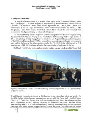
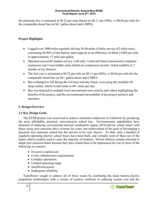
SlideShare a Scribd company logo
Economical Electric School Bus (EESB)
Final Project Report – June 2, 2014
Economical Electric School Bus EESB
Final Report June 2nd
, 2014
2
Table of Contents
Table of Figures.......................................................................................................................... 3 
1.0 Executive Summary.................................................................................................................. 4 
Project Highlights ........................................................................................................................... 5 
2. Design Overview ........................................................................................................................ 5 
2.1 Key Design Goals ................................................................................................................. 5 
2.2 Technologies and Methods Implemented............................................................................. 6 
2.3 Bus Vehicle Utilized............................................................................................................. 8 
2.4 Component Selection............................................................................................................ 8 
3. Vehicle Integration.................................................................................................................... 10 
3.1 Main Propulsion System..................................................................................................... 10 
3.2 Inverter-Charger Subsystem ............................................................................................... 12 
3.3 Energy Storage Subsystem ................................................................................................. 14 
3.4 Electrically-Driven Accessory Subsystem.......................................................................... 16 
3.5 Vehicle Control Subsystem................................................................................................. 17 
4. Bus Testing and Evaluation ...................................................................................................... 18 
4.1 CHP Approval Process ....................................................................................................... 18 
5.0 In-Service Demonstration....................................................................................................... 25 
5.1 School System Integration.................................................................................................. 25 
5.2 Charging Energy Efficiency and Cost ................................................................................ 27 
Chart showing kWh per mile in the first weeks of service at EUHSD..................................... 28 
5.3 Project Media Coverage...................................................................................................... 29 
5.4 Project Lessons Learned ..................................................................................................... 29 
6.0 Conclusion .............................................................................................................................. 30
7.0 Acknowledgements..…………………………………………………………………………31
Economical Electric School Bus EESB
Final Report June 2nd
, 2014
3
Table of Figures
Figure 1: TransPower Electric School Bus showing battery compartments to Del Lago Academy
of Applied Science.......................................................................................................................... 4
Figure 2. Saf-T-Liner HDX chassis................................................................................................ 8
Figure 3: EESB Component Layout and Energy Flow.................................................................. 9
Figure 4: EESB Motive Drive, 150 kW Motor connected to 7 Speed Eaton Transmission........... 9
Figure 5. Motor-transmission assembly used in EESB prototype................................................ 11
Figure 6. View of main drive motor, transmission, and retarder from underside of bus.............. 12
Figure 7. Drive components integrated into engine compartment; ICU is directly above drive
motor, central control module is to the left, and electrically-driven braking and steering elements
are to the right............................................................................................................................... 13
Figure 8. One of seven Mile-Max™ modules installed into EESB prototype. ........................... 14
Figure 9. Battery modules mounted in one side of EESB prototype luggage compartment. ....... 15
Figure 10. Close-up view of electrically-driven accessory components. ..................................... 16
Figure 11. Dashboard of EESB prototype. ................................................................................... 17
Figure 12: Completed bus............................................................................................................. 18
Figure 13: Battery compartment inspection.................................................................................. 18
Figure 14. Battery compartment. .................................................................................................. 19
Figure 15. Powertrain.................................................................................................................... 19
Figure 16. Professional Engineering Stamp regarding vehicle conversion manual ..................... 25
Figure 17. EUHSD Route and Elevation Profile .......................................................................... 26
Figure 18. EESB Plugged In at CVUSD using same 208VAC panel as used for DPFs ............. 27
Figure 19. EUHSD kWh meter..................................................................................................... 27
Figure 20. EESB Daily Miles and kWh/mi AC in first weeks at EUHSD................................... 28
Figure 21. EESB Featured in San Diego Union Tribune.............................................................. 29
Figure 22. EESB at EUHSD Bus Yard......................................................................................... 29
Economical Electric School Bus EESB
Final Report June 2nd
, 2014
4
1.0 Executive Summary
The purpose of this document is to provide a final report on the Economical Electric School
Bus (EESB) project. The EESB project was implemented by TransPower with funding from the
California Air Resources Board under Grant Agreement No. G11-AQIP-03, which was
administered by the San Diego Air Pollution Control District under Contract No. 541934. Under
this project, a new 2008 Thomas Built HDX Transit Style School Bus was converted from
conventional diesel power to plug-in battery-electric power.
The advanced battery-electric propulsion system developed for this bus was designed during
the second half of 2012 and developed and installed into the bus during the first eight months of
2013. Drive testing of the prototype bus was initiated in late August 2013 and, under the auspices
of the California Highway Patrol (CHP), a series of road tests and sequential safety improvements
were made to the bus over the subsequent six months. On Feb 12, 2014, the vehicle received CHP
approval and a CHP 292 certificate, allowing for transportation of students with the bus.
On March 17, 2014, the prototype bus initiated student service with Escondido Union High
School District, continuing to operate at this location for the planned period of one month. On
April 28 the bus initiated student transportation services with the Cajon Valley Unified School
District in El Cajon, CA. During these trials, the bus logged more than 1,600 miles during eight
weeks of passenger service, regularly operating for 30-40 miles each day. The bus utilized
approximately 60-80% of its rated battery capacity each day with an operating efficiency of about
2 kWh per mile, which equates to approximately 17 miles per gallon. The equivalent fuel cost for
Figure 1: TransPower Electric School Bus showing battery compartments to Del Lago Academy
of Applied Science
Economical Electric School Bus EESB
Final Report June 2nd
, 2014
5
the prototype bus is estimated at $0.22 per mile (based on $0.11 per kWh), vs $0.66 per mile for
the comparable diesel bus (at $4 / gallon diesel and 6 MPG).
Project Highlights
 Logged over 2000 miles regularly driving 30-40 miles of daily service (62 miles max),
consuming 60-80% of the battery rated capacity at an efficiency of about 2 kWh per mile
or approximately 17 miles per gallon.
 Operated successful student service, with only 1 road call (loose transmission computer
connector) and 2 unavailable starts (failed air compressor inverter, failed seatbelt) in 2
months at two districts
 The fuel cost is estimated at $0.22 per mile (at $0.11 per kWh), vs $0.66 per mile for the
comparable diesel bus (at $4 / gallon diesel and 6 MPG)
 Bus recharged to full during the 4-6 hour mid-day break, even using the available 60
Amp outlets, which would relate to 80+ miles per day.
 Bus was featured in multiple local and national news articles and videos highlighting the
benefits of the project, and the environmental stewardship of the project partners and
operators.
2. Design Overview
2.1 Key Design Goals
The EESB project was conceived to achieve emissions reductions in California by producing
the most affordable, practical, zero-emission school bus. Environmental stakeholders have
dreamed of replacing conventional internal combustion engine (ICE)-driven school buses with
buses using zero emission drive systems for years, but achievement of the goal of developing a
practical zero emission school bus has proven to be very elusive. To date, only a handful of
regularly-operating electric school buses have been built, and virtually none of these are of the
larger vehicle models used to carry the majority of students. School districts remain reluctant to
adopt zero emission buses because they have found them to be impractical for one or more of the
following six reasons:
 Excessive capital cost
 Costly infrastructure requirements
 Complex operations
 Limited operating range
 Insufficient power
 Inadequate reliability
TransPower sought to address all of these issues by combining the latest battery-electric
propulsion technologies with a variety of creative solutions to reducing system cost and the
Economical Electric School Bus EESB
Final Report June 2nd
, 2014
6
complexity of transit bus operations. Table 1 summarizes the design goals the EESB project
pursued to address each of the six obstacles to zero emission bus adoption listed above.
Table 1. Design goals for addressing barriers to zero emission school bus adoption.
Barrier to
Adoption
Design Goals to Address Barrier
Excessive capital
cost
Utilize low cost batteries and motors already manufactured in high volume, and combine the
functions of the inverter and battery charger to reduce parts counts.
Costly
infrastructure
requirements
Use advanced power electronics technologies to shrink the size of the battery charger,
enabling it to be mounted on the bus. This eliminates the need for off-board charging
infrastructure. Reliance on battery energy as opposed to hybrids (which still require fuel)
eliminates the need for a refueling infrastructure.
Complex
operations
Sufficient batteries are used to allow the bus to complete its duty cycle without “opportunity
charging” in the middle of the route. Battery charging is required only at the completion of
each duty cycle and is simplified by having the charger mounted on board the vehicle.
Limited operating
range
High energy lithium-ion batteries are used to maximize operating range per weight of
battery used, and large battery packs are employed to maximize the amount of stored energy
on board the bus, increasing its range.
Insufficient power High-performance drive motors and a robust automated manual transmission are used in
tandem to provide high torque and power, supplied in ample quantity by the large battery
pack and high-power Inverter-Charger Unit (ICU).
Inadequate
reliability
The battery-electric propulsion architecture is comparatively simple, with fewer moving
parts than a conventional ICE or hybrid bus. This, along with high-quality component
engineering and integration, will result in a bus with high reliability and low maintenance
costs.
The EESB project was undertaken with the belief that if these design goals could be met, the
project could have a transformative effect on the school bus market. Development of a practical
zero-emission school bus has been a long-sought goal of the California Air Resources Board
(ARB) and other regulatory agencies. It was believed that successful demonstration of the EESB
buses in San Diego County could lead to widespread adoption of such vehicles. The following
subsections describe the engineering achievements of the EESB project in more detail.
2.2 Technologies and Methods Implemented
The key enabling technologies for the EESB project, and the methods implemented, relate to
the components of TransPower’s “ElecTrans™” electric drive system and how they are integrated
into a robust vehicle architecture. ElecTrans™ is an adaptation of a proven battery-electric drive
system, “ElecTruck™,” which uses a new high-power electric drive technology that was
demonstrated concurrently with the EESB project in initial fleet of Class 8 electric drayage trucks
and yard tractors. Therefore, the EESB engineering approach was to leverage and build logically
Economical Electric School Bus EESB
Final Report June 2nd
, 2014
7
on several related technology demonstrations. From a purely technical standpoint, the
ElecTrans™ system to be installed into the EESB prototype was very similar to the drive systems
installed into TransPower’s other vehicles, reducing project risks. Since all of TransPower’s
targeted vehicle applications involve large vehicles that operate locally and perform lots of stop-
and-go driving, school buses represent an attractive new adaptation of this zero-emission
propulsion system. Table 2 lists the basic operating specifications established at the outset of the
EESB project for the school bus variant of the ElecTrans™ system.
Table 2. EESB bus operating specifications.
Operating Parameter Value
Operating Range (miles) 50-75
Maximum Speed Up to 60 mph
Gradability Sustained speed of 40 mph on a 2.5% grade and 10 mph on a 16% grade
Acceleration
Achieve 10 mph in 4 sec, 20 mph in 10 sec, 30 mph in 20 sec, and 40
mph in 35 sec.
Emissions None
Table 3 lists the principal design specifications established for the ElecTrans™ school bus
drive system. The following subsections describe each of the major drive system components.
Table 3. EESB design specifications.
Design Parameter Value
Number of drive motors 1
Drive motor size (mm) 810 x 221
Drive motor weight (kg) 80
Drive motor power rating (kW) 100 continuous/150 peak
Maximum time at peak drive motor power (seconds) 20
Inverter-charger weight (kg) 70
Number of inverter-charger units 1
Maximum inverter-charger power output (kW) 150
Maximum inverter-charger power input for battery charging
(kW each)
70
Time to fully recharge batteries from 20% state-of-charge
(minutes)
90-120
Battery weight (kg per cell) 9.6
Battery capacity (ampere-hours, per cell) 300
Battery cell chemistry Lithium iron phosphate
Economical Electric School Bus EESB
Final Report June 2nd
, 2014
8
Number of battery cells per string 112
Number of battery strings 1 (additional strings can be added for
increased operating range)
Total battery cell weight (kg) 1,120
Nominal operating voltage (DC) 358.4
Total battery energy storage capacity (kWh) 108
Total battery energy storage capacity, usable (kWh) 86
Battery subsystem peak power rating (kW) 302
Battery thermal management type Forced air
Battery lifetime (full discharge cycles to 20% state of
charge)
3,000
2.3 Bus Vehicle Utilized
For the EESB project, TransPower elected to install its new school bus drive system into a
Thomas Built Saf-T-Liner HDX school bus. This is a large bus model with a seating capacity of
48 students with wheelchair lift (up to 84 in general configuration) and a gross vehicle weight
rating of 36,200 lb. Operation of a transit bus of this size on battery power would be an
unprecedented accomplishment.
Figure 1 shows the chassis of the Saf-T-Liner HDX. One of the noteworthy features of the
chassis design is the large pass-through storage area, beneath the passenger compartment near the
center of the chassis. This provided an ideal space for the lithium-ion batteries, approximately one
ton of which would be needed for energy storage.
Figure 2. Saf-T-Liner HDX chassis.
2.4 Component Selection
TransPower’s original intent for the EESB project was to use a drive system variant most
similar to the drive system that TransPower had most recently installed into two Kalmar yard
tractors, with slight modifications to accommodate the school bus application. Figure 3 illustrates
the component layout and energy flow planned for the bus.
Economical Electric School Bus EESB
Final Report June 2nd
, 2014
9
TransPower initially validated its selected drive system architecture by using a powertrain
simulator capable of calculating power, energy and braking requirements for a given route.
TransPower collected GPS data from a representative school bus route which was then fed into
the simulator. This allowed the engineering team to confirm that a single 150 kW motor would
supply enough power, and that the next generation transmission planned by TransPower would
have the appropriate gear ratios to balance the hill climbing and maximum speed requirements.
This next generation transmission uses an Automated Manual Transmission (AMT) that
TransPower had demonstrated previously on two yard tractors, but that would be upgraded to use
a new transmission manufactured by Eaton, which was
expected to be more rugged than the transmissions
installed into the earlier yard tractors. Figure 4 is an
illustration of the main propulsion unit using the
Fisker/JJE drive motor and Eaton transmission.
One important insight that was gained from this
analysis was the need for additional braking assistance,
especially for steep downhill segments. TransPower
has thus specified an Electric Retarder, a component
that is not needed for the Yard Truck application. The
retarder has been installed into the EESB vehicle; once
again, this is the very first TransPower vehicle to use
this component.
The batteries and battery modules installed into the
EESB vehicle were adapted from a Class 8 truck, in
which these battery cells were cycled a few times to help validate the basic TransPower electric
drive system control architecture. A fire suppression system – again the first to be installed into a
Figure 4. EESB Motive Drive, 150 kW
Motor connected to 7 Speed Eaton
Transmission.
Figure 3. EESB Component Layout and Energy Flow
Economical Electric School Bus EESB
Final Report June 2nd
, 2014
10
TransPower vehicle – has been installed as part of the battery subsystem as an added safety feature.
The electrically-driven accessories in the EESB, which provide power for power steering, braking,
and heating and air conditioning, utilize the same components installed into other TransPower
trucks and tractors over the past two years.
3. Vehicle Integration
3.1 Main Propulsion System
The ElecTruck™/ElecTrans™ main propulsion subsystem (also referred to as “motive drive”
subsystem) converts electrical power from the battery subsystem into mechanical power to drive
the vehicle’s wheels. The primary component of this subsystem is the main drive motor. For our
initial prototype vehicles, we evaluated numerous motor options and, after several months of
analyses and discussions with motor manufacturers, made a novel choice in selecting a motor
originally designed by JJE for a high-performance hybrid passenger car, the Fisker Karma. These
motors each provide 150 kW of peak power, more than adequate to meet the most demanding truck
and bus requirements (using two motors for larger vehicles). Adapting a motor designed for
passenger cars has a potentially high payoff as these motors are more compact, lightweight, and
economical than competing motors. They have also undergone extensive testing and certification
to qualify them for automobile use, which adds to the degree of confidence in the reliability of the
product.
The key challenge involved in adapting these motors for use in heavy-duty vehicles is
generating sufficient torque for vehicles with higher weight ratings. In TransPower’s heaviest
Class trucks, which have gross vehicle weight ratings of up to 80,000 lb., two JJE/Fisker motors
are combined. In the EESB integration, we determined that a single motor was sufficient to meet
the motive drive requirements for school buses weighing up to about 36,000 lb. One of the keys
to obtaining adequate motor performance under all driving conditions is to mate the motor to a
suitable transmission. To achieve this in the EESB application, as discussed previously, we mated
the JJE/Fisker motor to a heavy-duty 6-speed Eaton manual transmission. Figure 4 is a photo of
this propulsion unit prior to integration into the bus. A unique feature of this configuration is the
use of the AMT technology that combines advanced Eaton and TransPower technologies. Visible
near the top of Figure 5 is the Eaton shift mechanism used in the AMT, which employs servo
motors that can mechanically shift the transmission’s gears in response to computer-generated
commands. Also visible in the photo is the JJE/Fisker drive motor – the silver disk to the right –
and the custom bell housing connecting the transmission to the motor.
Economical Electric School Bus EESB
Final Report June 2nd
, 2014
11
Figure 5. Motor-transmission assembly used in EESB prototype.
In all vehicles that used this Eaton transmission prior to TransPower’s adaptation, Eaton
software and controls were used to automatically shift the transmission. However, these vehicles
all used conventional internal combustion engines. To make the Eaton transmission and shift
mechanism work in TransPower’s electric drive system, we had to develop our own software and
controls. The scope of this task was significantly broader than anything that could have been
accomplished on the EESB project alone, but fortunately TransPower initiated development of
AMT technology on its previous electric yard tractor project, which provided an excellent head
start for developing an AMT system compatible with the school bus application. In the yard tractor
application, an early version of the AMT was developed using an older transmission and a shift
mechanism built by a company called Mastershift for paddle shifters used on racing cars. While
the first prototype tractors using this AMT configuration are operating satisfactorily, we believed
that the Eaton transmission and shifter are more robust products that will offer a longer service
life, with less maintenance. The prototype EESB bus thus became the first electric vehicle to use
the new version of TransPower’s AMT employing this more rugged Eaton hardware.
As compared with electric vehicles using direct drive motors, the AMT provides higher starting
torque without compromising efficiency at higher operating speeds. As compared with electric
vehicles using automatic transmissions, the AMT eliminates losses associated with torque
converters. Maintaining high efficiency across the vehicle speed range and eliminating parasitic
Economical Electric School Bus EESB
Final Report June 2nd
, 2014
12
losses such as those created by torque converters are important because these factors directly affect
the operating range a vehicle can achieve on a single battery charge.
Figure 6 shows the motor-transmission assembly as integrated into the EESB vehicle. This
photo was taken from underneath the bus, from the rear of the bus looking forward. As indicated,
the JJE/Fisker motor is situated near the rear of the engine compartment, behind the transmission.
Visible on the other side of the transmission is the Telma braking retarder we have incorporated
into the design to provide additional braking authority. While the bus still has conventional service
brakes and can use the JJE/Fisker motor for regenerative braking, the retarder provides an
additional margin of safety, compensating for the loss of braking ability normally offered by the
diesel engine in Thomas Built buses.
Figure 6. View of main drive motor, transmission, and retarder from underside of bus.
3.2 Inverter-Charger Subsystem
The inverter-charger subsystem (“ICS”) in the EESB application performs two vital functions:
while the vehicle is moving, it converts DC power from the battery subsystem into AC power for
the main drive motor, and while the vehicle is plugged in for recharging, it converts AC power
from the grid into DC power to recharge the battery pack. The central component of the ICS is a
Economical Electric School Bus EESB
Final Report June 2nd
, 2014
13
new onboard Inverter-Charger Unit (ICU) TransPower developed for its initial prototype vehicles
in partnership with EPC Power Corp, a startup company specializing in advanced power
electronics. Figure 7 is a view of the EESB engine compartment showing the ICU, housed in a
metallic enclosure, mounted directly above the drive motor. Toward the right end of the ICU is a
cylindrical receptacle into which the charging plug is inserted to recharge the batteries.
Figure 7. Drive components integrated into engine compartment; ICU is directly above drive
motor, central control module is to the left, and electrically-driven braking and steering elements
are to the right.
In early testing on TransPower’s first prototype on-road truck and our first two yard tractors,
the ICU demonstrated the potential to revolutionize electric vehicle design by combining the
functions of the inverter, which controls the drive motors, and the battery charger, which recharges
the vehicle’s batteries on a “plug-in” basis. This innovation, which will reduce the overall cost of
ownership of plug-in electric and hybrid vehicles, is made possible by several recent technical
advances that have enabled TransPower and EPC to shrink the size of the magnetic materials
required for high power, grid-compliant devices. These advances include new insulated gate
bipolar transistors (IGBTs) that switch at higher frequencies than competing inverters, producing
less electrical switching noise and reducing the materials required to filter this noise. Liquid-
cooled heat sinks reduce the cost of cooling and improve reliability by eliminating fans, as well as
contributing to the more compact, efficient ICU packaging. The ICU integrated into the EESB
prototype can recharge the vehicle’s 100 kWh battery pack (see following section) at power levels
of up to 70 kW, enabling the batteries to be fully charged within about one hour.
Also visible in Figure 7, to the far left of the engine compartment, is the central control module,
which houses high-voltage distribution center, variable frequency drives that control the
electrically-driven accessories, and various other electrical connections. Toward the lower right
corner of the photo are various elements of the electrically-driven accessory subsystem, which
Economical Electric School Bus EESB
Final Report June 2nd
, 2014
14
powers steering and braking without engine-driven power takeoff units. The integration of this
subsystem is discussed in greater detail in Section 3.4.
3.3 Energy Storage Subsystem
The EESB energy storage subsystem (ESS) was designed to address the importance of battery
performance by combining the best value lithium-ion batteries available anywhere in the world
with a sophisticated battery management system (BMS) and a well-engineered integration concept.
The intended result is an ESS with a lower cost of energy than competing systems, but that also
offers high performance and long operating life – possibly as long as 10-15 years depending on
how the batteries are utilized. The large format lithium iron phosphate (LiFePO4) cells we have
selected for our ESS have shown favorable performance characteristics in various lab tests we
have performed and in our first prototype vehicles, including high energy density and voltage and
temperature stability. We also identified additional suppliers of such cells which enabled us to
command more attractive prices and to obtain cells of different sizes that could be customized for
a broad range of applications.
The EESB drive system takes advantage of an improved battery packaging concept we
developed in late 2012 following several months of testing of batteries on our first prototype Class
8 truck. The improved design is based on a new “Mile-Max™” module, which has become our
standard ESS building block. For the EESB application, each module contains 16 LiFePO4 cells,
each rated at 260 Ah, and stores about 13.3 kWh of energy. Seven of these modules were installed
on our first prototype on-road truck in the summer of 2012, which was used as a “rolling test bed”
to validate the proof of concept of the basic drive system architecture used in all our vehicle drive
systems. As these batteries were cycled
only a few times during the testing of
this test bed truck in late 2012 and early
2013, they remain in nearly new
condition and have been utilized in the
EESB prototype. This saved not only
the cost of purchasing new cells, but also
saved the cost and risk of buying and
integrating a new battery management
system (BMS) and of installing the cells
and BMS into seven Mile-Max™
modules. Figure 7 is a photo of one such
module with is protective cover
removed. The 16 green cells, 8 on each
side, are barely visible beneath the black
plastic cover plate to which the BMS
sensors are cables are mounted. Each
module weighs approximately 400 lb.
For the EESB prototype, there was ample space in the luggage compartment beneath the floor
of the passenger compartment for stowage of all seven battery modules. Our original concept was
Figure 8. One of seven Mile-Max™ modules
Economical Electric School Bus EESB
Final Report June 2nd
, 2014
15
to install some of the modules within a channel that runs down the center of the luggage
compartment, from the front toward the back of the compartment, and some of the modules in a
new support structure under the floor, directly in front of the luggage compartment. This would
have preserved most of the space normally available for luggage, or would have permitted
installation of additional batteries in the unused luggage compartment space. However, it was
subsequently determined that it would be more difficult to electrically connect modules inside and
outside the luggage compartment, and that modules mounted under the bus and in the center
luggage compartment channel would be difficult to access in the event they need to be serviced.
For these reasons, we revised our design to simply install all seven modules in the outer sections
of the luggage compartment, three on one side of the central channel and four on the other side.
This limits luggage space but makes the modules much easier to access and service, which we felt
was a far more important consideration for a prototype vehicle. The seven modules house a total
of 112 cells, providing a total of 93 kilowatt-hours (kWh) of energy storage. This was later proven
to be insufficient to achieve the initial design goal of providing 50-75 miles of driving range, based
on maintenance of a minimum battery state of charge of at least 20%, but adequate for 40 miles of
operating range fully loaded and 60-65 miles unloaded. It is anticipated that this will be adequate
for most school transportation applications, since buses with longer routes can easily recharge the
batteries between running their morning and afternoon routes.
Figure 9 shows the three battery modules installed on the side of the luggage compartment
opposite the driver’s side of the bus. Visible directly above the modules are fire retardant bottles
which are part of the automatic fire suppression system we installed. While it is considered very
unlikely that any kind of combustion will ever occur in this compartment, the fire suppression
system provides an added margin of safety.
Figure 9. Battery modules mounted in one side of EESB prototype luggage compartment.
It should be noted that the luggage compartment floor of the Thomas Built bus is not designed
to carry heavy loads and is not supporting the weight of the battery modules on its own. The
weight of the battery modules is being primarily supported by heavy duty steel brackets bolted to
the main frame rails. For future, production versions of the EESB, the luggage compartment can
be structurally modified to provide greater floor support for batteries, as well as to make it easier
Economical Electric School Bus EESB
Final Report June 2nd
, 2014
16
to stow batteries near the center of the compartment, increasing space available for luggage or
additional batteries.
3.4 Electrically-Driven Accessory Subsystem
The EESB electrically-driven accessory subsystem (EDAS) was designed a new means of
powering vehicle accessories such as power steering, braking, and heating, ventilation, and air
conditioning. In conventional vehicles, these functions utilize engine-driven power takeoff units,
but in TransPower electric vehicles, the engines are removed. Our EDAS assembly uses a rugged
air compressor and hydraulic pump to make the bus accessories fully electric, allowing them to
function without an engine or alternator. TransPower also supplies electrically-driven accessories
to provide power for lighting, heating, air conditioning, and any other electrical loads.
TransPower’s accessories are activated only when required, which makes them significantly more
energy-efficient than accessories that are run all the time. Figure 9 is a close-up view of the main
EDAS components, installed to the right of the engine compartment (looking toward the front of
the bus). To the far right of the photo is the radiator. The black cylinder to the left of the radiator
near the top of the photo is the hydraulic pump and motor assembly used for the power steering
system. The device installed directly below the hydraulic pump and motor is the motor and air
compressor assembly used to charge the air system for the vehicle’s brakes.
Figure 10. Close-up view of electrically-driven accessory components.
The motors for the accessories are controlled by variable frequency drives (VFDs) housed in
the central control module, which isn’t visible in Figure 9 but was shown in Figure 6. Our first
two electric yard tractors exhibited intermittent VFD faults when initially operated at high power
Economical Electric School Bus EESB
Final Report June 2nd
, 2014
17
levels. This problem was quickly traced to an incompatibility issue between the VFDs and the
soft starter circuits that were initially employed in our EDAS design. We subsequently eliminated
soft starters from our EDAS, employing a series of contactors instead and an additional VFD so
we can separate continuously-running accessories such as power steering from ones that are
activated intermittently such as charging the air system to maintain adequate pneumatic pressure
for braking. These improvements have all been incorporated into the design and integration of the
EESB accessory subsystem.
3.5 Vehicle Control Subsystem
The EESB vehicle control subsystem (VCS) controls all vehicle functions and makes the
difference between battery-electric propulsion and conventional propulsion via internal
combustion engines virtually transparent to the bus operator. All vehicle components are fully
integrated into the vehicle’s usual system of controls and displays, allowing drivers to easily
monitor such parameters as vehicle speed and battery state of charge using dashboard displays
similar to those to which they are accustomed. The VCS combines a network control architecture,
control software, and power conversion modules into an integrated subsystem that links all drive
system components and enables them to communicate with vehicle controls and displays. The
VCS uses a Controller Area Network (CAN)-based architecture that offers unparalleled flexibility.
Inexpensive, standardized microprocessors are used to interface each drive system component with
the control network, similar to how PCs and peripherals can be linked in an office IT network
using Ethernet connections.
In testing on our first prototype electric truck and tractors, the VCS has worked well, providing
smooth vehicle control and facilitating the acquisition of data for diagnostic and other purposes.
The EESB takes advantage of a redesigned central control module interior which makes the wiring
cleaner and easier to service. The EESB prototype also employs improved shielding of cables
which is expected to reduce noise issues that caused CAN communications difficulties during early
in-service use of our electric yard tractors.
Figure 11 is a photo of the main
dashboard of the EESB prototype, showing
that the basic configuration of the dashboard
is largely unaltered. Wiring diagrams and
other information obtained from Thomas
Built has enabled us to fully integrate our
VCS with the bus’s existing system of
controls and displays, so drivers will be able
to view vehicle speed and other simple
parameters as they would in conventional
school buses. One difference is our addition
of a lever to enable the driver to activate the
electric braking retarder, visible in the lower
left corner of the photo. Directly above the
lever is an indicator gauge that we installed
to alert the driver when the retarder is
engaged.
Figure 11. Dashboard of EESB prototype.
Economical Electric School Bus EESB
Final Report June 2nd
, 2014
18
Figure 12 is a photo of the
completed prototype school bus
showing the batteries installed in
the luggage compartment and a
few of the components installed
into the engine compartment,
4. Bus Testing and Evaluation
The prototype EESB vehicle
turned out to be more electrically
complex than expected, resulting
in a relatively lengthy drive
system validation process. The
wheels of the bus were spun for
the first time in early August 2013
and on August 21, 2013, the bus
was taken for its maiden test run. Following an initial series of test drives, we replaced both the
main battery pack and the DC-to-DC converter. Drive testing resumed on September 3 after these
items were replaced. Testing was then continued throughout an extensive commissioning and
California Highway Patrol (CHP) approval process that was originally scheduled to conclude by
November 20, 2013, but that wasn’t completed until February 2014.
4.1 CHP Approval Process
A team meeting was held on September 12th
, 2013
comprising of representatives from TransPower, The
San Diego County Air Pollution Control District
(SDAPCD), the California Air Resources Board
(ARB), the California Highway Patrol (CHP) and some
of the San Diego County School Districts. The vehicle
was available for static view using the vehicle lifts, and
then taken out for a short demo drive. Jeff Picardi
(CHP Motor Carrier Specialist III), Leonard
Hazelwood (CHP Motor Carrier Specialist II) and two
other CHP officers were present to help review the
project.
The CHP officers noted the following
recommendations for items they suggested TransPower
address prior to formal 292 inspections:
 Add a rear drive shaft protection strap
 Add additional “caging” or crash protection to the high voltage module mounting
structure
Figure 12: Completed bus.
Figure 13: Battery compartment
inspection.
Economical Electric School Bus EESB
Final Report June 2nd
, 2014
19
As a result, TransPower added the second drive shaft strap, and additional steel channel “crash
bar” to the battery pack module’s mounting structure:
On October 10th
, 2013 Leonard Hazelwood and Leonel Ramirez, CHP Motor Carrier Specialist
I, visited TransPower to perform the vehicle inspection using form CHP 294 – School Bus Initial
Inspection. Joshua Goldman, TransPower VP of Business Development, and EESB Project
Manager and others from the TransPower team we present to accompany the inspectors for the
entire inspection. Upon arrival, Mr. Goldman provided Mr. Ramirez and Mr. Hazelwood with a
tour of TransPower’s manufacturing, testing and engineering facility, including a detailed review
with Dr. Paul Scott, one of TransPower’s senior scientists, and manager of battery testing and
safety. At each stage of the tour Mr. Goldman reviewed TransPower prototyping and sub-system
testing protocols and processes used to ensure safety of the EESB. Below is a photo of
TransPower’s battery test lab, which contains state of the art equipment for battery safety testing,
including an AV900 battery tester (far left in the photo) that has been used extensively to test the
safety of the batteries used in TransPower vehicles.
Then the formal CHP 292 inspection began with the bus up on vehicle lifts to ensure a complete
interior and exterior inspection could be performed. Being the Initial School Bus Inspection and
TransPower’s first CHP vehicle inspection, extra time and care was taken to inspect the entire
vehicle, with additional TransPower staff included to ensure maximum value from the process.
The left column of Table 4 lists each of the deficiencies noted by the CHP inspectors during
the October 10 visit. The middle column of Table 1 identifies the corrective action taken in
response to each deficiency. The right column displays a photo of corrective action if applicable.
As indicated in Table 1, most of these corrective actions were completed within one month and
confirmed during a follow-up CHP inspection at TransPower’s facility on November 12, and of
the four corrective actions not completed and confirmed at the November 12 inspection, three were
completed on November 20. The final remaining corrective action – licensing of the bus – was
completed after CHP approval by Escondido Union School District, the first fleet operator to
demonstrate the bus in actual service.
Figure 14. Battery compartment.
Supplemental
Crash Protection
C- Channel
Figure 15. Powertrain.
Rear Driveshaft
Protection Strap
Economical Electric School Bus EESB
Final Report June 2nd
, 2014
20
Table 4. Deficiencies noted during October 10 inspection, and corrective actions taken.
Deficiency Noted on
October 10th
, 2013
Corrective Action Taken Photo of Resolution
Unladen weight is
unofficial, carrier to
obtain certified weight
slip and display as
require by 13 CCR 1272
Weight Slip Obtained, New
Manufacturer Label Created
and displayed 11/20/2013
Speedometer Replaced
as part of Re-Power.
Carrier to provide
FMVSS 101 plans for
replacement
FMVSS 101 speedometer
plans presented along with
MFG signed statement of
speedometer accuracy and
vehicle vs. EV drive miles
11/12/2013
Economical Electric School Bus EESB
Final Report June 2nd
, 2014
21
Deficiency Noted on
October 10th
, 2013
Corrective Action Taken Photo of Resolution
Vehicle Does not have
effective defrosting
device
Defroster repaired
11/11/2013
No current Annual
Certification of fire
extinguisher(s)
Fire extinguishers serviced
10/15/2013
No CA number, carrier
Name, or bus number
displayed
CA# and operator label
created and adhered to vehicle
11/11/2013
Economical Electric School Bus EESB
Final Report June 2nd
, 2014
22
Deficiency Noted on
October 10th
, 2013
Corrective Action Taken Photo of Resolution
Axle 2 Electrical Line
grommet displaced
Axle 2 electric line grommet
replaced
10/10/2013
Exhaust hole in bumper
must be filled, could be
used as foothold
Bumper exhaust hole filled
10/10/2013
Axle 1 right side oil
soaked brake linings
Front-right side brake linings
replaced
11/8/2013
.
Economical Electric School Bus EESB
Final Report June 2nd
, 2014
23
Deficiency Noted on
October 10th
, 2013
Corrective Action Taken Photo of Resolution
Wheelchair loading
device does not have
padding
Wheelchair padding replaced
11/20/2013
Right side axle 1 tie rod
end appears worn
Front tie rod bushing greased
11/11/2013, Replaced
3/25/2014
Noticeable Sag (or bow)
at the floor for the
under-body storage
compartment where the
batteries are stowed.
Frame Rail Mounted Structure
was implemented to increase
strength of baggage bay.
Noticeable sag is part of
structure’s being under
tension. Tie rods adjusted to
ensure underbody C-Channel
trued straight.
10/18/2013
.
Economical Electric School Bus EESB
Final Report June 2nd
, 2014
24
Deficiency Noted on
October 10th
, 2013
Corrective Action Taken Photo of Resolution
Vehicle is not currently
registered in California.
Displaying MFG license
plate which is not valid
for transportation of
school pupils.
Bus to be licensed by each
fleet operator to be operating
bus for planned demonstration
On November 21st
, Mr. Goldman from TransPower, Earl Landberg and John Kato from the
Air Resources Board met with Cullen Sisskind from the California Highway Patrol. The result of
the meeting was the engagement of a direct relationship between TransPower and CHP, and
specific direction on the documentation and certification CHP required for approval.
On November 28th
, TransPower received an example document from CHP of a CNG tank
replacement guide, which was used as a model for the creation of the TransPower Economical
Electric School Bus (EESB) Installation Guide (EESB-INST-20140113 Rev A). This document
was sent to CHP in final draft form late December, where CHP instructed TransPower that the
“independent engineering review” required by CA Title 13 must be mechanical in nature.
TransPower then continued with the Electrical Professional Engineering review, and was fortunate
to engage early January with Poway Engineering Corporation, who performed the structural
review.
Economical Electric School Bus EESB
Final Report June 2nd
, 2014
25
The complete document with this new PE Stamp, as shown in Figure 16, was delivered to Cullen
Sisskind at CHP and after one final layout and visual update, was deemed compliant with Title
13.
5.0 In-Service Demonstration
5.1 School System Integration
A 6- month leasing agreement between TransPower and Escondido Union High School District
(EUHSD) was enacted putting EUHSD as the lead school district for the field demonstration phase
of the project. During February to early March 2014 operators were trained, routes selected, and
charging infrastructure installed at EUHSD. After 4 weeks of testing in Escondido, CA and a brief
inspection of the system at TransPower over the spring break holiday, the vehicle was transferred
to Cajon Valley Unified School District. Then after another 2 weeks of CHP re-certification, 45-
day inspection, operator training, route selection and infrastructure installation, the EESB was able
to begin its 4+ week carrying students at EUHSD throughout El Cajon, CA and surrounding
communities. As of the time of this report, the EESB is continuing its pupil service for the
remainder of the EUHSD school year. Further research and showcasing of the bus will happen in
the summer of 2014. The bus will then go back to demonstration service in the fall of 2014 with
additional San Diego County school districts.
The EESB has completed 2 solid months of demonstration service with two San Diego County
school districts: Escondido Union High School District and Cajon Valley Unified School District.
Given the prototype state of the vehicle, these field trials have been a glowing success.
The EESB was generally operated for 30-42 miles each morning, plus additional miles for
testing and/or further demonstration. The routes chosen were fairly demanding routes and an
Figure 16. Professional Engineering Stamp regarding vehicle conversion manual
Economical Electric School Bus EESB
Final Report June 2nd
, 2014
26
excellent test profile for the bus. Each day it travelled on 45-55 mph surface streets, on a 65 mph
highway, up substantial 8%+ grades, and through low speed stop and go urban centers. Figure 17
shows the route layout on a satellite topographical map with elevation profile
Only a handful of days of missed service occurred. Ironically, there was longer downtime (3
days) for a mass produced seatbelt, than due to the advanced battery electric drive system
components (1 day each).Table 5 below describes the issues, length of downtime, root cause,
immediate resolution, and improvements intended for next generation systems.
Table 5: issues reported and the resolution:
Issue Downtime Cause Resolution Next Generation
Faulty
Transmission
controller
connection
1 day Prototype
terminal
connection
Repaired
Connection
Production system
eliminate of
transmission controller
and connection
Inverter 1 day Undersized
Inverter ran too
hot in heat during
week of fires
Replaced Failed
2.2 kW Inverter
3.7 kW unit
Incorporated
Production water
cooled, dual 30 kW,
Automotive grade,
accessory inverter
Failed Driver’s
Seatbelt
3 days Belt rubbed,
twisted and
would not retract
Replaced with
Factory Part
OEM to resolve
Figure 17. EUHSD Route and Elevation Profile
Economical Electric School Bus EESB
Final Report June 2nd
, 2014
27
5.2 Charging Energy Efficiency and Cost
The EESB has an industry first 70 kW bi-directional on-board fast charging unit which can
recharge the bus in as little as 90 minutes, and provide almost 100 kWh’s back to the grid via its
Vehicle to Grid (V2G) capabilities. Such a 208 VAC, 200 Amp, 3-phase charger connection can
cost a few thousand dollars to install, though it can generate over $100k in V2G revenue. As a
compromise for these month long demonstrations at each district, a few hundred dollar, 60 Amp,
5 hour charge port was installed. Of note, at CVUSD the same panel used for their electronically
regenerated Diesel Particulate Filters, was easily adapted to charge the electric bus.
As an added bonus to the project, EUHSD took the extra expense and install an off-board kWh
meter specific to the bus’ charge port allowing for better AC energy and costing calculations.
Generally the bus would consume about 1.9 to 2.1 kWh of battery energy per mile, which related
to about 2.2 to 2.5 kWh/mile AC. These charge events would take 4-5 hours to replenish the
routes consumed energy, then the system would go
into trickle charge in order to the batteries balanced.
Future battery pack designs will do constant balancing
while in route, eliminating the extra few kWh’s
consumed during the demonstation for overnight
balancing.
In future projects, where a bus of this type will spend
years of service, the larger 200Amp outlet makes
economic sense to install. This will also allow for
recurring use of the bus throughout the day allowing
for 80+ miles of daily service, and meeting the needs
of much of the routes in urban and suburban pupil
transporation.
Figure 18. EESB Plugged In at CVUSD using same 208VAC panel as used for DPFs
Figure 19. EUHSD kWh meter
Economical Electric School Bus EESB
Final Report June 2nd
, 2014
28
The cost of charging the 80 kWh’s at EUHSD was estimated at about $8 ($.11 per kWh).
Because the vehicle would finish charging well before other high demand loads on site such as
air conditioning, demand charges were not a significant factor in the charging costs. This cost
relates to about $0.22 per mile (at $0.11 per kWh), vs $0.66 per mile for the comparable diesel
bus (at $4 / gallon diesel and 6 MPG). At 12k miles per year this could relate $6k per year in
fuel cost savings.
Below is a chart highlighting the daily 40+ miles of operation at Escondido Union High School
District and the Kilowatt-Hours per mile (kWh/mile) as calculated from the AC meter. Also of
note, is the operator was able to become accustomed to the vehicle over time, and in general,
decrease her energy use. The break in the chart was due to the operator needing to take a diesel
bus those days for field trips.
Chart showing kWh per mile in the first weeks of service at EUHSD
Figure 20. EESB Daily Miles and kWh/mi AC in first weeks at EUHSD
Economical Electric School Bus EESB
Final Report June 2nd
, 2014
29
5.3 Project Media Coverage
The EESB was highlighted in several local
press reports, and industry trade coverage.
Media took a great interest in the story of zero
emissions school buses, and their opportunity
to provide good stewardship of state dollars to
help the environment and the community.
Below are a handful of links to various articles
and videos about the bus and project:
 KPBS: http://kpbs.us/NLPBp7
 ABC 10: http://youtu.be/aWRma6mHtaU
 UT San Diego:
http://sandiegouniontribune.ca.newsmemory.com/publink.php?shareid=48d268da3
 School Bus Fleet Mag: http://www.schoolbusfleet.com/Channel/Green-School-
Bus/News/2014/03/27/California-district-pilots-electric-drive-system-on-bus.aspx
 San Diego County News Center: http://www.countynewscenter.com/video?v=154437
5.4 Project Lessons Learned
One of the primary goals of the EESB Demonstration Project was to provide some lessons
learned to the industry in the application of Electric School Buses. The follow list describes the
highlighted lessons learned both technically and programmatically.
 An early partnership with the California Highway Patrol related to CHP 292 approval is key.
 Funds must be allocated up front in the project to each school district for infrastructure installation.
 Route selection and operator training are key to reliability and performance.
 Energy Storage System Balance is critical to vehicle range and charge times.
 45 mile range bus can be used on a number of local routes, but often School Bus Routes and required
distances will change day by day, if not hour by hour. Planning of use of a range limited bus and
faster charge rates can help alleviate range anxiety.
Figure 21. EESB Featured in San Diego Union
Tribune
Figure 22. EESB at EUHSD Bus Yard
Economical Electric School Bus EESB
Final Report June 2nd
, 2014
30
6.0 Conclusion
The Efficient Electric School Bus, EESB, as an early prototype demonstration project has been a
resounding success. The EESB was a true Public Private Partnership. As such we’d like to
thank the California Air Resources Board (CARB), the San Diego County Air Pollution Control
Board (APCD), TransPower, California Highway Patrol (CHP), Escondido Union High School
District (EUHSD), Cajon Valley Unified School District (CVUSD), and numerous others key to
this product success. This project has allowed for direct data collection on the feasibility of the
next generation of full-size, high power, lower cost, and extended range school buses to be used
throughout the state of California. As a result of this proof of concept project, additional zero
emission school bus projects are in works throughout the state, including TransPower’s own
Vehicle to Grid (V2G) project, destined to operate six converted Type C school buses at
Torrance Unified School District, Napa Unified School District, and Kings Canyon Unified
School District. The ability to save thousands of dollars a year in operating and maintenance
costs, and generate thousands of dollars a year in vehicle to grid revenue, will create cost
effective zero emission pupil transportation for generations to come.
Economical Electric School Bus EESB
Final Report June 2nd
, 2014
31
7.0 Acknowledgements
The Efficient Electric School Bus team would like to acknowledge the following project partners
in their support of this project:
• California Air Resources Board
• San Diego County Air Pollution Control District
• California Highway Patrol
• Escondido Union High School District
• Cajon Valley High School District
• San Marcos Unified School District
• Ramona Unified School District
• San Diego Unified School District
• TransPower
• EPC Power
• Husky Motor Sports
• Poway Engineering
• Thomas Built Bus
• Bus West

More Related Content

Similar to Trans power economical-electric-school-bus-final-report

IRJET- Solar Powered Electric Bicycle
IRJET-  	  Solar Powered Electric BicycleIRJET-  	  Solar Powered Electric Bicycle
IRJET- Solar Powered Electric Bicycle
IRJET Journal
 
Design and Simulation of a series Hybrid Electric Vehicle (HEV) Powertrain
Design and Simulation of a series Hybrid Electric Vehicle (HEV) PowertrainDesign and Simulation of a series Hybrid Electric Vehicle (HEV) Powertrain
Design and Simulation of a series Hybrid Electric Vehicle (HEV) Powertrain
Shaunak Chandwadkar
 
DESIGN AND SIMULATION OF SOLAR BASED FAST CHARGING STATION FOR ELECTRIC VEHIC...
DESIGN AND SIMULATION OF SOLAR BASED FAST CHARGING STATION FOR ELECTRIC VEHIC...DESIGN AND SIMULATION OF SOLAR BASED FAST CHARGING STATION FOR ELECTRIC VEHIC...
DESIGN AND SIMULATION OF SOLAR BASED FAST CHARGING STATION FOR ELECTRIC VEHIC...
IRJET Journal
 
Two tier energy compansation framework based on smart electric charging station
Two tier energy compansation framework based on smart electric charging stationTwo tier energy compansation framework based on smart electric charging station
Two tier energy compansation framework based on smart electric charging station
SandeshPatil99
 
EGR-386 proposal S.I.C.with table of content
EGR-386 proposal S.I.C.with table of contentEGR-386 proposal S.I.C.with table of content
EGR-386 proposal S.I.C.with table of contentMohammad Molani
 
"What is an Energy System (2) Transportation Energy Systems "
"What is an Energy System (2) Transportation Energy Systems ""What is an Energy System (2) Transportation Energy Systems "
"What is an Energy System (2) Transportation Energy Systems "
Energy-Education-Resource-Center
 
SOLSTICEX ECOS – Self-Engineered Solar Ecosystem
SOLSTICEX ECOS – Self-Engineered Solar EcosystemSOLSTICEX ECOS – Self-Engineered Solar Ecosystem
SOLSTICEX ECOS – Self-Engineered Solar Ecosystem
IRJET Journal
 
technical report on EV. EVs can offer benefitssuch as lower operating costs a...
technical report on EV. EVs can offer benefitssuch as lower operating costs a...technical report on EV. EVs can offer benefitssuch as lower operating costs a...
technical report on EV. EVs can offer benefitssuch as lower operating costs a...
Bijay Sharma
 
IRJET - Review of Electric Bike
IRJET -  	  Review of Electric BikeIRJET -  	  Review of Electric Bike
IRJET - Review of Electric Bike
IRJET Journal
 
Ijmet 10 02_041
Ijmet 10 02_041Ijmet 10 02_041
Ijmet 10 02_041
IAEME Publication
 
Report on electric rickshaw and case studies
Report on electric rickshaw and case studies Report on electric rickshaw and case studies
Report on electric rickshaw and case studies
RuzaanKaranjia
 
Progress e trike
Progress e trikeProgress e trike
Progress e trike
belete asefa
 
Solar Plan Report 2010
Solar Plan Report 2010Solar Plan Report 2010
Solar Plan Report 2010
PARIS
 
Optimal design and static simulation of a hybrid solar vehicle
Optimal design and static simulation of a hybrid solar vehicleOptimal design and static simulation of a hybrid solar vehicle
Optimal design and static simulation of a hybrid solar vehicle
IRJASH
 
Survey on efficient plug in hybrid vehicle charging
Survey on efficient plug in hybrid vehicle chargingSurvey on efficient plug in hybrid vehicle charging
Survey on efficient plug in hybrid vehicle charging
eSAT Journals
 
Electric Vehicles_Technical Briefing Research
Electric Vehicles_Technical Briefing ResearchElectric Vehicles_Technical Briefing Research
Electric Vehicles_Technical Briefing ResearchJames Lai
 
IRJET- Design of O-T-G Charging System for Next-Gen Electric Vehicles
IRJET- Design of O-T-G Charging System for Next-Gen Electric VehiclesIRJET- Design of O-T-G Charging System for Next-Gen Electric Vehicles
IRJET- Design of O-T-G Charging System for Next-Gen Electric Vehicles
IRJET Journal
 

Similar to Trans power economical-electric-school-bus-final-report (20)

Masters project
Masters projectMasters project
Masters project
 
IRJET- Solar Powered Electric Bicycle
IRJET-  	  Solar Powered Electric BicycleIRJET-  	  Solar Powered Electric Bicycle
IRJET- Solar Powered Electric Bicycle
 
Design and Simulation of a series Hybrid Electric Vehicle (HEV) Powertrain
Design and Simulation of a series Hybrid Electric Vehicle (HEV) PowertrainDesign and Simulation of a series Hybrid Electric Vehicle (HEV) Powertrain
Design and Simulation of a series Hybrid Electric Vehicle (HEV) Powertrain
 
DESIGN AND SIMULATION OF SOLAR BASED FAST CHARGING STATION FOR ELECTRIC VEHIC...
DESIGN AND SIMULATION OF SOLAR BASED FAST CHARGING STATION FOR ELECTRIC VEHIC...DESIGN AND SIMULATION OF SOLAR BASED FAST CHARGING STATION FOR ELECTRIC VEHIC...
DESIGN AND SIMULATION OF SOLAR BASED FAST CHARGING STATION FOR ELECTRIC VEHIC...
 
Two tier energy compansation framework based on smart electric charging station
Two tier energy compansation framework based on smart electric charging stationTwo tier energy compansation framework based on smart electric charging station
Two tier energy compansation framework based on smart electric charging station
 
EGR-386 proposal S.I.C.with table of content
EGR-386 proposal S.I.C.with table of contentEGR-386 proposal S.I.C.with table of content
EGR-386 proposal S.I.C.with table of content
 
"What is an Energy System (2) Transportation Energy Systems "
"What is an Energy System (2) Transportation Energy Systems ""What is an Energy System (2) Transportation Energy Systems "
"What is an Energy System (2) Transportation Energy Systems "
 
SOLSTICEX ECOS – Self-Engineered Solar Ecosystem
SOLSTICEX ECOS – Self-Engineered Solar EcosystemSOLSTICEX ECOS – Self-Engineered Solar Ecosystem
SOLSTICEX ECOS – Self-Engineered Solar Ecosystem
 
Design optimization of Electromechanical Exoskeleton
Design optimization of Electromechanical ExoskeletonDesign optimization of Electromechanical Exoskeleton
Design optimization of Electromechanical Exoskeleton
 
technical report on EV. EVs can offer benefitssuch as lower operating costs a...
technical report on EV. EVs can offer benefitssuch as lower operating costs a...technical report on EV. EVs can offer benefitssuch as lower operating costs a...
technical report on EV. EVs can offer benefitssuch as lower operating costs a...
 
IRJET - Review of Electric Bike
IRJET -  	  Review of Electric BikeIRJET -  	  Review of Electric Bike
IRJET - Review of Electric Bike
 
Eurovent 6-8
Eurovent 6-8Eurovent 6-8
Eurovent 6-8
 
Ijmet 10 02_041
Ijmet 10 02_041Ijmet 10 02_041
Ijmet 10 02_041
 
Report on electric rickshaw and case studies
Report on electric rickshaw and case studies Report on electric rickshaw and case studies
Report on electric rickshaw and case studies
 
Progress e trike
Progress e trikeProgress e trike
Progress e trike
 
Solar Plan Report 2010
Solar Plan Report 2010Solar Plan Report 2010
Solar Plan Report 2010
 
Optimal design and static simulation of a hybrid solar vehicle
Optimal design and static simulation of a hybrid solar vehicleOptimal design and static simulation of a hybrid solar vehicle
Optimal design and static simulation of a hybrid solar vehicle
 
Survey on efficient plug in hybrid vehicle charging
Survey on efficient plug in hybrid vehicle chargingSurvey on efficient plug in hybrid vehicle charging
Survey on efficient plug in hybrid vehicle charging
 
Electric Vehicles_Technical Briefing Research
Electric Vehicles_Technical Briefing ResearchElectric Vehicles_Technical Briefing Research
Electric Vehicles_Technical Briefing Research
 
IRJET- Design of O-T-G Charging System for Next-Gen Electric Vehicles
IRJET- Design of O-T-G Charging System for Next-Gen Electric VehiclesIRJET- Design of O-T-G Charging System for Next-Gen Electric Vehicles
IRJET- Design of O-T-G Charging System for Next-Gen Electric Vehicles
 

More from Avi Dey

Fx fc twin proj viva vienna 2021+
Fx fc twin proj viva vienna 2021+Fx fc twin proj viva vienna 2021+
Fx fc twin proj viva vienna 2021+
Avi Dey
 
Fx fc youth build 2021+
Fx fc youth build 2021+Fx fc youth build 2021+
Fx fc youth build 2021+
Avi Dey
 
Forestry Fueling Our Economy--Virginia ++
Forestry Fueling Our Economy--Virginia ++Forestry Fueling Our Economy--Virginia ++
Forestry Fueling Our Economy--Virginia ++
Avi Dey
 
Farm market flash mob vl self test
Farm market flash mob vl self testFarm market flash mob vl self test
Farm market flash mob vl self test
Avi Dey
 
Jet collab fx cnty va 2021+
Jet collab fx cnty va 2021+Jet collab fx cnty va 2021+
Jet collab fx cnty va 2021+
Avi Dey
 
John Monsul's Chrismas Memories at Late Wife Dee's House, Scranton, PA Homet...
John Monsul's Chrismas Memories at  Late Wife Dee's House, Scranton, PA Homet...John Monsul's Chrismas Memories at  Late Wife Dee's House, Scranton, PA Homet...
John Monsul's Chrismas Memories at Late Wife Dee's House, Scranton, PA Homet...
Avi Dey
 
A history of container seedling production in the south (1)
A history of container seedling production in the south (1)A history of container seedling production in the south (1)
A history of container seedling production in the south (1)
Avi Dey
 
Cafe twin show & friends highlights & preview 2019+
Cafe twin show & friends  highlights & preview 2019+Cafe twin show & friends  highlights & preview 2019+
Cafe twin show & friends highlights & preview 2019+
Avi Dey
 
Qumran study circle fairfax va
Qumran study circle fairfax vaQumran study circle fairfax va
Qumran study circle fairfax va
Avi Dey
 
Know 4 pillars age of leonardo nurture renaissance hometown usa 21st
Know 4 pillars age of leonardo nurture renaissance hometown usa 21stKnow 4 pillars age of leonardo nurture renaissance hometown usa 21st
Know 4 pillars age of leonardo nurture renaissance hometown usa 21st
Avi Dey
 
Memory of 3 virginia hurricanes before next wrath of nature 2019
Memory of 3 virginia hurricanes before next wrath of nature 2019Memory of 3 virginia hurricanes before next wrath of nature 2019
Memory of 3 virginia hurricanes before next wrath of nature 2019
Avi Dey
 
Atlantic voyage of tall ship beagle virginia 21st in search of charles darwin
Atlantic voyage of tall ship  beagle virginia 21st in search of charles darwinAtlantic voyage of tall ship  beagle virginia 21st in search of charles darwin
Atlantic voyage of tall ship beagle virginia 21st in search of charles darwin
Avi Dey
 
Community Wealth Building__our family origins slidehare at Hometown USA
Community Wealth Building__our family origins slidehare at Hometown USA Community Wealth Building__our family origins slidehare at Hometown USA
Community Wealth Building__our family origins slidehare at Hometown USA
Avi Dey
 
Our family origins community tv show fairfax, va dc hub
Our family origins community tv show fairfax, va dc hubOur family origins community tv show fairfax, va dc hub
Our family origins community tv show fairfax, va dc hub
Avi Dey
 
Mexico virginia twin community appreciation circle demo prj
Mexico virginia twin community  appreciation circle demo prjMexico virginia twin community  appreciation circle demo prj
Mexico virginia twin community appreciation circle demo prj
Avi Dey
 
Mexico virginia community twining appreciation circle c2 c club twin
Mexico virginia community twining appreciation circle c2 c club twinMexico virginia community twining appreciation circle c2 c club twin
Mexico virginia community twining appreciation circle c2 c club twin
Avi Dey
 
Know The Constitution usa incredible evolution of rule of law goverment
Know The Constitution usa incredible evolution of rule of law goverment Know The Constitution usa incredible evolution of rule of law goverment
Know The Constitution usa incredible evolution of rule of law goverment
Avi Dey
 
Neurobiology of mass violence of loners
Neurobiology of mass violence of lonersNeurobiology of mass violence of loners
Neurobiology of mass violence of loners
Avi Dey
 
Inter faith harmony with arts science & ethical culture cafe twin
Inter faith harmony with arts science & ethical culture cafe twinInter faith harmony with arts science & ethical culture cafe twin
Inter faith harmony with arts science & ethical culture cafe twin
Avi Dey
 
Exosome translational synbio lab on cloud
Exosome translational synbio lab on cloudExosome translational synbio lab on cloud
Exosome translational synbio lab on cloud
Avi Dey
 

More from Avi Dey (20)

Fx fc twin proj viva vienna 2021+
Fx fc twin proj viva vienna 2021+Fx fc twin proj viva vienna 2021+
Fx fc twin proj viva vienna 2021+
 
Fx fc youth build 2021+
Fx fc youth build 2021+Fx fc youth build 2021+
Fx fc youth build 2021+
 
Forestry Fueling Our Economy--Virginia ++
Forestry Fueling Our Economy--Virginia ++Forestry Fueling Our Economy--Virginia ++
Forestry Fueling Our Economy--Virginia ++
 
Farm market flash mob vl self test
Farm market flash mob vl self testFarm market flash mob vl self test
Farm market flash mob vl self test
 
Jet collab fx cnty va 2021+
Jet collab fx cnty va 2021+Jet collab fx cnty va 2021+
Jet collab fx cnty va 2021+
 
John Monsul's Chrismas Memories at Late Wife Dee's House, Scranton, PA Homet...
John Monsul's Chrismas Memories at  Late Wife Dee's House, Scranton, PA Homet...John Monsul's Chrismas Memories at  Late Wife Dee's House, Scranton, PA Homet...
John Monsul's Chrismas Memories at Late Wife Dee's House, Scranton, PA Homet...
 
A history of container seedling production in the south (1)
A history of container seedling production in the south (1)A history of container seedling production in the south (1)
A history of container seedling production in the south (1)
 
Cafe twin show & friends highlights & preview 2019+
Cafe twin show & friends  highlights & preview 2019+Cafe twin show & friends  highlights & preview 2019+
Cafe twin show & friends highlights & preview 2019+
 
Qumran study circle fairfax va
Qumran study circle fairfax vaQumran study circle fairfax va
Qumran study circle fairfax va
 
Know 4 pillars age of leonardo nurture renaissance hometown usa 21st
Know 4 pillars age of leonardo nurture renaissance hometown usa 21stKnow 4 pillars age of leonardo nurture renaissance hometown usa 21st
Know 4 pillars age of leonardo nurture renaissance hometown usa 21st
 
Memory of 3 virginia hurricanes before next wrath of nature 2019
Memory of 3 virginia hurricanes before next wrath of nature 2019Memory of 3 virginia hurricanes before next wrath of nature 2019
Memory of 3 virginia hurricanes before next wrath of nature 2019
 
Atlantic voyage of tall ship beagle virginia 21st in search of charles darwin
Atlantic voyage of tall ship  beagle virginia 21st in search of charles darwinAtlantic voyage of tall ship  beagle virginia 21st in search of charles darwin
Atlantic voyage of tall ship beagle virginia 21st in search of charles darwin
 
Community Wealth Building__our family origins slidehare at Hometown USA
Community Wealth Building__our family origins slidehare at Hometown USA Community Wealth Building__our family origins slidehare at Hometown USA
Community Wealth Building__our family origins slidehare at Hometown USA
 
Our family origins community tv show fairfax, va dc hub
Our family origins community tv show fairfax, va dc hubOur family origins community tv show fairfax, va dc hub
Our family origins community tv show fairfax, va dc hub
 
Mexico virginia twin community appreciation circle demo prj
Mexico virginia twin community  appreciation circle demo prjMexico virginia twin community  appreciation circle demo prj
Mexico virginia twin community appreciation circle demo prj
 
Mexico virginia community twining appreciation circle c2 c club twin
Mexico virginia community twining appreciation circle c2 c club twinMexico virginia community twining appreciation circle c2 c club twin
Mexico virginia community twining appreciation circle c2 c club twin
 
Know The Constitution usa incredible evolution of rule of law goverment
Know The Constitution usa incredible evolution of rule of law goverment Know The Constitution usa incredible evolution of rule of law goverment
Know The Constitution usa incredible evolution of rule of law goverment
 
Neurobiology of mass violence of loners
Neurobiology of mass violence of lonersNeurobiology of mass violence of loners
Neurobiology of mass violence of loners
 
Inter faith harmony with arts science & ethical culture cafe twin
Inter faith harmony with arts science & ethical culture cafe twinInter faith harmony with arts science & ethical culture cafe twin
Inter faith harmony with arts science & ethical culture cafe twin
 
Exosome translational synbio lab on cloud
Exosome translational synbio lab on cloudExosome translational synbio lab on cloud
Exosome translational synbio lab on cloud
 

Recently uploaded

14 Template Contractual Notice - EOT Application
14 Template Contractual Notice - EOT Application14 Template Contractual Notice - EOT Application
14 Template Contractual Notice - EOT Application
SyedAbiiAzazi1
 
MCQ Soil mechanics questions (Soil shear strength).pdf
MCQ Soil mechanics questions (Soil shear strength).pdfMCQ Soil mechanics questions (Soil shear strength).pdf
MCQ Soil mechanics questions (Soil shear strength).pdf
Osamah Alsalih
 
Investor-Presentation-Q1FY2024 investor presentation document.pptx
Investor-Presentation-Q1FY2024 investor presentation document.pptxInvestor-Presentation-Q1FY2024 investor presentation document.pptx
Investor-Presentation-Q1FY2024 investor presentation document.pptx
AmarGB2
 
Immunizing Image Classifiers Against Localized Adversary Attacks
Immunizing Image Classifiers Against Localized Adversary AttacksImmunizing Image Classifiers Against Localized Adversary Attacks
Immunizing Image Classifiers Against Localized Adversary Attacks
gerogepatton
 
AKS UNIVERSITY Satna Final Year Project By OM Hardaha.pdf
AKS UNIVERSITY Satna Final Year Project By OM Hardaha.pdfAKS UNIVERSITY Satna Final Year Project By OM Hardaha.pdf
AKS UNIVERSITY Satna Final Year Project By OM Hardaha.pdf
SamSarthak3
 
Recycled Concrete Aggregate in Construction Part III
Recycled Concrete Aggregate in Construction Part IIIRecycled Concrete Aggregate in Construction Part III
Recycled Concrete Aggregate in Construction Part III
Aditya Rajan Patra
 
Governing Equations for Fundamental Aerodynamics_Anderson2010.pdf
Governing Equations for Fundamental Aerodynamics_Anderson2010.pdfGoverning Equations for Fundamental Aerodynamics_Anderson2010.pdf
Governing Equations for Fundamental Aerodynamics_Anderson2010.pdf
WENKENLI1
 
NUMERICAL SIMULATIONS OF HEAT AND MASS TRANSFER IN CONDENSING HEAT EXCHANGERS...
NUMERICAL SIMULATIONS OF HEAT AND MASS TRANSFER IN CONDENSING HEAT EXCHANGERS...NUMERICAL SIMULATIONS OF HEAT AND MASS TRANSFER IN CONDENSING HEAT EXCHANGERS...
NUMERICAL SIMULATIONS OF HEAT AND MASS TRANSFER IN CONDENSING HEAT EXCHANGERS...
ssuser7dcef0
 
The Role of Electrical and Electronics Engineers in IOT Technology.pdf
The Role of Electrical and Electronics Engineers in IOT Technology.pdfThe Role of Electrical and Electronics Engineers in IOT Technology.pdf
The Role of Electrical and Electronics Engineers in IOT Technology.pdf
Nettur Technical Training Foundation
 
Nuclear Power Economics and Structuring 2024
Nuclear Power Economics and Structuring 2024Nuclear Power Economics and Structuring 2024
Nuclear Power Economics and Structuring 2024
Massimo Talia
 
Railway Signalling Principles Edition 3.pdf
Railway Signalling Principles Edition 3.pdfRailway Signalling Principles Edition 3.pdf
Railway Signalling Principles Edition 3.pdf
TeeVichai
 
PPT on GRP pipes manufacturing and testing
PPT on GRP pipes manufacturing and testingPPT on GRP pipes manufacturing and testing
PPT on GRP pipes manufacturing and testing
anoopmanoharan2
 
NO1 Uk best vashikaran specialist in delhi vashikaran baba near me online vas...
NO1 Uk best vashikaran specialist in delhi vashikaran baba near me online vas...NO1 Uk best vashikaran specialist in delhi vashikaran baba near me online vas...
NO1 Uk best vashikaran specialist in delhi vashikaran baba near me online vas...
Amil Baba Dawood bangali
 
一比一原版(IIT毕业证)伊利诺伊理工大学毕业证成绩单专业办理
一比一原版(IIT毕业证)伊利诺伊理工大学毕业证成绩单专业办理一比一原版(IIT毕业证)伊利诺伊理工大学毕业证成绩单专业办理
一比一原版(IIT毕业证)伊利诺伊理工大学毕业证成绩单专业办理
zwunae
 
Cosmetic shop management system project report.pdf
Cosmetic shop management system project report.pdfCosmetic shop management system project report.pdf
Cosmetic shop management system project report.pdf
Kamal Acharya
 
Tutorial for 16S rRNA Gene Analysis with QIIME2.pdf
Tutorial for 16S rRNA Gene Analysis with QIIME2.pdfTutorial for 16S rRNA Gene Analysis with QIIME2.pdf
Tutorial for 16S rRNA Gene Analysis with QIIME2.pdf
aqil azizi
 
一比一原版(UofT毕业证)多伦多大学毕业证成绩单如何办理
一比一原版(UofT毕业证)多伦多大学毕业证成绩单如何办理一比一原版(UofT毕业证)多伦多大学毕业证成绩单如何办理
一比一原版(UofT毕业证)多伦多大学毕业证成绩单如何办理
ydteq
 
Heap Sort (SS).ppt FOR ENGINEERING GRADUATES, BCA, MCA, MTECH, BSC STUDENTS
Heap Sort (SS).ppt FOR ENGINEERING GRADUATES, BCA, MCA, MTECH, BSC STUDENTSHeap Sort (SS).ppt FOR ENGINEERING GRADUATES, BCA, MCA, MTECH, BSC STUDENTS
Heap Sort (SS).ppt FOR ENGINEERING GRADUATES, BCA, MCA, MTECH, BSC STUDENTS
Soumen Santra
 
Fundamentals of Electric Drives and its applications.pptx
Fundamentals of Electric Drives and its applications.pptxFundamentals of Electric Drives and its applications.pptx
Fundamentals of Electric Drives and its applications.pptx
manasideore6
 
Harnessing WebAssembly for Real-time Stateless Streaming Pipelines
Harnessing WebAssembly for Real-time Stateless Streaming PipelinesHarnessing WebAssembly for Real-time Stateless Streaming Pipelines
Harnessing WebAssembly for Real-time Stateless Streaming Pipelines
Christina Lin
 

Recently uploaded (20)

14 Template Contractual Notice - EOT Application
14 Template Contractual Notice - EOT Application14 Template Contractual Notice - EOT Application
14 Template Contractual Notice - EOT Application
 
MCQ Soil mechanics questions (Soil shear strength).pdf
MCQ Soil mechanics questions (Soil shear strength).pdfMCQ Soil mechanics questions (Soil shear strength).pdf
MCQ Soil mechanics questions (Soil shear strength).pdf
 
Investor-Presentation-Q1FY2024 investor presentation document.pptx
Investor-Presentation-Q1FY2024 investor presentation document.pptxInvestor-Presentation-Q1FY2024 investor presentation document.pptx
Investor-Presentation-Q1FY2024 investor presentation document.pptx
 
Immunizing Image Classifiers Against Localized Adversary Attacks
Immunizing Image Classifiers Against Localized Adversary AttacksImmunizing Image Classifiers Against Localized Adversary Attacks
Immunizing Image Classifiers Against Localized Adversary Attacks
 
AKS UNIVERSITY Satna Final Year Project By OM Hardaha.pdf
AKS UNIVERSITY Satna Final Year Project By OM Hardaha.pdfAKS UNIVERSITY Satna Final Year Project By OM Hardaha.pdf
AKS UNIVERSITY Satna Final Year Project By OM Hardaha.pdf
 
Recycled Concrete Aggregate in Construction Part III
Recycled Concrete Aggregate in Construction Part IIIRecycled Concrete Aggregate in Construction Part III
Recycled Concrete Aggregate in Construction Part III
 
Governing Equations for Fundamental Aerodynamics_Anderson2010.pdf
Governing Equations for Fundamental Aerodynamics_Anderson2010.pdfGoverning Equations for Fundamental Aerodynamics_Anderson2010.pdf
Governing Equations for Fundamental Aerodynamics_Anderson2010.pdf
 
NUMERICAL SIMULATIONS OF HEAT AND MASS TRANSFER IN CONDENSING HEAT EXCHANGERS...
NUMERICAL SIMULATIONS OF HEAT AND MASS TRANSFER IN CONDENSING HEAT EXCHANGERS...NUMERICAL SIMULATIONS OF HEAT AND MASS TRANSFER IN CONDENSING HEAT EXCHANGERS...
NUMERICAL SIMULATIONS OF HEAT AND MASS TRANSFER IN CONDENSING HEAT EXCHANGERS...
 
The Role of Electrical and Electronics Engineers in IOT Technology.pdf
The Role of Electrical and Electronics Engineers in IOT Technology.pdfThe Role of Electrical and Electronics Engineers in IOT Technology.pdf
The Role of Electrical and Electronics Engineers in IOT Technology.pdf
 
Nuclear Power Economics and Structuring 2024
Nuclear Power Economics and Structuring 2024Nuclear Power Economics and Structuring 2024
Nuclear Power Economics and Structuring 2024
 
Railway Signalling Principles Edition 3.pdf
Railway Signalling Principles Edition 3.pdfRailway Signalling Principles Edition 3.pdf
Railway Signalling Principles Edition 3.pdf
 
PPT on GRP pipes manufacturing and testing
PPT on GRP pipes manufacturing and testingPPT on GRP pipes manufacturing and testing
PPT on GRP pipes manufacturing and testing
 
NO1 Uk best vashikaran specialist in delhi vashikaran baba near me online vas...
NO1 Uk best vashikaran specialist in delhi vashikaran baba near me online vas...NO1 Uk best vashikaran specialist in delhi vashikaran baba near me online vas...
NO1 Uk best vashikaran specialist in delhi vashikaran baba near me online vas...
 
一比一原版(IIT毕业证)伊利诺伊理工大学毕业证成绩单专业办理
一比一原版(IIT毕业证)伊利诺伊理工大学毕业证成绩单专业办理一比一原版(IIT毕业证)伊利诺伊理工大学毕业证成绩单专业办理
一比一原版(IIT毕业证)伊利诺伊理工大学毕业证成绩单专业办理
 
Cosmetic shop management system project report.pdf
Cosmetic shop management system project report.pdfCosmetic shop management system project report.pdf
Cosmetic shop management system project report.pdf
 
Tutorial for 16S rRNA Gene Analysis with QIIME2.pdf
Tutorial for 16S rRNA Gene Analysis with QIIME2.pdfTutorial for 16S rRNA Gene Analysis with QIIME2.pdf
Tutorial for 16S rRNA Gene Analysis with QIIME2.pdf
 
一比一原版(UofT毕业证)多伦多大学毕业证成绩单如何办理
一比一原版(UofT毕业证)多伦多大学毕业证成绩单如何办理一比一原版(UofT毕业证)多伦多大学毕业证成绩单如何办理
一比一原版(UofT毕业证)多伦多大学毕业证成绩单如何办理
 
Heap Sort (SS).ppt FOR ENGINEERING GRADUATES, BCA, MCA, MTECH, BSC STUDENTS
Heap Sort (SS).ppt FOR ENGINEERING GRADUATES, BCA, MCA, MTECH, BSC STUDENTSHeap Sort (SS).ppt FOR ENGINEERING GRADUATES, BCA, MCA, MTECH, BSC STUDENTS
Heap Sort (SS).ppt FOR ENGINEERING GRADUATES, BCA, MCA, MTECH, BSC STUDENTS
 
Fundamentals of Electric Drives and its applications.pptx
Fundamentals of Electric Drives and its applications.pptxFundamentals of Electric Drives and its applications.pptx
Fundamentals of Electric Drives and its applications.pptx
 
Harnessing WebAssembly for Real-time Stateless Streaming Pipelines
Harnessing WebAssembly for Real-time Stateless Streaming PipelinesHarnessing WebAssembly for Real-time Stateless Streaming Pipelines
Harnessing WebAssembly for Real-time Stateless Streaming Pipelines
 

Trans power economical-electric-school-bus-final-report

  • 1. Economical Electric School Bus (EESB) Final Project Report – June 2, 2014
  • 2. Economical Electric School Bus EESB Final Report June 2nd , 2014 2 Table of Contents Table of Figures.......................................................................................................................... 3  1.0 Executive Summary.................................................................................................................. 4  Project Highlights ........................................................................................................................... 5  2. Design Overview ........................................................................................................................ 5  2.1 Key Design Goals ................................................................................................................. 5  2.2 Technologies and Methods Implemented............................................................................. 6  2.3 Bus Vehicle Utilized............................................................................................................. 8  2.4 Component Selection............................................................................................................ 8  3. Vehicle Integration.................................................................................................................... 10  3.1 Main Propulsion System..................................................................................................... 10  3.2 Inverter-Charger Subsystem ............................................................................................... 12  3.3 Energy Storage Subsystem ................................................................................................. 14  3.4 Electrically-Driven Accessory Subsystem.......................................................................... 16  3.5 Vehicle Control Subsystem................................................................................................. 17  4. Bus Testing and Evaluation ...................................................................................................... 18  4.1 CHP Approval Process ....................................................................................................... 18  5.0 In-Service Demonstration....................................................................................................... 25  5.1 School System Integration.................................................................................................. 25  5.2 Charging Energy Efficiency and Cost ................................................................................ 27  Chart showing kWh per mile in the first weeks of service at EUHSD..................................... 28  5.3 Project Media Coverage...................................................................................................... 29  5.4 Project Lessons Learned ..................................................................................................... 29  6.0 Conclusion .............................................................................................................................. 30 7.0 Acknowledgements..…………………………………………………………………………31
  • 3. Economical Electric School Bus EESB Final Report June 2nd , 2014 3 Table of Figures Figure 1: TransPower Electric School Bus showing battery compartments to Del Lago Academy of Applied Science.......................................................................................................................... 4 Figure 2. Saf-T-Liner HDX chassis................................................................................................ 8 Figure 3: EESB Component Layout and Energy Flow.................................................................. 9 Figure 4: EESB Motive Drive, 150 kW Motor connected to 7 Speed Eaton Transmission........... 9 Figure 5. Motor-transmission assembly used in EESB prototype................................................ 11 Figure 6. View of main drive motor, transmission, and retarder from underside of bus.............. 12 Figure 7. Drive components integrated into engine compartment; ICU is directly above drive motor, central control module is to the left, and electrically-driven braking and steering elements are to the right............................................................................................................................... 13 Figure 8. One of seven Mile-Max™ modules installed into EESB prototype. ........................... 14 Figure 9. Battery modules mounted in one side of EESB prototype luggage compartment. ....... 15 Figure 10. Close-up view of electrically-driven accessory components. ..................................... 16 Figure 11. Dashboard of EESB prototype. ................................................................................... 17 Figure 12: Completed bus............................................................................................................. 18 Figure 13: Battery compartment inspection.................................................................................. 18 Figure 14. Battery compartment. .................................................................................................. 19 Figure 15. Powertrain.................................................................................................................... 19 Figure 16. Professional Engineering Stamp regarding vehicle conversion manual ..................... 25 Figure 17. EUHSD Route and Elevation Profile .......................................................................... 26 Figure 18. EESB Plugged In at CVUSD using same 208VAC panel as used for DPFs ............. 27 Figure 19. EUHSD kWh meter..................................................................................................... 27 Figure 20. EESB Daily Miles and kWh/mi AC in first weeks at EUHSD................................... 28 Figure 21. EESB Featured in San Diego Union Tribune.............................................................. 29 Figure 22. EESB at EUHSD Bus Yard......................................................................................... 29
  • 4. Economical Electric School Bus EESB Final Report June 2nd , 2014 4 1.0 Executive Summary The purpose of this document is to provide a final report on the Economical Electric School Bus (EESB) project. The EESB project was implemented by TransPower with funding from the California Air Resources Board under Grant Agreement No. G11-AQIP-03, which was administered by the San Diego Air Pollution Control District under Contract No. 541934. Under this project, a new 2008 Thomas Built HDX Transit Style School Bus was converted from conventional diesel power to plug-in battery-electric power. The advanced battery-electric propulsion system developed for this bus was designed during the second half of 2012 and developed and installed into the bus during the first eight months of 2013. Drive testing of the prototype bus was initiated in late August 2013 and, under the auspices of the California Highway Patrol (CHP), a series of road tests and sequential safety improvements were made to the bus over the subsequent six months. On Feb 12, 2014, the vehicle received CHP approval and a CHP 292 certificate, allowing for transportation of students with the bus. On March 17, 2014, the prototype bus initiated student service with Escondido Union High School District, continuing to operate at this location for the planned period of one month. On April 28 the bus initiated student transportation services with the Cajon Valley Unified School District in El Cajon, CA. During these trials, the bus logged more than 1,600 miles during eight weeks of passenger service, regularly operating for 30-40 miles each day. The bus utilized approximately 60-80% of its rated battery capacity each day with an operating efficiency of about 2 kWh per mile, which equates to approximately 17 miles per gallon. The equivalent fuel cost for Figure 1: TransPower Electric School Bus showing battery compartments to Del Lago Academy of Applied Science
  • 5. Economical Electric School Bus EESB Final Report June 2nd , 2014 5 the prototype bus is estimated at $0.22 per mile (based on $0.11 per kWh), vs $0.66 per mile for the comparable diesel bus (at $4 / gallon diesel and 6 MPG). Project Highlights  Logged over 2000 miles regularly driving 30-40 miles of daily service (62 miles max), consuming 60-80% of the battery rated capacity at an efficiency of about 2 kWh per mile or approximately 17 miles per gallon.  Operated successful student service, with only 1 road call (loose transmission computer connector) and 2 unavailable starts (failed air compressor inverter, failed seatbelt) in 2 months at two districts  The fuel cost is estimated at $0.22 per mile (at $0.11 per kWh), vs $0.66 per mile for the comparable diesel bus (at $4 / gallon diesel and 6 MPG)  Bus recharged to full during the 4-6 hour mid-day break, even using the available 60 Amp outlets, which would relate to 80+ miles per day.  Bus was featured in multiple local and national news articles and videos highlighting the benefits of the project, and the environmental stewardship of the project partners and operators. 2. Design Overview 2.1 Key Design Goals The EESB project was conceived to achieve emissions reductions in California by producing the most affordable, practical, zero-emission school bus. Environmental stakeholders have dreamed of replacing conventional internal combustion engine (ICE)-driven school buses with buses using zero emission drive systems for years, but achievement of the goal of developing a practical zero emission school bus has proven to be very elusive. To date, only a handful of regularly-operating electric school buses have been built, and virtually none of these are of the larger vehicle models used to carry the majority of students. School districts remain reluctant to adopt zero emission buses because they have found them to be impractical for one or more of the following six reasons:  Excessive capital cost  Costly infrastructure requirements  Complex operations  Limited operating range  Insufficient power  Inadequate reliability TransPower sought to address all of these issues by combining the latest battery-electric propulsion technologies with a variety of creative solutions to reducing system cost and the
  • 6. Economical Electric School Bus EESB Final Report June 2nd , 2014 6 complexity of transit bus operations. Table 1 summarizes the design goals the EESB project pursued to address each of the six obstacles to zero emission bus adoption listed above. Table 1. Design goals for addressing barriers to zero emission school bus adoption. Barrier to Adoption Design Goals to Address Barrier Excessive capital cost Utilize low cost batteries and motors already manufactured in high volume, and combine the functions of the inverter and battery charger to reduce parts counts. Costly infrastructure requirements Use advanced power electronics technologies to shrink the size of the battery charger, enabling it to be mounted on the bus. This eliminates the need for off-board charging infrastructure. Reliance on battery energy as opposed to hybrids (which still require fuel) eliminates the need for a refueling infrastructure. Complex operations Sufficient batteries are used to allow the bus to complete its duty cycle without “opportunity charging” in the middle of the route. Battery charging is required only at the completion of each duty cycle and is simplified by having the charger mounted on board the vehicle. Limited operating range High energy lithium-ion batteries are used to maximize operating range per weight of battery used, and large battery packs are employed to maximize the amount of stored energy on board the bus, increasing its range. Insufficient power High-performance drive motors and a robust automated manual transmission are used in tandem to provide high torque and power, supplied in ample quantity by the large battery pack and high-power Inverter-Charger Unit (ICU). Inadequate reliability The battery-electric propulsion architecture is comparatively simple, with fewer moving parts than a conventional ICE or hybrid bus. This, along with high-quality component engineering and integration, will result in a bus with high reliability and low maintenance costs. The EESB project was undertaken with the belief that if these design goals could be met, the project could have a transformative effect on the school bus market. Development of a practical zero-emission school bus has been a long-sought goal of the California Air Resources Board (ARB) and other regulatory agencies. It was believed that successful demonstration of the EESB buses in San Diego County could lead to widespread adoption of such vehicles. The following subsections describe the engineering achievements of the EESB project in more detail. 2.2 Technologies and Methods Implemented The key enabling technologies for the EESB project, and the methods implemented, relate to the components of TransPower’s “ElecTrans™” electric drive system and how they are integrated into a robust vehicle architecture. ElecTrans™ is an adaptation of a proven battery-electric drive system, “ElecTruck™,” which uses a new high-power electric drive technology that was demonstrated concurrently with the EESB project in initial fleet of Class 8 electric drayage trucks and yard tractors. Therefore, the EESB engineering approach was to leverage and build logically
  • 7. Economical Electric School Bus EESB Final Report June 2nd , 2014 7 on several related technology demonstrations. From a purely technical standpoint, the ElecTrans™ system to be installed into the EESB prototype was very similar to the drive systems installed into TransPower’s other vehicles, reducing project risks. Since all of TransPower’s targeted vehicle applications involve large vehicles that operate locally and perform lots of stop- and-go driving, school buses represent an attractive new adaptation of this zero-emission propulsion system. Table 2 lists the basic operating specifications established at the outset of the EESB project for the school bus variant of the ElecTrans™ system. Table 2. EESB bus operating specifications. Operating Parameter Value Operating Range (miles) 50-75 Maximum Speed Up to 60 mph Gradability Sustained speed of 40 mph on a 2.5% grade and 10 mph on a 16% grade Acceleration Achieve 10 mph in 4 sec, 20 mph in 10 sec, 30 mph in 20 sec, and 40 mph in 35 sec. Emissions None Table 3 lists the principal design specifications established for the ElecTrans™ school bus drive system. The following subsections describe each of the major drive system components. Table 3. EESB design specifications. Design Parameter Value Number of drive motors 1 Drive motor size (mm) 810 x 221 Drive motor weight (kg) 80 Drive motor power rating (kW) 100 continuous/150 peak Maximum time at peak drive motor power (seconds) 20 Inverter-charger weight (kg) 70 Number of inverter-charger units 1 Maximum inverter-charger power output (kW) 150 Maximum inverter-charger power input for battery charging (kW each) 70 Time to fully recharge batteries from 20% state-of-charge (minutes) 90-120 Battery weight (kg per cell) 9.6 Battery capacity (ampere-hours, per cell) 300 Battery cell chemistry Lithium iron phosphate
  • 8. Economical Electric School Bus EESB Final Report June 2nd , 2014 8 Number of battery cells per string 112 Number of battery strings 1 (additional strings can be added for increased operating range) Total battery cell weight (kg) 1,120 Nominal operating voltage (DC) 358.4 Total battery energy storage capacity (kWh) 108 Total battery energy storage capacity, usable (kWh) 86 Battery subsystem peak power rating (kW) 302 Battery thermal management type Forced air Battery lifetime (full discharge cycles to 20% state of charge) 3,000 2.3 Bus Vehicle Utilized For the EESB project, TransPower elected to install its new school bus drive system into a Thomas Built Saf-T-Liner HDX school bus. This is a large bus model with a seating capacity of 48 students with wheelchair lift (up to 84 in general configuration) and a gross vehicle weight rating of 36,200 lb. Operation of a transit bus of this size on battery power would be an unprecedented accomplishment. Figure 1 shows the chassis of the Saf-T-Liner HDX. One of the noteworthy features of the chassis design is the large pass-through storage area, beneath the passenger compartment near the center of the chassis. This provided an ideal space for the lithium-ion batteries, approximately one ton of which would be needed for energy storage. Figure 2. Saf-T-Liner HDX chassis. 2.4 Component Selection TransPower’s original intent for the EESB project was to use a drive system variant most similar to the drive system that TransPower had most recently installed into two Kalmar yard tractors, with slight modifications to accommodate the school bus application. Figure 3 illustrates the component layout and energy flow planned for the bus.
  • 9. Economical Electric School Bus EESB Final Report June 2nd , 2014 9 TransPower initially validated its selected drive system architecture by using a powertrain simulator capable of calculating power, energy and braking requirements for a given route. TransPower collected GPS data from a representative school bus route which was then fed into the simulator. This allowed the engineering team to confirm that a single 150 kW motor would supply enough power, and that the next generation transmission planned by TransPower would have the appropriate gear ratios to balance the hill climbing and maximum speed requirements. This next generation transmission uses an Automated Manual Transmission (AMT) that TransPower had demonstrated previously on two yard tractors, but that would be upgraded to use a new transmission manufactured by Eaton, which was expected to be more rugged than the transmissions installed into the earlier yard tractors. Figure 4 is an illustration of the main propulsion unit using the Fisker/JJE drive motor and Eaton transmission. One important insight that was gained from this analysis was the need for additional braking assistance, especially for steep downhill segments. TransPower has thus specified an Electric Retarder, a component that is not needed for the Yard Truck application. The retarder has been installed into the EESB vehicle; once again, this is the very first TransPower vehicle to use this component. The batteries and battery modules installed into the EESB vehicle were adapted from a Class 8 truck, in which these battery cells were cycled a few times to help validate the basic TransPower electric drive system control architecture. A fire suppression system – again the first to be installed into a Figure 4. EESB Motive Drive, 150 kW Motor connected to 7 Speed Eaton Transmission. Figure 3. EESB Component Layout and Energy Flow
  • 10. Economical Electric School Bus EESB Final Report June 2nd , 2014 10 TransPower vehicle – has been installed as part of the battery subsystem as an added safety feature. The electrically-driven accessories in the EESB, which provide power for power steering, braking, and heating and air conditioning, utilize the same components installed into other TransPower trucks and tractors over the past two years. 3. Vehicle Integration 3.1 Main Propulsion System The ElecTruck™/ElecTrans™ main propulsion subsystem (also referred to as “motive drive” subsystem) converts electrical power from the battery subsystem into mechanical power to drive the vehicle’s wheels. The primary component of this subsystem is the main drive motor. For our initial prototype vehicles, we evaluated numerous motor options and, after several months of analyses and discussions with motor manufacturers, made a novel choice in selecting a motor originally designed by JJE for a high-performance hybrid passenger car, the Fisker Karma. These motors each provide 150 kW of peak power, more than adequate to meet the most demanding truck and bus requirements (using two motors for larger vehicles). Adapting a motor designed for passenger cars has a potentially high payoff as these motors are more compact, lightweight, and economical than competing motors. They have also undergone extensive testing and certification to qualify them for automobile use, which adds to the degree of confidence in the reliability of the product. The key challenge involved in adapting these motors for use in heavy-duty vehicles is generating sufficient torque for vehicles with higher weight ratings. In TransPower’s heaviest Class trucks, which have gross vehicle weight ratings of up to 80,000 lb., two JJE/Fisker motors are combined. In the EESB integration, we determined that a single motor was sufficient to meet the motive drive requirements for school buses weighing up to about 36,000 lb. One of the keys to obtaining adequate motor performance under all driving conditions is to mate the motor to a suitable transmission. To achieve this in the EESB application, as discussed previously, we mated the JJE/Fisker motor to a heavy-duty 6-speed Eaton manual transmission. Figure 4 is a photo of this propulsion unit prior to integration into the bus. A unique feature of this configuration is the use of the AMT technology that combines advanced Eaton and TransPower technologies. Visible near the top of Figure 5 is the Eaton shift mechanism used in the AMT, which employs servo motors that can mechanically shift the transmission’s gears in response to computer-generated commands. Also visible in the photo is the JJE/Fisker drive motor – the silver disk to the right – and the custom bell housing connecting the transmission to the motor.
  • 11. Economical Electric School Bus EESB Final Report June 2nd , 2014 11 Figure 5. Motor-transmission assembly used in EESB prototype. In all vehicles that used this Eaton transmission prior to TransPower’s adaptation, Eaton software and controls were used to automatically shift the transmission. However, these vehicles all used conventional internal combustion engines. To make the Eaton transmission and shift mechanism work in TransPower’s electric drive system, we had to develop our own software and controls. The scope of this task was significantly broader than anything that could have been accomplished on the EESB project alone, but fortunately TransPower initiated development of AMT technology on its previous electric yard tractor project, which provided an excellent head start for developing an AMT system compatible with the school bus application. In the yard tractor application, an early version of the AMT was developed using an older transmission and a shift mechanism built by a company called Mastershift for paddle shifters used on racing cars. While the first prototype tractors using this AMT configuration are operating satisfactorily, we believed that the Eaton transmission and shifter are more robust products that will offer a longer service life, with less maintenance. The prototype EESB bus thus became the first electric vehicle to use the new version of TransPower’s AMT employing this more rugged Eaton hardware. As compared with electric vehicles using direct drive motors, the AMT provides higher starting torque without compromising efficiency at higher operating speeds. As compared with electric vehicles using automatic transmissions, the AMT eliminates losses associated with torque converters. Maintaining high efficiency across the vehicle speed range and eliminating parasitic
  • 12. Economical Electric School Bus EESB Final Report June 2nd , 2014 12 losses such as those created by torque converters are important because these factors directly affect the operating range a vehicle can achieve on a single battery charge. Figure 6 shows the motor-transmission assembly as integrated into the EESB vehicle. This photo was taken from underneath the bus, from the rear of the bus looking forward. As indicated, the JJE/Fisker motor is situated near the rear of the engine compartment, behind the transmission. Visible on the other side of the transmission is the Telma braking retarder we have incorporated into the design to provide additional braking authority. While the bus still has conventional service brakes and can use the JJE/Fisker motor for regenerative braking, the retarder provides an additional margin of safety, compensating for the loss of braking ability normally offered by the diesel engine in Thomas Built buses. Figure 6. View of main drive motor, transmission, and retarder from underside of bus. 3.2 Inverter-Charger Subsystem The inverter-charger subsystem (“ICS”) in the EESB application performs two vital functions: while the vehicle is moving, it converts DC power from the battery subsystem into AC power for the main drive motor, and while the vehicle is plugged in for recharging, it converts AC power from the grid into DC power to recharge the battery pack. The central component of the ICS is a
  • 13. Economical Electric School Bus EESB Final Report June 2nd , 2014 13 new onboard Inverter-Charger Unit (ICU) TransPower developed for its initial prototype vehicles in partnership with EPC Power Corp, a startup company specializing in advanced power electronics. Figure 7 is a view of the EESB engine compartment showing the ICU, housed in a metallic enclosure, mounted directly above the drive motor. Toward the right end of the ICU is a cylindrical receptacle into which the charging plug is inserted to recharge the batteries. Figure 7. Drive components integrated into engine compartment; ICU is directly above drive motor, central control module is to the left, and electrically-driven braking and steering elements are to the right. In early testing on TransPower’s first prototype on-road truck and our first two yard tractors, the ICU demonstrated the potential to revolutionize electric vehicle design by combining the functions of the inverter, which controls the drive motors, and the battery charger, which recharges the vehicle’s batteries on a “plug-in” basis. This innovation, which will reduce the overall cost of ownership of plug-in electric and hybrid vehicles, is made possible by several recent technical advances that have enabled TransPower and EPC to shrink the size of the magnetic materials required for high power, grid-compliant devices. These advances include new insulated gate bipolar transistors (IGBTs) that switch at higher frequencies than competing inverters, producing less electrical switching noise and reducing the materials required to filter this noise. Liquid- cooled heat sinks reduce the cost of cooling and improve reliability by eliminating fans, as well as contributing to the more compact, efficient ICU packaging. The ICU integrated into the EESB prototype can recharge the vehicle’s 100 kWh battery pack (see following section) at power levels of up to 70 kW, enabling the batteries to be fully charged within about one hour. Also visible in Figure 7, to the far left of the engine compartment, is the central control module, which houses high-voltage distribution center, variable frequency drives that control the electrically-driven accessories, and various other electrical connections. Toward the lower right corner of the photo are various elements of the electrically-driven accessory subsystem, which
  • 14. Economical Electric School Bus EESB Final Report June 2nd , 2014 14 powers steering and braking without engine-driven power takeoff units. The integration of this subsystem is discussed in greater detail in Section 3.4. 3.3 Energy Storage Subsystem The EESB energy storage subsystem (ESS) was designed to address the importance of battery performance by combining the best value lithium-ion batteries available anywhere in the world with a sophisticated battery management system (BMS) and a well-engineered integration concept. The intended result is an ESS with a lower cost of energy than competing systems, but that also offers high performance and long operating life – possibly as long as 10-15 years depending on how the batteries are utilized. The large format lithium iron phosphate (LiFePO4) cells we have selected for our ESS have shown favorable performance characteristics in various lab tests we have performed and in our first prototype vehicles, including high energy density and voltage and temperature stability. We also identified additional suppliers of such cells which enabled us to command more attractive prices and to obtain cells of different sizes that could be customized for a broad range of applications. The EESB drive system takes advantage of an improved battery packaging concept we developed in late 2012 following several months of testing of batteries on our first prototype Class 8 truck. The improved design is based on a new “Mile-Max™” module, which has become our standard ESS building block. For the EESB application, each module contains 16 LiFePO4 cells, each rated at 260 Ah, and stores about 13.3 kWh of energy. Seven of these modules were installed on our first prototype on-road truck in the summer of 2012, which was used as a “rolling test bed” to validate the proof of concept of the basic drive system architecture used in all our vehicle drive systems. As these batteries were cycled only a few times during the testing of this test bed truck in late 2012 and early 2013, they remain in nearly new condition and have been utilized in the EESB prototype. This saved not only the cost of purchasing new cells, but also saved the cost and risk of buying and integrating a new battery management system (BMS) and of installing the cells and BMS into seven Mile-Max™ modules. Figure 7 is a photo of one such module with is protective cover removed. The 16 green cells, 8 on each side, are barely visible beneath the black plastic cover plate to which the BMS sensors are cables are mounted. Each module weighs approximately 400 lb. For the EESB prototype, there was ample space in the luggage compartment beneath the floor of the passenger compartment for stowage of all seven battery modules. Our original concept was Figure 8. One of seven Mile-Max™ modules
  • 15. Economical Electric School Bus EESB Final Report June 2nd , 2014 15 to install some of the modules within a channel that runs down the center of the luggage compartment, from the front toward the back of the compartment, and some of the modules in a new support structure under the floor, directly in front of the luggage compartment. This would have preserved most of the space normally available for luggage, or would have permitted installation of additional batteries in the unused luggage compartment space. However, it was subsequently determined that it would be more difficult to electrically connect modules inside and outside the luggage compartment, and that modules mounted under the bus and in the center luggage compartment channel would be difficult to access in the event they need to be serviced. For these reasons, we revised our design to simply install all seven modules in the outer sections of the luggage compartment, three on one side of the central channel and four on the other side. This limits luggage space but makes the modules much easier to access and service, which we felt was a far more important consideration for a prototype vehicle. The seven modules house a total of 112 cells, providing a total of 93 kilowatt-hours (kWh) of energy storage. This was later proven to be insufficient to achieve the initial design goal of providing 50-75 miles of driving range, based on maintenance of a minimum battery state of charge of at least 20%, but adequate for 40 miles of operating range fully loaded and 60-65 miles unloaded. It is anticipated that this will be adequate for most school transportation applications, since buses with longer routes can easily recharge the batteries between running their morning and afternoon routes. Figure 9 shows the three battery modules installed on the side of the luggage compartment opposite the driver’s side of the bus. Visible directly above the modules are fire retardant bottles which are part of the automatic fire suppression system we installed. While it is considered very unlikely that any kind of combustion will ever occur in this compartment, the fire suppression system provides an added margin of safety. Figure 9. Battery modules mounted in one side of EESB prototype luggage compartment. It should be noted that the luggage compartment floor of the Thomas Built bus is not designed to carry heavy loads and is not supporting the weight of the battery modules on its own. The weight of the battery modules is being primarily supported by heavy duty steel brackets bolted to the main frame rails. For future, production versions of the EESB, the luggage compartment can be structurally modified to provide greater floor support for batteries, as well as to make it easier
  • 16. Economical Electric School Bus EESB Final Report June 2nd , 2014 16 to stow batteries near the center of the compartment, increasing space available for luggage or additional batteries. 3.4 Electrically-Driven Accessory Subsystem The EESB electrically-driven accessory subsystem (EDAS) was designed a new means of powering vehicle accessories such as power steering, braking, and heating, ventilation, and air conditioning. In conventional vehicles, these functions utilize engine-driven power takeoff units, but in TransPower electric vehicles, the engines are removed. Our EDAS assembly uses a rugged air compressor and hydraulic pump to make the bus accessories fully electric, allowing them to function without an engine or alternator. TransPower also supplies electrically-driven accessories to provide power for lighting, heating, air conditioning, and any other electrical loads. TransPower’s accessories are activated only when required, which makes them significantly more energy-efficient than accessories that are run all the time. Figure 9 is a close-up view of the main EDAS components, installed to the right of the engine compartment (looking toward the front of the bus). To the far right of the photo is the radiator. The black cylinder to the left of the radiator near the top of the photo is the hydraulic pump and motor assembly used for the power steering system. The device installed directly below the hydraulic pump and motor is the motor and air compressor assembly used to charge the air system for the vehicle’s brakes. Figure 10. Close-up view of electrically-driven accessory components. The motors for the accessories are controlled by variable frequency drives (VFDs) housed in the central control module, which isn’t visible in Figure 9 but was shown in Figure 6. Our first two electric yard tractors exhibited intermittent VFD faults when initially operated at high power
  • 17. Economical Electric School Bus EESB Final Report June 2nd , 2014 17 levels. This problem was quickly traced to an incompatibility issue between the VFDs and the soft starter circuits that were initially employed in our EDAS design. We subsequently eliminated soft starters from our EDAS, employing a series of contactors instead and an additional VFD so we can separate continuously-running accessories such as power steering from ones that are activated intermittently such as charging the air system to maintain adequate pneumatic pressure for braking. These improvements have all been incorporated into the design and integration of the EESB accessory subsystem. 3.5 Vehicle Control Subsystem The EESB vehicle control subsystem (VCS) controls all vehicle functions and makes the difference between battery-electric propulsion and conventional propulsion via internal combustion engines virtually transparent to the bus operator. All vehicle components are fully integrated into the vehicle’s usual system of controls and displays, allowing drivers to easily monitor such parameters as vehicle speed and battery state of charge using dashboard displays similar to those to which they are accustomed. The VCS combines a network control architecture, control software, and power conversion modules into an integrated subsystem that links all drive system components and enables them to communicate with vehicle controls and displays. The VCS uses a Controller Area Network (CAN)-based architecture that offers unparalleled flexibility. Inexpensive, standardized microprocessors are used to interface each drive system component with the control network, similar to how PCs and peripherals can be linked in an office IT network using Ethernet connections. In testing on our first prototype electric truck and tractors, the VCS has worked well, providing smooth vehicle control and facilitating the acquisition of data for diagnostic and other purposes. The EESB takes advantage of a redesigned central control module interior which makes the wiring cleaner and easier to service. The EESB prototype also employs improved shielding of cables which is expected to reduce noise issues that caused CAN communications difficulties during early in-service use of our electric yard tractors. Figure 11 is a photo of the main dashboard of the EESB prototype, showing that the basic configuration of the dashboard is largely unaltered. Wiring diagrams and other information obtained from Thomas Built has enabled us to fully integrate our VCS with the bus’s existing system of controls and displays, so drivers will be able to view vehicle speed and other simple parameters as they would in conventional school buses. One difference is our addition of a lever to enable the driver to activate the electric braking retarder, visible in the lower left corner of the photo. Directly above the lever is an indicator gauge that we installed to alert the driver when the retarder is engaged. Figure 11. Dashboard of EESB prototype.
  • 18. Economical Electric School Bus EESB Final Report June 2nd , 2014 18 Figure 12 is a photo of the completed prototype school bus showing the batteries installed in the luggage compartment and a few of the components installed into the engine compartment, 4. Bus Testing and Evaluation The prototype EESB vehicle turned out to be more electrically complex than expected, resulting in a relatively lengthy drive system validation process. The wheels of the bus were spun for the first time in early August 2013 and on August 21, 2013, the bus was taken for its maiden test run. Following an initial series of test drives, we replaced both the main battery pack and the DC-to-DC converter. Drive testing resumed on September 3 after these items were replaced. Testing was then continued throughout an extensive commissioning and California Highway Patrol (CHP) approval process that was originally scheduled to conclude by November 20, 2013, but that wasn’t completed until February 2014. 4.1 CHP Approval Process A team meeting was held on September 12th , 2013 comprising of representatives from TransPower, The San Diego County Air Pollution Control District (SDAPCD), the California Air Resources Board (ARB), the California Highway Patrol (CHP) and some of the San Diego County School Districts. The vehicle was available for static view using the vehicle lifts, and then taken out for a short demo drive. Jeff Picardi (CHP Motor Carrier Specialist III), Leonard Hazelwood (CHP Motor Carrier Specialist II) and two other CHP officers were present to help review the project. The CHP officers noted the following recommendations for items they suggested TransPower address prior to formal 292 inspections:  Add a rear drive shaft protection strap  Add additional “caging” or crash protection to the high voltage module mounting structure Figure 12: Completed bus. Figure 13: Battery compartment inspection.
  • 19. Economical Electric School Bus EESB Final Report June 2nd , 2014 19 As a result, TransPower added the second drive shaft strap, and additional steel channel “crash bar” to the battery pack module’s mounting structure: On October 10th , 2013 Leonard Hazelwood and Leonel Ramirez, CHP Motor Carrier Specialist I, visited TransPower to perform the vehicle inspection using form CHP 294 – School Bus Initial Inspection. Joshua Goldman, TransPower VP of Business Development, and EESB Project Manager and others from the TransPower team we present to accompany the inspectors for the entire inspection. Upon arrival, Mr. Goldman provided Mr. Ramirez and Mr. Hazelwood with a tour of TransPower’s manufacturing, testing and engineering facility, including a detailed review with Dr. Paul Scott, one of TransPower’s senior scientists, and manager of battery testing and safety. At each stage of the tour Mr. Goldman reviewed TransPower prototyping and sub-system testing protocols and processes used to ensure safety of the EESB. Below is a photo of TransPower’s battery test lab, which contains state of the art equipment for battery safety testing, including an AV900 battery tester (far left in the photo) that has been used extensively to test the safety of the batteries used in TransPower vehicles. Then the formal CHP 292 inspection began with the bus up on vehicle lifts to ensure a complete interior and exterior inspection could be performed. Being the Initial School Bus Inspection and TransPower’s first CHP vehicle inspection, extra time and care was taken to inspect the entire vehicle, with additional TransPower staff included to ensure maximum value from the process. The left column of Table 4 lists each of the deficiencies noted by the CHP inspectors during the October 10 visit. The middle column of Table 1 identifies the corrective action taken in response to each deficiency. The right column displays a photo of corrective action if applicable. As indicated in Table 1, most of these corrective actions were completed within one month and confirmed during a follow-up CHP inspection at TransPower’s facility on November 12, and of the four corrective actions not completed and confirmed at the November 12 inspection, three were completed on November 20. The final remaining corrective action – licensing of the bus – was completed after CHP approval by Escondido Union School District, the first fleet operator to demonstrate the bus in actual service. Figure 14. Battery compartment. Supplemental Crash Protection C- Channel Figure 15. Powertrain. Rear Driveshaft Protection Strap
  • 20. Economical Electric School Bus EESB Final Report June 2nd , 2014 20 Table 4. Deficiencies noted during October 10 inspection, and corrective actions taken. Deficiency Noted on October 10th , 2013 Corrective Action Taken Photo of Resolution Unladen weight is unofficial, carrier to obtain certified weight slip and display as require by 13 CCR 1272 Weight Slip Obtained, New Manufacturer Label Created and displayed 11/20/2013 Speedometer Replaced as part of Re-Power. Carrier to provide FMVSS 101 plans for replacement FMVSS 101 speedometer plans presented along with MFG signed statement of speedometer accuracy and vehicle vs. EV drive miles 11/12/2013
  • 21. Economical Electric School Bus EESB Final Report June 2nd , 2014 21 Deficiency Noted on October 10th , 2013 Corrective Action Taken Photo of Resolution Vehicle Does not have effective defrosting device Defroster repaired 11/11/2013 No current Annual Certification of fire extinguisher(s) Fire extinguishers serviced 10/15/2013 No CA number, carrier Name, or bus number displayed CA# and operator label created and adhered to vehicle 11/11/2013
  • 22. Economical Electric School Bus EESB Final Report June 2nd , 2014 22 Deficiency Noted on October 10th , 2013 Corrective Action Taken Photo of Resolution Axle 2 Electrical Line grommet displaced Axle 2 electric line grommet replaced 10/10/2013 Exhaust hole in bumper must be filled, could be used as foothold Bumper exhaust hole filled 10/10/2013 Axle 1 right side oil soaked brake linings Front-right side brake linings replaced 11/8/2013 .
  • 23. Economical Electric School Bus EESB Final Report June 2nd , 2014 23 Deficiency Noted on October 10th , 2013 Corrective Action Taken Photo of Resolution Wheelchair loading device does not have padding Wheelchair padding replaced 11/20/2013 Right side axle 1 tie rod end appears worn Front tie rod bushing greased 11/11/2013, Replaced 3/25/2014 Noticeable Sag (or bow) at the floor for the under-body storage compartment where the batteries are stowed. Frame Rail Mounted Structure was implemented to increase strength of baggage bay. Noticeable sag is part of structure’s being under tension. Tie rods adjusted to ensure underbody C-Channel trued straight. 10/18/2013 .
  • 24. Economical Electric School Bus EESB Final Report June 2nd , 2014 24 Deficiency Noted on October 10th , 2013 Corrective Action Taken Photo of Resolution Vehicle is not currently registered in California. Displaying MFG license plate which is not valid for transportation of school pupils. Bus to be licensed by each fleet operator to be operating bus for planned demonstration On November 21st , Mr. Goldman from TransPower, Earl Landberg and John Kato from the Air Resources Board met with Cullen Sisskind from the California Highway Patrol. The result of the meeting was the engagement of a direct relationship between TransPower and CHP, and specific direction on the documentation and certification CHP required for approval. On November 28th , TransPower received an example document from CHP of a CNG tank replacement guide, which was used as a model for the creation of the TransPower Economical Electric School Bus (EESB) Installation Guide (EESB-INST-20140113 Rev A). This document was sent to CHP in final draft form late December, where CHP instructed TransPower that the “independent engineering review” required by CA Title 13 must be mechanical in nature. TransPower then continued with the Electrical Professional Engineering review, and was fortunate to engage early January with Poway Engineering Corporation, who performed the structural review.
  • 25. Economical Electric School Bus EESB Final Report June 2nd , 2014 25 The complete document with this new PE Stamp, as shown in Figure 16, was delivered to Cullen Sisskind at CHP and after one final layout and visual update, was deemed compliant with Title 13. 5.0 In-Service Demonstration 5.1 School System Integration A 6- month leasing agreement between TransPower and Escondido Union High School District (EUHSD) was enacted putting EUHSD as the lead school district for the field demonstration phase of the project. During February to early March 2014 operators were trained, routes selected, and charging infrastructure installed at EUHSD. After 4 weeks of testing in Escondido, CA and a brief inspection of the system at TransPower over the spring break holiday, the vehicle was transferred to Cajon Valley Unified School District. Then after another 2 weeks of CHP re-certification, 45- day inspection, operator training, route selection and infrastructure installation, the EESB was able to begin its 4+ week carrying students at EUHSD throughout El Cajon, CA and surrounding communities. As of the time of this report, the EESB is continuing its pupil service for the remainder of the EUHSD school year. Further research and showcasing of the bus will happen in the summer of 2014. The bus will then go back to demonstration service in the fall of 2014 with additional San Diego County school districts. The EESB has completed 2 solid months of demonstration service with two San Diego County school districts: Escondido Union High School District and Cajon Valley Unified School District. Given the prototype state of the vehicle, these field trials have been a glowing success. The EESB was generally operated for 30-42 miles each morning, plus additional miles for testing and/or further demonstration. The routes chosen were fairly demanding routes and an Figure 16. Professional Engineering Stamp regarding vehicle conversion manual
  • 26. Economical Electric School Bus EESB Final Report June 2nd , 2014 26 excellent test profile for the bus. Each day it travelled on 45-55 mph surface streets, on a 65 mph highway, up substantial 8%+ grades, and through low speed stop and go urban centers. Figure 17 shows the route layout on a satellite topographical map with elevation profile Only a handful of days of missed service occurred. Ironically, there was longer downtime (3 days) for a mass produced seatbelt, than due to the advanced battery electric drive system components (1 day each).Table 5 below describes the issues, length of downtime, root cause, immediate resolution, and improvements intended for next generation systems. Table 5: issues reported and the resolution: Issue Downtime Cause Resolution Next Generation Faulty Transmission controller connection 1 day Prototype terminal connection Repaired Connection Production system eliminate of transmission controller and connection Inverter 1 day Undersized Inverter ran too hot in heat during week of fires Replaced Failed 2.2 kW Inverter 3.7 kW unit Incorporated Production water cooled, dual 30 kW, Automotive grade, accessory inverter Failed Driver’s Seatbelt 3 days Belt rubbed, twisted and would not retract Replaced with Factory Part OEM to resolve Figure 17. EUHSD Route and Elevation Profile
  • 27. Economical Electric School Bus EESB Final Report June 2nd , 2014 27 5.2 Charging Energy Efficiency and Cost The EESB has an industry first 70 kW bi-directional on-board fast charging unit which can recharge the bus in as little as 90 minutes, and provide almost 100 kWh’s back to the grid via its Vehicle to Grid (V2G) capabilities. Such a 208 VAC, 200 Amp, 3-phase charger connection can cost a few thousand dollars to install, though it can generate over $100k in V2G revenue. As a compromise for these month long demonstrations at each district, a few hundred dollar, 60 Amp, 5 hour charge port was installed. Of note, at CVUSD the same panel used for their electronically regenerated Diesel Particulate Filters, was easily adapted to charge the electric bus. As an added bonus to the project, EUHSD took the extra expense and install an off-board kWh meter specific to the bus’ charge port allowing for better AC energy and costing calculations. Generally the bus would consume about 1.9 to 2.1 kWh of battery energy per mile, which related to about 2.2 to 2.5 kWh/mile AC. These charge events would take 4-5 hours to replenish the routes consumed energy, then the system would go into trickle charge in order to the batteries balanced. Future battery pack designs will do constant balancing while in route, eliminating the extra few kWh’s consumed during the demonstation for overnight balancing. In future projects, where a bus of this type will spend years of service, the larger 200Amp outlet makes economic sense to install. This will also allow for recurring use of the bus throughout the day allowing for 80+ miles of daily service, and meeting the needs of much of the routes in urban and suburban pupil transporation. Figure 18. EESB Plugged In at CVUSD using same 208VAC panel as used for DPFs Figure 19. EUHSD kWh meter
  • 28. Economical Electric School Bus EESB Final Report June 2nd , 2014 28 The cost of charging the 80 kWh’s at EUHSD was estimated at about $8 ($.11 per kWh). Because the vehicle would finish charging well before other high demand loads on site such as air conditioning, demand charges were not a significant factor in the charging costs. This cost relates to about $0.22 per mile (at $0.11 per kWh), vs $0.66 per mile for the comparable diesel bus (at $4 / gallon diesel and 6 MPG). At 12k miles per year this could relate $6k per year in fuel cost savings. Below is a chart highlighting the daily 40+ miles of operation at Escondido Union High School District and the Kilowatt-Hours per mile (kWh/mile) as calculated from the AC meter. Also of note, is the operator was able to become accustomed to the vehicle over time, and in general, decrease her energy use. The break in the chart was due to the operator needing to take a diesel bus those days for field trips. Chart showing kWh per mile in the first weeks of service at EUHSD Figure 20. EESB Daily Miles and kWh/mi AC in first weeks at EUHSD
  • 29. Economical Electric School Bus EESB Final Report June 2nd , 2014 29 5.3 Project Media Coverage The EESB was highlighted in several local press reports, and industry trade coverage. Media took a great interest in the story of zero emissions school buses, and their opportunity to provide good stewardship of state dollars to help the environment and the community. Below are a handful of links to various articles and videos about the bus and project:  KPBS: http://kpbs.us/NLPBp7  ABC 10: http://youtu.be/aWRma6mHtaU  UT San Diego: http://sandiegouniontribune.ca.newsmemory.com/publink.php?shareid=48d268da3  School Bus Fleet Mag: http://www.schoolbusfleet.com/Channel/Green-School- Bus/News/2014/03/27/California-district-pilots-electric-drive-system-on-bus.aspx  San Diego County News Center: http://www.countynewscenter.com/video?v=154437 5.4 Project Lessons Learned One of the primary goals of the EESB Demonstration Project was to provide some lessons learned to the industry in the application of Electric School Buses. The follow list describes the highlighted lessons learned both technically and programmatically.  An early partnership with the California Highway Patrol related to CHP 292 approval is key.  Funds must be allocated up front in the project to each school district for infrastructure installation.  Route selection and operator training are key to reliability and performance.  Energy Storage System Balance is critical to vehicle range and charge times.  45 mile range bus can be used on a number of local routes, but often School Bus Routes and required distances will change day by day, if not hour by hour. Planning of use of a range limited bus and faster charge rates can help alleviate range anxiety. Figure 21. EESB Featured in San Diego Union Tribune Figure 22. EESB at EUHSD Bus Yard
  • 30. Economical Electric School Bus EESB Final Report June 2nd , 2014 30 6.0 Conclusion The Efficient Electric School Bus, EESB, as an early prototype demonstration project has been a resounding success. The EESB was a true Public Private Partnership. As such we’d like to thank the California Air Resources Board (CARB), the San Diego County Air Pollution Control Board (APCD), TransPower, California Highway Patrol (CHP), Escondido Union High School District (EUHSD), Cajon Valley Unified School District (CVUSD), and numerous others key to this product success. This project has allowed for direct data collection on the feasibility of the next generation of full-size, high power, lower cost, and extended range school buses to be used throughout the state of California. As a result of this proof of concept project, additional zero emission school bus projects are in works throughout the state, including TransPower’s own Vehicle to Grid (V2G) project, destined to operate six converted Type C school buses at Torrance Unified School District, Napa Unified School District, and Kings Canyon Unified School District. The ability to save thousands of dollars a year in operating and maintenance costs, and generate thousands of dollars a year in vehicle to grid revenue, will create cost effective zero emission pupil transportation for generations to come.
  • 31. Economical Electric School Bus EESB Final Report June 2nd , 2014 31 7.0 Acknowledgements The Efficient Electric School Bus team would like to acknowledge the following project partners in their support of this project: • California Air Resources Board • San Diego County Air Pollution Control District • California Highway Patrol • Escondido Union High School District • Cajon Valley High School District • San Marcos Unified School District • Ramona Unified School District • San Diego Unified School District • TransPower • EPC Power • Husky Motor Sports • Poway Engineering • Thomas Built Bus • Bus West