Download as PDF, PPTX

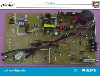

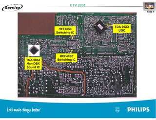

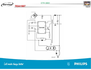
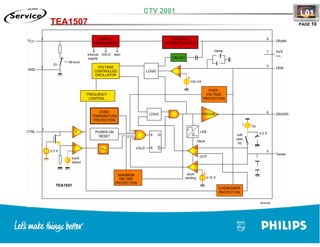


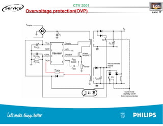
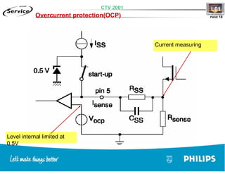


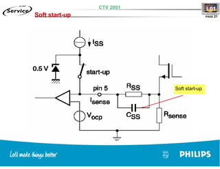
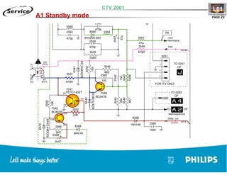
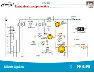
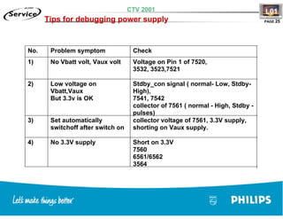

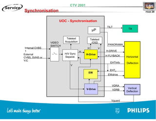
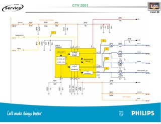
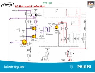
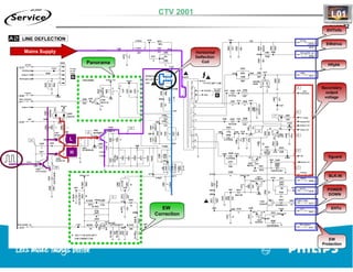
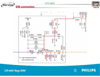
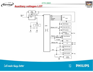
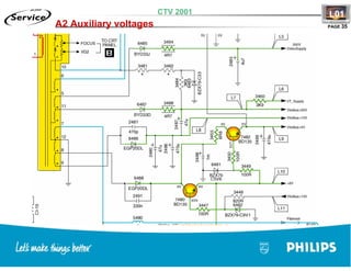
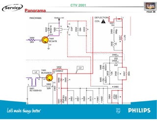
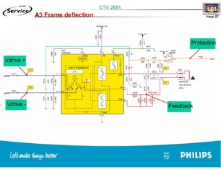
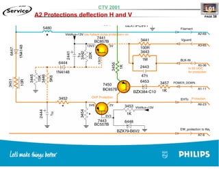


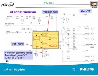


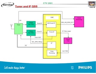
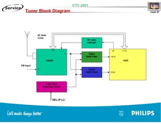
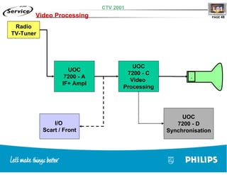
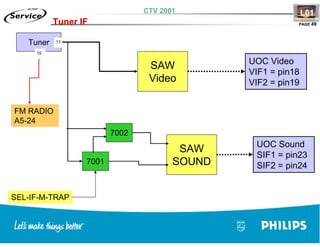

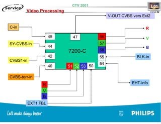
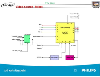


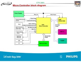


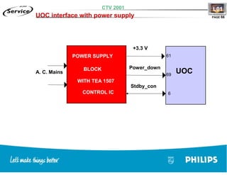
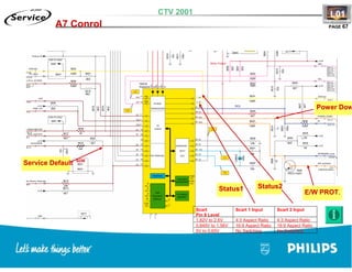
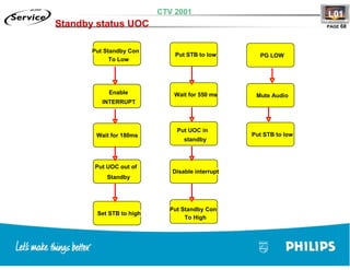

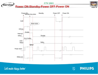


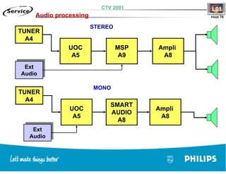
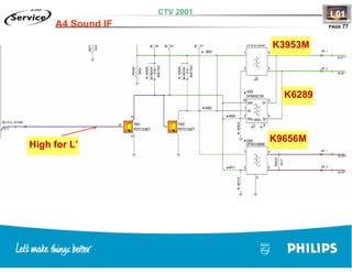
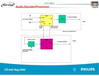


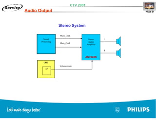


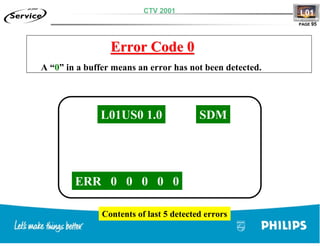
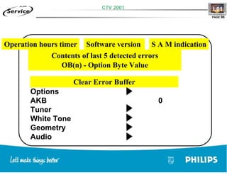


The document provides technical specifications and diagrams for a CTV 2001 color television. It includes a list of integrated circuits and components used in the lot, power supply, and deflection circuitry. Diagrams show the signal flow and components involved in synchronization, horizontal and vertical deflection, and various protection mechanisms. Troubleshooting tips are provided for issues related to startup, auxiliary voltage levels, and deflection problems.