This document provides an overview of an 11kV electrical system, including:
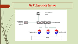
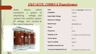
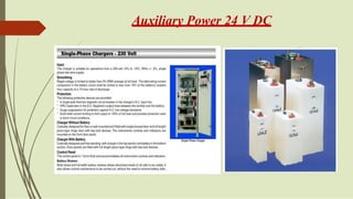
1) The main components of an 11kV electrical system including switchgear, distribution transformers, cables, and auxiliary power supply.
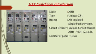
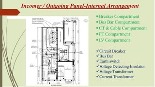
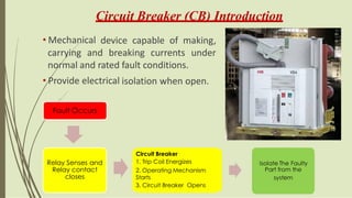
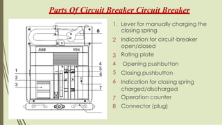
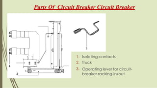
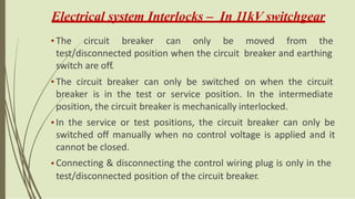
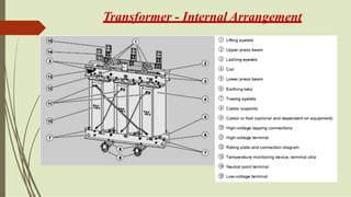
2) Details on the internal arrangement and functioning of 11kV switchgear, circuit breakers, and protection relays.
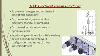
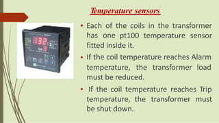
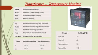
3) Explanations of temperature monitoring systems, interlocking mechanisms, and the roles of various components in protecting the electrical system.


![Transformer Repair Workshop Report [EEE]](https://cdn.slidesharecdn.com/ss_thumbnails/transformerrepairworkshopeee-140621072318-phpapp01-thumbnail.jpg?width=640&height=640&fit=bounds)