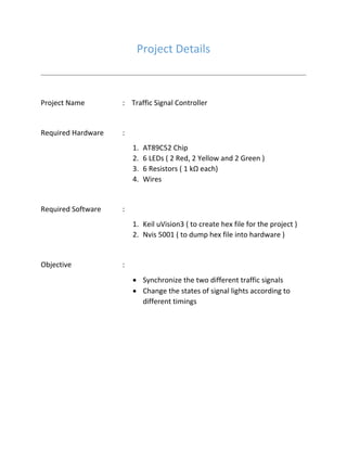
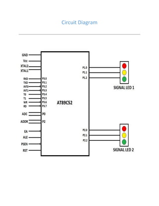
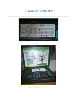
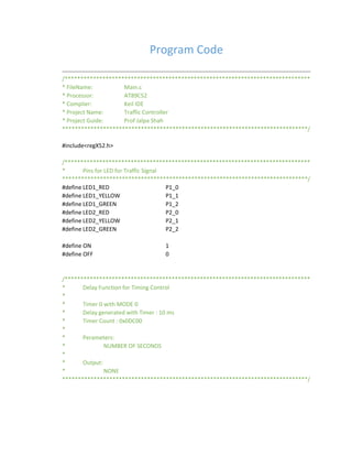
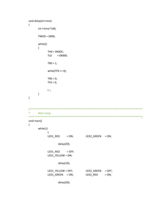
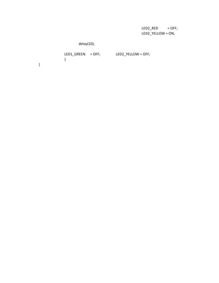
TRAFFIC SIGNAL CONTROLLER USING
AT89C52 MICROCONTROLLER
Microcontroller and its Applications
Guide Faculty : Prof Jalpa Shah
Vivek Patel ( 11BCE073 ), Yamini Rathod ( 11BCE078 )
11bce073@nirmauni.ac.in 11bce078@nirmauni.ac.in
Institute of Technology,
Nirma University
Project Details
Project Name : Traffic Signal Controller
Required Hardware :
1. AT89C52 Chip
2. 6 LEDs ( 2 Red, 2 Yellow and 2 Green )
3. 6 Resistors ( 1 kΩ each)
4. Wires
Required Software :
1. Keil uVision3 ( to create hex file for the project )
2. Nvis 5001 ( to dump hex file into hardware )
Objective :
 Synchronize the two different traffic signals
 Change the states of signal lights according to
different timings
Circuit Diagram
Hardware Implementation
Figure 1. Bread Board Signal LEDs Connection Diagram
Figure 2. Project Setup Connection Diagram
Project Description
 The project is based on the synchronization of two traffic signal using
AT89C52 Microcontroller.
 Here, there are two traffic control signals. They will change their states of
signal lights according to the different timings.
Figure 3. Nvis 5001 Circuit Connection Diagram with AT89052
 Assuming that there are two controls P1 and P2. P1 and P2 are synchronize
using the same timer. When one side signal port is on it will starts timer. Two
traffic controls are synchronize for every 30 seconds.
 When one control starts its working, it will starts timer and display red light
till timer reaches to 20 seconds. From 20 to 30 seconds it will display yellow
light. At the same time another control will display green light.
 When first control P1 reaches to timer value 30 seconds, it will stop timer. At
the same time second control P2 will starts timer. It will follow the same
procedure. The two controls work in the synchronous manner.
Program Code
/******************************************************************************
* FileName: Main.c
* Processor: AT89C52
* Complier: Keil IDE
* Project Name: Traffic Controller
* Project Guide: Prof Jalpa Shah
******************************************************************************/
#include<regX52.h>
/******************************************************************************
* Pins for LED for Traffic Signal
******************************************************************************/
#define LED1_RED P1_0
#define LED1_YELLOW P1_1
#define LED1_GREEN P1_2
#define LED2_RED P2_0
#define LED2_YELLOW P2_1
#define LED2_GREEN P2_2
#define ON 1
#define OFF 0
/******************************************************************************
* Delay Function for Timing Control
*
* Timer 0 with MODE 0
* Delay generated with Timer : 10 ms
* Timer Count : 0x0DC00
*
* Perameters:
* NUMBER OF SECONDS
*
* Output:
* NONE
******************************************************************************/
void delay(int time)
{
int i=time*100;
TMOD = 0X00;
while(i)
{
TH0 = 0X0DC;
TL0 = 0X000;
TR0 = 1;
while(TF0 == 0);
TR0 = 0;
TF0 = 0;
i--;
}
}
/******************************************************************************
* Main Loop
******************************************************************************/
void main()
{
while(1)
{
LED1_RED = ON; LED2_GREEN = ON;
delay(20);
LED1_RED = OFF;
LED1_YELLOW = ON;
delay(10);
LED1_YELLOW = OFF; LED2_GREEN = OFF;
LED1_GREEN = ON; LED2_RED = ON;
delay(20);
LED2_RED = OFF;
LED2_YELLOW = ON;
delay(10);
LED1_GREEN = OFF; LED2_YELLOW = OFF;
}
}

Traffic signal controller using at89 c52 microcontroller

  • 1.
    TRAFFIC SIGNAL CONTROLLERUSING AT89C52 MICROCONTROLLER Microcontroller and its Applications Guide Faculty : Prof Jalpa Shah Vivek Patel ( 11BCE073 ), Yamini Rathod ( 11BCE078 ) 11bce073@nirmauni.ac.in 11bce078@nirmauni.ac.in Institute of Technology, Nirma University
  • 2.
    Project Details Project Name: Traffic Signal Controller Required Hardware : 1. AT89C52 Chip 2. 6 LEDs ( 2 Red, 2 Yellow and 2 Green ) 3. 6 Resistors ( 1 kΩ each) 4. Wires Required Software : 1. Keil uVision3 ( to create hex file for the project ) 2. Nvis 5001 ( to dump hex file into hardware ) Objective :  Synchronize the two different traffic signals  Change the states of signal lights according to different timings
  • 3.
  • 4.
    Hardware Implementation Figure 1.Bread Board Signal LEDs Connection Diagram Figure 2. Project Setup Connection Diagram
  • 5.
    Project Description  Theproject is based on the synchronization of two traffic signal using AT89C52 Microcontroller.  Here, there are two traffic control signals. They will change their states of signal lights according to the different timings. Figure 3. Nvis 5001 Circuit Connection Diagram with AT89052  Assuming that there are two controls P1 and P2. P1 and P2 are synchronize using the same timer. When one side signal port is on it will starts timer. Two traffic controls are synchronize for every 30 seconds.  When one control starts its working, it will starts timer and display red light till timer reaches to 20 seconds. From 20 to 30 seconds it will display yellow light. At the same time another control will display green light.  When first control P1 reaches to timer value 30 seconds, it will stop timer. At the same time second control P2 will starts timer. It will follow the same procedure. The two controls work in the synchronous manner.
  • 6.
    Program Code /****************************************************************************** * FileName:Main.c * Processor: AT89C52 * Complier: Keil IDE * Project Name: Traffic Controller * Project Guide: Prof Jalpa Shah ******************************************************************************/ #include<regX52.h> /****************************************************************************** * Pins for LED for Traffic Signal ******************************************************************************/ #define LED1_RED P1_0 #define LED1_YELLOW P1_1 #define LED1_GREEN P1_2 #define LED2_RED P2_0 #define LED2_YELLOW P2_1 #define LED2_GREEN P2_2 #define ON 1 #define OFF 0 /****************************************************************************** * Delay Function for Timing Control * * Timer 0 with MODE 0 * Delay generated with Timer : 10 ms * Timer Count : 0x0DC00 * * Perameters: * NUMBER OF SECONDS * * Output: * NONE ******************************************************************************/
  • 7.
    void delay(int time) { inti=time*100; TMOD = 0X00; while(i) { TH0 = 0X0DC; TL0 = 0X000; TR0 = 1; while(TF0 == 0); TR0 = 0; TF0 = 0; i--; } } /****************************************************************************** * Main Loop ******************************************************************************/ void main() { while(1) { LED1_RED = ON; LED2_GREEN = ON; delay(20); LED1_RED = OFF; LED1_YELLOW = ON; delay(10); LED1_YELLOW = OFF; LED2_GREEN = OFF; LED1_GREEN = ON; LED2_RED = ON; delay(20);
  • 8.
    LED2_RED = OFF; LED2_YELLOW= ON; delay(10); LED1_GREEN = OFF; LED2_YELLOW = OFF; } }