Downloaded 44 times


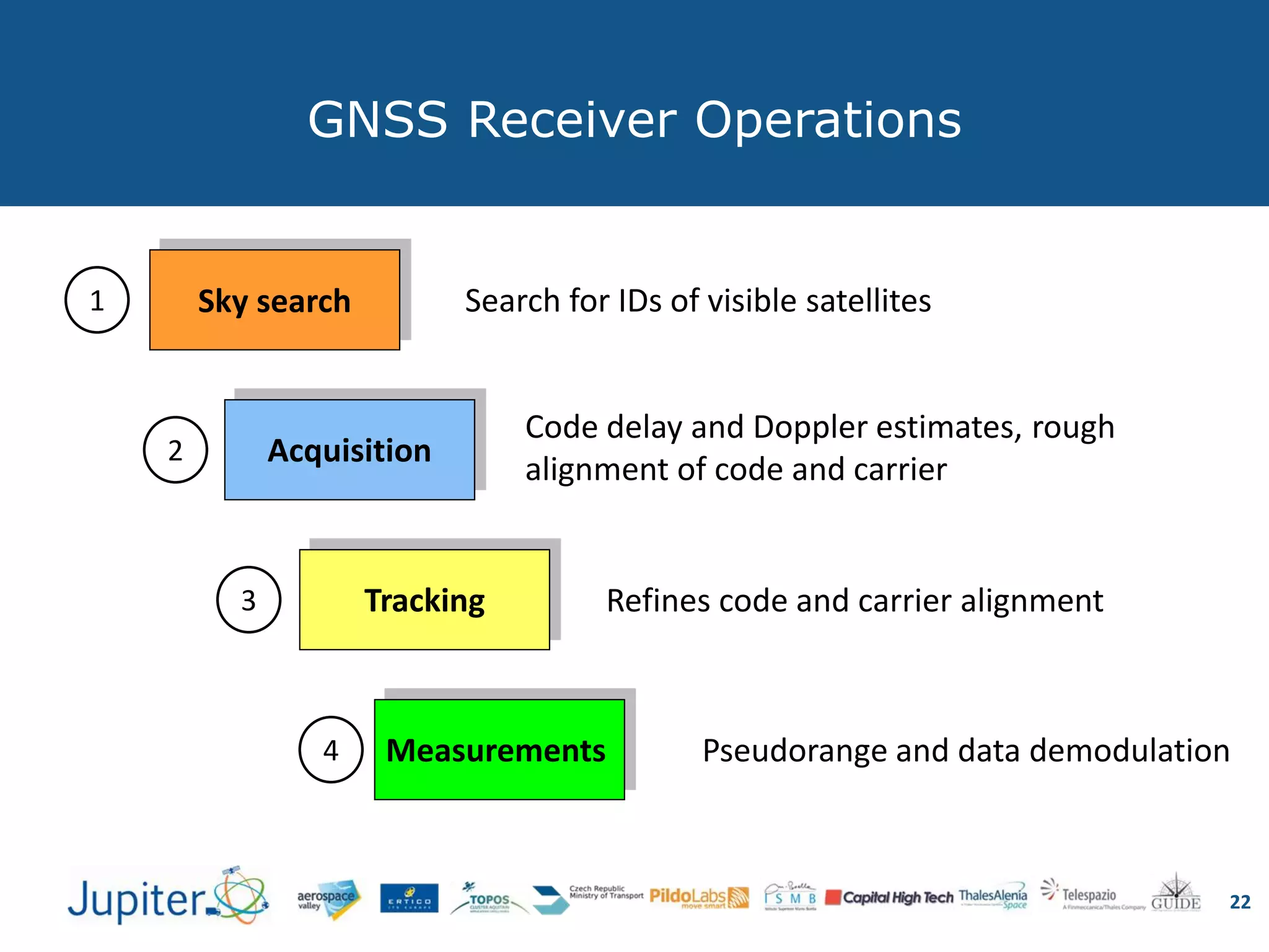

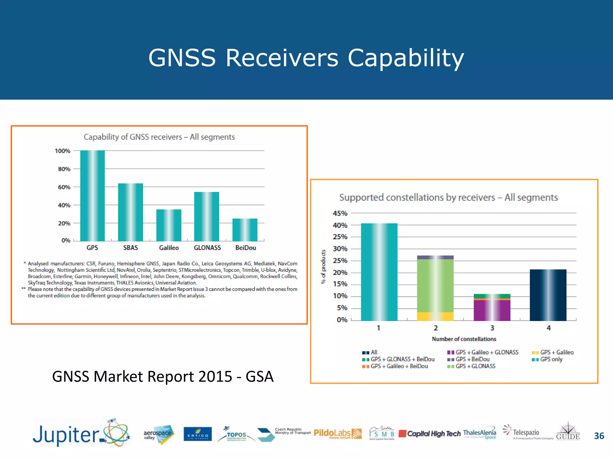
![Description Device Price [€]
Handheld receivers for hikers and sailors. Small
size with latitude-longitude displays and maps. 100 - 600
Integrated GPS in mobile phones. Low cost and
single frequency. 50-600
Maritime navigators. Fixed mount, large
screens with electronics chart 100-3000
In-car navigation systems. Detailed street
maps and turn-by-turn directions. These
systems can be also handheld (e.g. PDA)
100-2000
Receivers Classes
25
Price differences are due to reason independent from the embedded GNSS chip](https://image.slidesharecdn.com/jupiterwebinarfeb20161-160229140047/75/Towards-Autonomous-Driving-on-road-the-E-GNSS-contribution-25-2048.jpg)
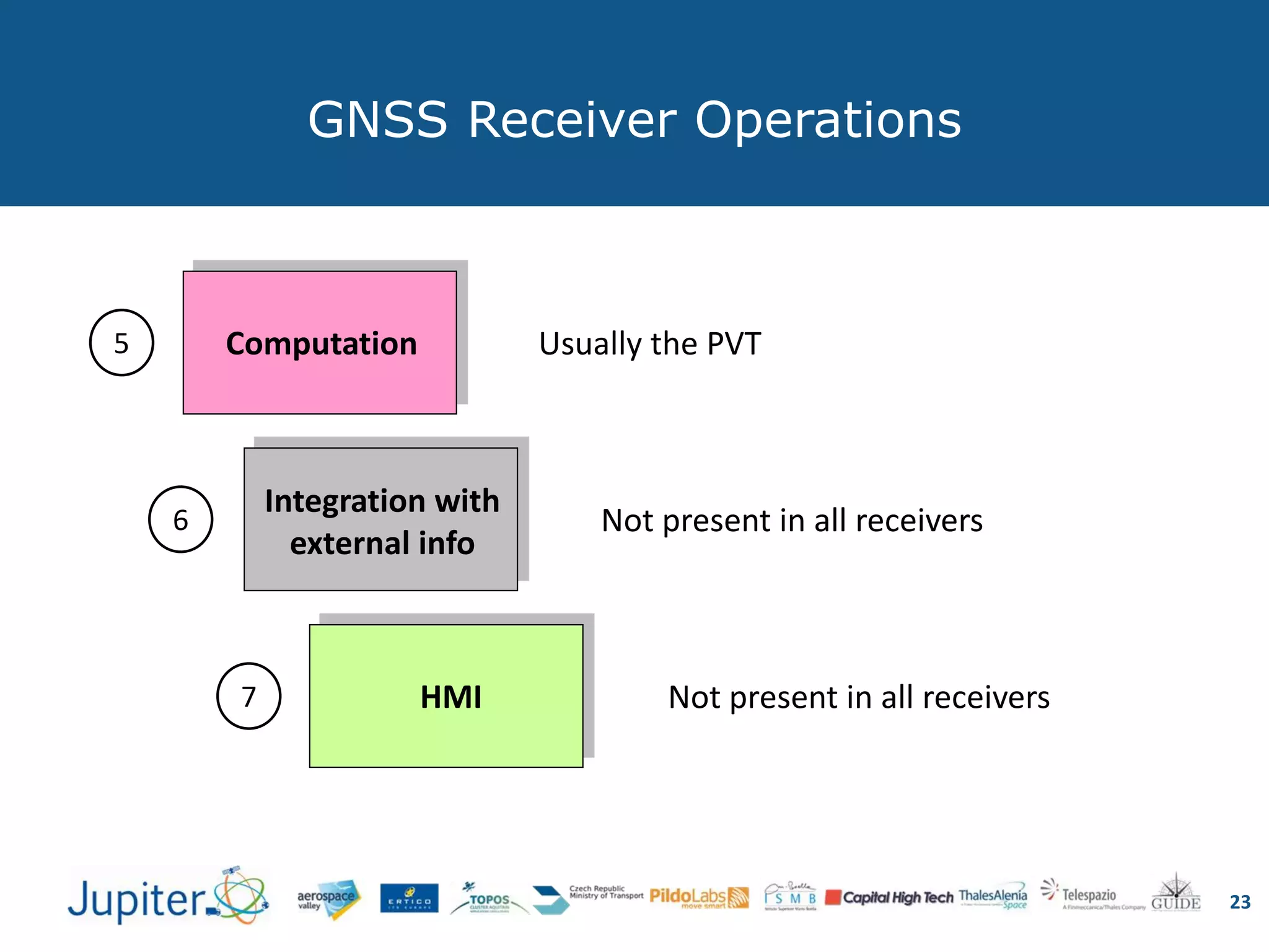
![Description Approx. Price [€]
Aviation receivers. FAA in US and EASA
in Europe certified, panel mounted with
maps.
INTEGRITY REQUIRED !
>3000
Survey and mapping professional
receivers. Multi-frequency and
differential GPS, centimeter accuracy
1500 – 30000
Receivers Classes
26
Price differences are due to reason independent from the embedded GNSS chip](https://image.slidesharecdn.com/jupiterwebinarfeb20161-160229140047/75/Towards-Autonomous-Driving-on-road-the-E-GNSS-contribution-26-2048.jpg)
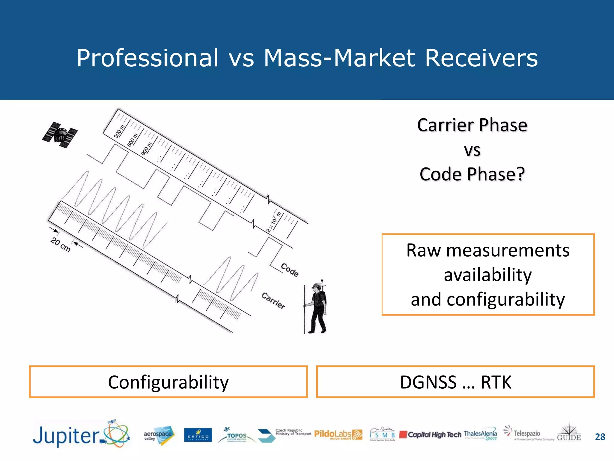
![Description Approx. Price [€]
Plug-in modules.
Integrated receivers and antenna.
Employed in tracking systems
30 – 700
OEM boards.
Employed for integration in other
complex systems.
100 – 5000
Chip sets.
Employed for integration, but all the
circuitry is needed
1 – 30
GNSS Modules
27](https://image.slidesharecdn.com/jupiterwebinarfeb20161-160229140047/75/Towards-Autonomous-Driving-on-road-the-E-GNSS-contribution-27-2048.jpg)


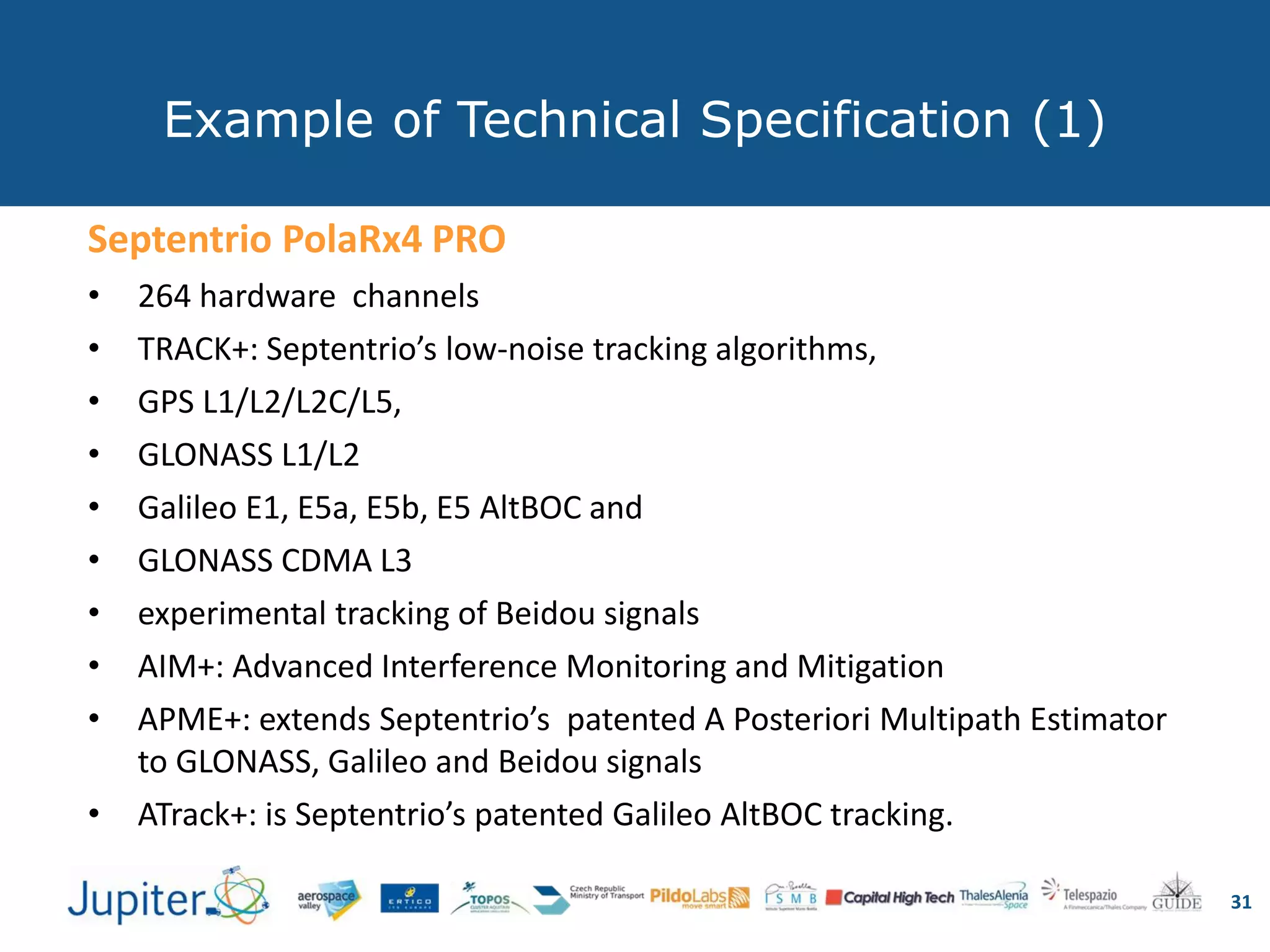


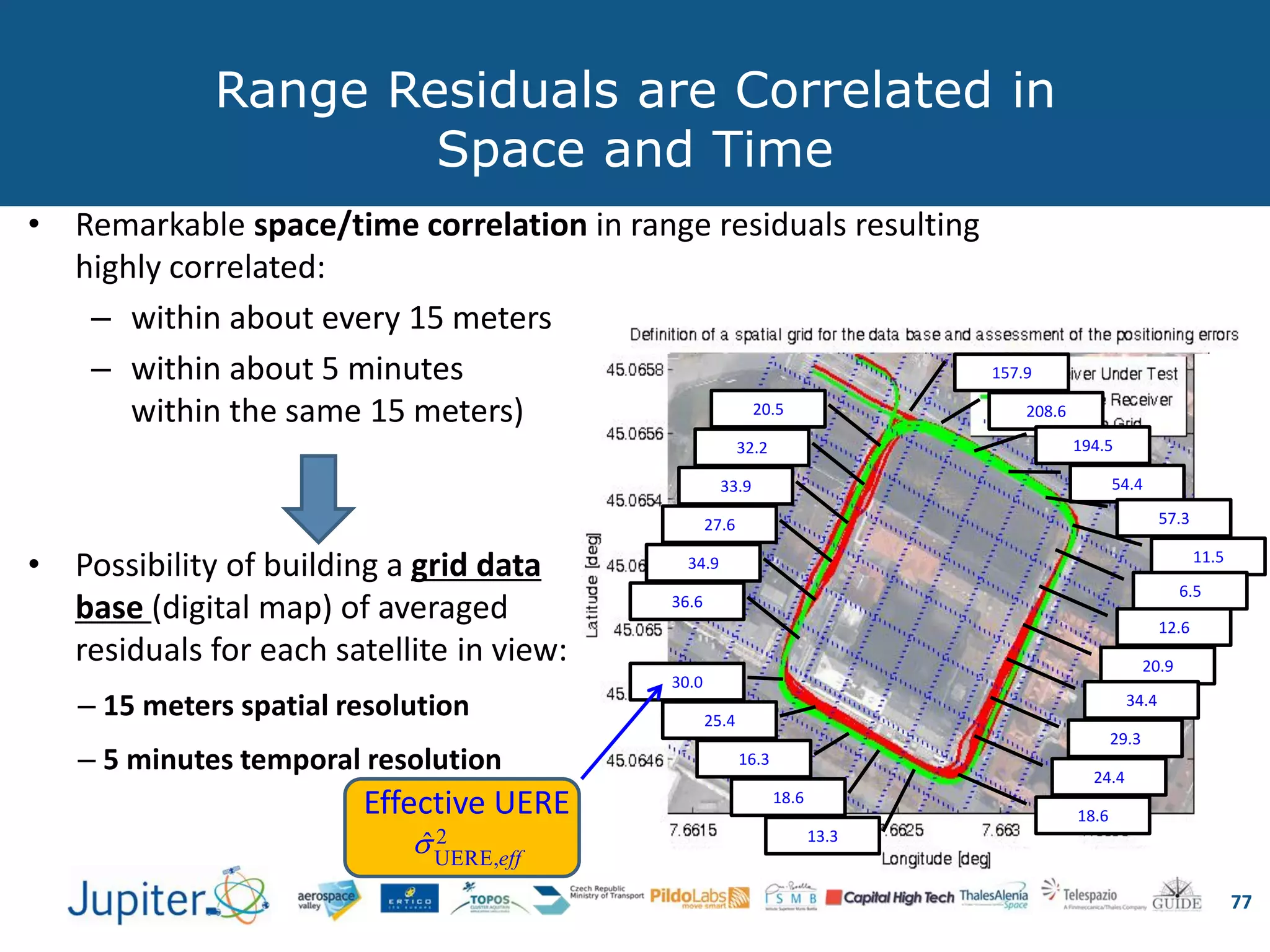
![Range residuals are repeatable
76
• Repeatable degradations of range residual measurements
– Along the same path
– Along several days
– Due to the periodicity of the GNSS satellite geometry
11:42:00 11:43:00 11:44:00 11:45:00 11:46:00 11:47:00 11:48:00 11:49:00 11:50:00 11:51:00 11:52:00 11:53:00 11:54:00
-50
-40
-30
-20
-10
0
10
UTC time
Rangeresiduals[m]
Range residuals for SVs used in navigation vs UTC time
PRN 05
PRN 07
PRN 08
PRN 10
PRN 15
PRN 21
PRN 24
PRN 28
PRN 09
PRN 26
30
210
60
240
90270
120
300
150
330
180
0
15
30
45
60
75
90
5
8
9
15
26
28
7
10
Skyplot (satellites used in PVT) at UTC time 11:42:00
Two consecutive passes
in the same position
(1 minute delay)](https://image.slidesharecdn.com/jupiterwebinarfeb20161-160229140047/75/Towards-Autonomous-Driving-on-road-the-E-GNSS-contribution-74-2048.jpg)


The document discusses the role of Global Navigation Satellite Systems (GNSS) in autonomous driving, outlining the technologies involved such as vehicle dynamics, perception, and navigation. It highlights how GNSS facilitates routing, navigation, and situational awareness for vehicles, while also addressing receiver operations, performance, and the impact of various errors. Additionally, it covers the European GNSS systems including EGNOS and Galileo, emphasizing their applications and improvements in accuracy and integrity for safety-critical services.


