Global Navigation SatelliteSystem
(GNSS)
College of Engineering
Karachi Institute of Economics and Technology
Instructor : Dr Shahid Baqar
Navigation, Guidance and Control
2.
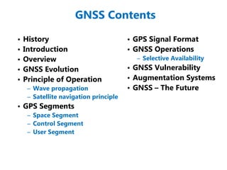
GNSS Contents
• History
•Introduction
• Overview
• GNSS Evolution
• Principle of Operation
– Wave propagation
– Satellite navigation principle
• GPS Segments
– Space Segment
– Control Segment
– User Segment
• GPS Signal Format
• GNSS Operations
– Selective Availability
• GNSS Vulnerability
• Augmentation Systems
• GNSS – The Future
3.
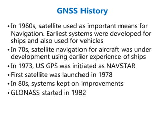
GNSS History
• In1960s, satellite used as important means for
Navigation. Earliest systems were developed for
ships and also used for vehicles
• In 70s, satellite navigation for aircraft was under
development using earlier experience of ships
• In 1973, US GPS was initiated as NAVSTAR
• First satellite was launched in 1978
• In 80s, systems kept on improvements
• GLONASS started in 1982
4.
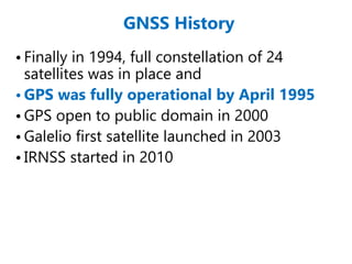
GNSS History
• Finallyin 1994, full constellation of 24
satellites was in place and
• GPS was fully operational by April 1995
• GPS open to public domain in 2000
• Galelio first satellite launched in 2003
• IRNSS started in 2010
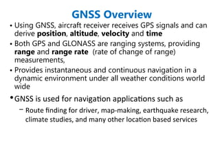
GNSS Overview
• UsingGNSS, aircraft receiver receives GPS signals and can
derive position, altitude, velocity and time
• Both GPS and GLONASS are ranging systems, providing
range and range rate (rate of change of range)
measurements,
• Provides instantaneous and continuous navigation in a
dynamic environment under all weather conditions world
wide
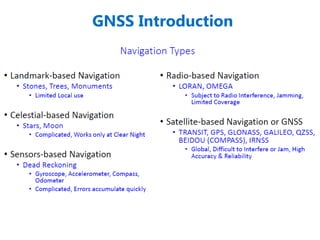
•GNSS is used for navigation applications such as
– Route finding for driver, map-making, earthquake research,
climate studies, and many other location based services
7.
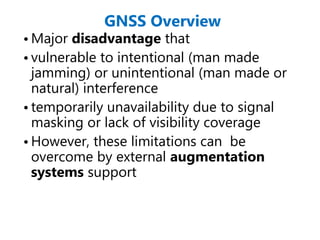
GNSS Overview
• Majordisadvantage that
• vulnerable to intentional (man made
jamming) or unintentional (man made or
natural) interference
• temporarily unavailability due to signal
masking or lack of visibility coverage
• However, these limitations can be
overcome by external augmentation
systems support
9.
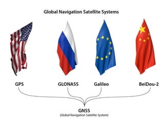
Global Navigation SatelliteSystem
(GNSS)
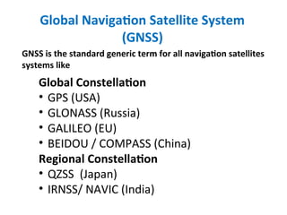
GNSS is the standard generic term for all navigation satellites
systems like
Global Constellation
• GPS (USA)
• GLONASS (Russia)
• GALILEO (EU)
• BEIDOU / COMPASS (China)
Regional Constellation
• QZSS (Japan)
• IRNSS/ NAVIC (India)
10.
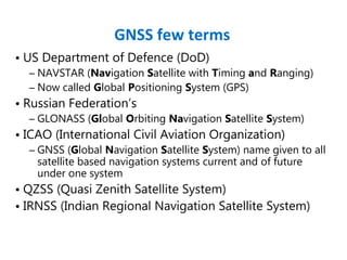
• US Departmentof Defence (DoD)
– NAVSTAR (Navigation Satellite with Timing and Ranging)
– Now called Global Positioning System (GPS)
• Russian Federation’s
– GLONASS (Global Orbiting Navigation Satellite System)
• ICAO (International Civil Aviation Organization)
– GNSS (Global Navigation Satellite System) name given to all
satellite based navigation systems current and of future
under one system
• QZSS (Quasi Zenith Satellite System)
• IRNSS (Indian Regional Navigation Satellite System)
GNSS few terms
11.
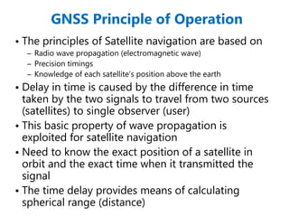
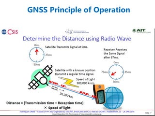
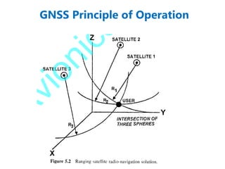
GNSS Principle ofOperation
• The principles of Satellite navigation are based on
– Radio wave propagation (electromagnetic wave)
– Precision timings
– Knowledge of each satellite’s position above the earth
• Delay in time is caused by the difference in time
taken by the two signals to travel from two sources
(satellites) to single observer (user)
• This basic property of wave propagation is
exploited for satellite navigation
• Need to know the exact position of a satellite in
orbit and the exact time when it transmitted the
signal
• The time delay provides means of calculating
spherical range (distance)
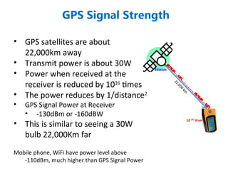
GPS Signal Strength
•GPS satellites are about
22,000km away
• Transmit power is about 30W
• Power when received at the
receiver is reduced by 1016
times
• The power reduces by 1/distance2
• GPS Signal Power at Receiver
• -130dBm or -160dBW
• This is similar to seeing a 30W
bulb 22,000Km far
Mobile phone, WiFi have power level above
-110dBm, much higher than GPS Signal Power
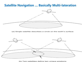
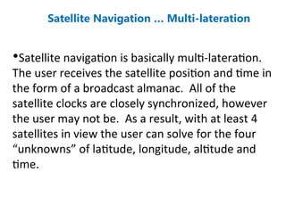
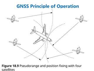
Satellite Navigation …Multi-lateration
•Satellite navigation is basically multi-lateration.
The user receives the satellite position and time in
the form of a broadcast almanac. All of the
satellite clocks are closely synchronized, however
the user may not be. As a result, with at least 4
satellites in view the user can solve for the four
“unknowns” of latitude, longitude, altitude and
time.
16.
a
b
c
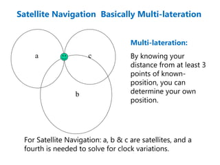
Satellite Navigation BasicallyMulti-lateration
Multi-lateration:
By knowing your
distance from at least 3
points of known-
position, you can
determine your own
position.
For Satellite Navigation: a, b & c are satellites, and a
fourth is needed to solve for clock variations.
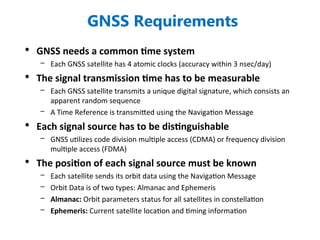
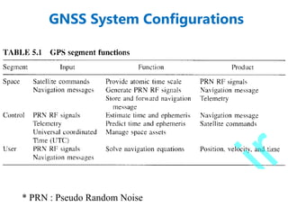
GNSS Requirements
• GNSSneeds a common time system
– Each GNSS satellite has 4 atomic clocks (accuracy within 3 nsec/day)
• The signal transmission time has to be measurable
– Each GNSS satellite transmits a unique digital signature, which consists an
apparent random sequence
– A Time Reference is transmitted using the Navigation Message
• Each signal source has to be distinguishable
– GNSS utilizes code division multiple access (CDMA) or frequency division
multiple access (FDMA)
• The position of each signal source must be known
– Each satellite sends its orbit data using the Navigation Message
– Orbit Data is of two types: Almanac and Ephemeris
– Almanac: Orbit parameters status for all satellites in constellation
– Ephemeris: Current satellite location and timing information
21.
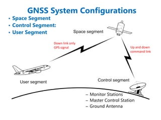
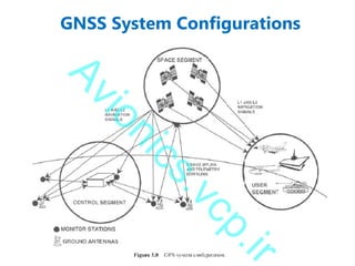
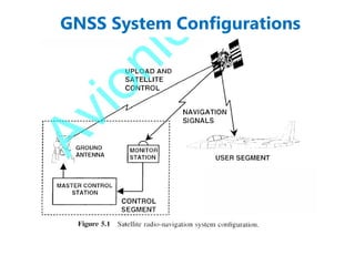
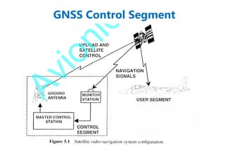
GNSS System Configurations
Upand down
command link
Down link only
GPS signal
– Monitor Stations
– Master Control Station
– Ground Antenna
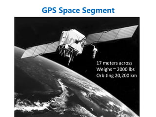
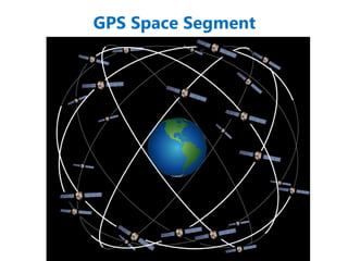
• Space Segment
• Control Segment:
• User Segment
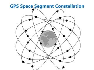
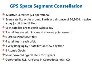
GPS Space SegmentConstellation
32 active Satellites (24 operational)
Every satellite orbits around Earth at a distance of 20,200 km twice
a day (orbit time 12 Hour
Each satellite orbits earth twice a day
5 satellites are with in view at any one point on earth
6 Orbital Planes (55o
tilt)
4 satellites in each orbit
1 Way Ranging by 5 satellites in view any time
4 Atomic Clocks
Solar powered typical life 5 to 10 years
Operated by U.S. Air Force in Colorado Springs, CO
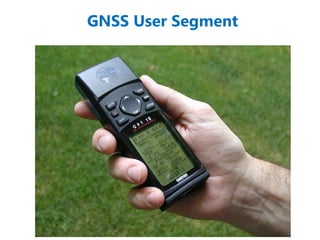
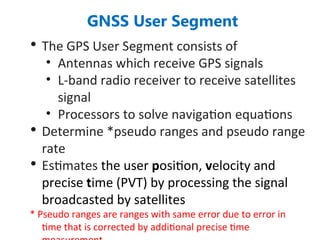
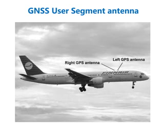
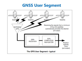
GNSS User Segment
•The GPS User Segment consists of
• Antennas which receive GPS signals
• L-band radio receiver to receive satellites
signal
• Processors to solve navigation equations
• Determine *pseudo ranges and pseudo range
rate
• Estimates the user position, velocity and
precise time (PVT) by processing the signal
broadcasted by satellites
* Pseudo ranges are ranges with same error due to error in
time that is corrected by additional precise time
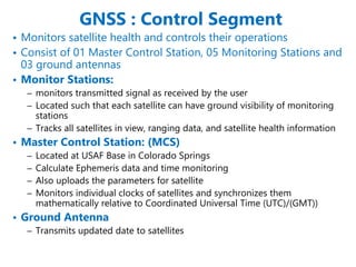
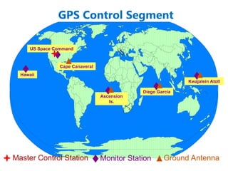
GNSS : ControlSegment
• Monitors satellite health and controls their operations
• Consist of 01 Master Control Station, 05 Monitoring Stations and
03 ground antennas
• Monitor Stations:
– monitors transmitted signal as received by the user
– Located such that each satellite can have ground visibility of monitoring
stations
– Tracks all satellites in view, ranging data, and satellite health information
• Master Control Station: (MCS)
– Located at USAF Base in Colorado Springs
– Calculate Ephemeris data and time monitoring
– Also uploads the parameters for satellite
– Monitors individual clocks of satellites and synchronizes them
mathematically relative to Coordinated Universal Time (UTC)/(GMT))
• Ground Antenna
– Transmits updated date to satellites
37.
GPS Control Segment
KwajaleinAtoll
US Space Command
Hawaii
Ascension
Is.
Diego Garcia
Cape Canaveral
Ground Antenna
Master Control Station Monitor Station
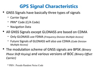
GPS Signal Characteristics
•GNSS Signals have basically three types of signals
– Carrier Signal
– PRN* Code (C/A Code)
– Navigation Data
• All GNSS Signals except GLONASS are based on CDMA
– Only GLONASS use FDMA (Frequency Division Multiple Access)
– Future Signals of GLONASS will also use CDMA (Code Division
Multiple Access)
• The modulation scheme of GNSS signals are BPSK (Binary
Phase Shift Keying) and various versions of BOC (Binary Offset
Carrier)
* PRN : Pseudo Random Noise Code
40.
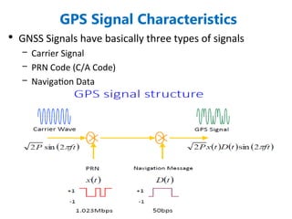
GPS Signal Characteristics
•GNSS Signals have basically three types of signals
– Carrier Signal
– PRN Code (C/A Code)
– Navigation Data
41.
GPS Signal Characteristics
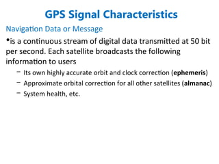
NavigationData or Message
•is a continuous stream of digital data transmitted at 50 bit
per second. Each satellite broadcasts the following
information to users
– Its own highly accurate orbit and clock correction (ephemeris)
– Approximate orbital correction for all other satellites (almanac)
– System health, etc.
42.
GPS Signal Characteristics
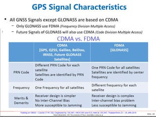
•All GNSS Signals except GLONASS are based on CDMA
– Only GLONASS use FDMA (Frequency Division Multiple Access)
– Future Signals of GLONASS will also use CDMA (Code Division Multiple Access)
43.
GPS Signal Characteristics
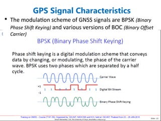
•The modulation scheme of GNSS signals are BPSK (Binary
Phase Shift Keying) and various versions of BOC (Binary Offset
Carrier)
44.
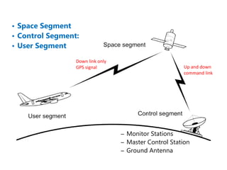
Up and down
commandlink
Down link only
GPS signal
– Monitor Stations
– Master Control Station
– Ground Antenna
• Space Segment
• Control Segment:
• User Segment
45.
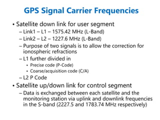
GPS Signal CarrierFrequencies
• Satellite down link for user segment
– Link1 – L1 – 1575.42 MHz (L-Band)
– Link2 – L2 – 1227.6 MHz (L-Band)
– Purpose of two signals is to allow the correction for
ionospheric refractions
– L1 further divided in
• Precise code (P-Code)
• Coarse/acquisition code (C/A)
– L2 P Code
• Satellite up/down link for control segment
– Data is exchanged between each satellite and the
monitoring station via uplink and downlink frequencies
in the S-band (2227.5 and 1783.74 MHz respectively)
50.
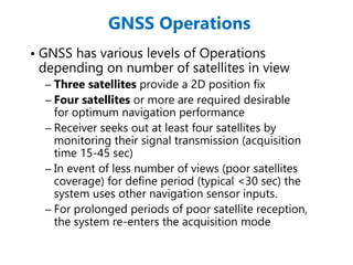
GNSS Operations
• GNSShas various levels of Operations
depending on number of satellites in view
– Three satellites provide a 2D position fix
– Four satellites or more are required desirable
for optimum navigation performance
– Receiver seeks out at least four satellites by
monitoring their signal transmission (acquisition
time 15-45 sec)
– In event of less number of views (poor satellites
coverage) for define period (typical <30 sec) the
system uses other navigation sensor inputs.
– For prolonged periods of poor satellite reception,
the system re-enters the acquisition mode
51.
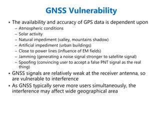
GNSS Vulnerability
• Theavailability and accuracy of GPS data is dependent upon
– Atmospheric conditions
– Solar activity
– Natural impediment (valley, mountains shadow)
– Artificial impediment (urban buildings)
– Close to power lines (influence of EM fields)
– Jamming (generating a noise signal stronger to satellite signal)
– Spoofing (convincing user to accept a false PNT signal as the real
thing)
• GNSS signals are relatively weak at the receiver antenna, so
are vulnerable to interference
• As GNSS typically serve more users simultaneously, the
interference may affect wide geographical area
52.
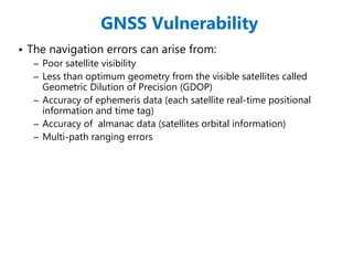
GNSS Vulnerability
• Thenavigation errors can arise from:
– Poor satellite visibility
– Less than optimum geometry from the visible satellites called
Geometric Dilution of Precision (GDOP)
– Accuracy of ephemeris data (each satellite real-time positional
information and time tag)
– Accuracy of almanac data (satellites orbital information)
– Multi-path ranging errors
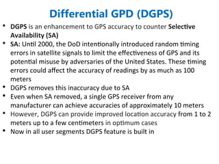
• DGPS isan enhancement to GPS accuracy to counter Selective
Availability (SA)
• SA: Until 2000, the DoD intentionally introduced random timing
errors in satellite signals to limit the effectiveness of GPS and its
potential misuse by adversaries of the United States. These timing
errors could affect the accuracy of readings by as much as 100
meters
• DGPS removes this inaccuracy due to SA
• Even when SA removed, a single GPS receiver from any
manufacturer can achieve accuracies of approximately 10 meters
• However, DGPS can provide improved location accuracy from 1 to 2
meters up to a few centimeters in optimum cases
• Now in all user segments DGPS feature is built in
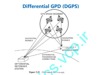
Differential GPD (DGPS)
56.
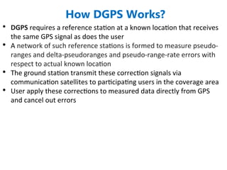
• DGPS requiresa reference station at a known location that receives
the same GPS signal as does the user
• A network of such reference stations is formed to measure pseudo-
ranges and delta-pseudoranges and pseudo-range-rate errors with
respect to actual known location
• The ground station transmit these correction signals via
communication satellites to participating users in the coverage area
• User apply these corrections to measured data directly from GPS
and cancel out errors
How DGPS Works?
57.
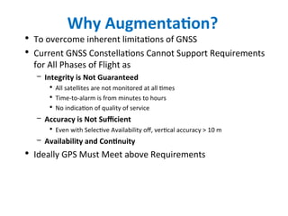
Why Augmentation?
• Toovercome inherent limitations of GNSS
• Current GNSS Constellations Cannot Support Requirements
for All Phases of Flight as
– Integrity is Not Guaranteed
• All satellites are not monitored at all times
• Time-to-alarm is from minutes to hours
• No indication of quality of service
– Accuracy is Not Sufficient
• Even with Selective Availability off, vertical accuracy > 10 m
– Availability and Continuity
• Ideally GPS Must Meet above Requirements
58.
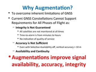
Why Augmentation?
• Toovercome inherent limitations of GNSS
• Current GNSS Constellations Cannot Support
Requirements for All Phases of Flight as:
– Integrity is Not Guaranteed
• All satellites are not monitored at all times
• Time-to-alarm is from minutes to hours
• No indication of quality of service
– Accuracy is Not Sufficient
• Even with Selective Availability off, vertical accuracy > 10 m
– Availability and Continuity
•Augmentations improve signal
availability, accuracy, integrity
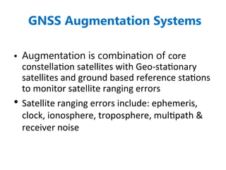
GNSS Augmentation Systems
•Augmentation is combination of core
constellation satellites with Geo-stationary
satellites and ground based reference stations
to monitor satellite ranging errors
• Satellite ranging errors include: ephemeris,
clock, ionosphere, troposphere, multipath &
receiver noise
61.
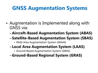
GNSS Augmentation Systems
•Augmentation is Implemented along with
GNSS via:
–Aircraft-Based Augmentation System (ABAS)
–Satellite-Based Augmentation System (SBAS)
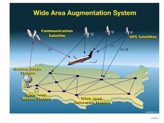
• Wide Area Augmentation System (WAAS)
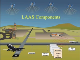
–Local Area Augmentation System (LAAS)
• Ground-Based Augmentation System (GBAS)
–Ground-Based Regional System (GRAS)
62.
Aircraft-Based Augmentation
System (ABAS)
ABASis the on-board avionics
implementation that processes GNSS
signals to achieve the accuracy and
integrity required to support en-route,
terminal, and non-precision approaches
(NPA) operations
63.
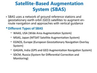
Satellite-Based Augmentation
System (SBAS)
•SBAS uses a network of ground reference stations and
geostationary earth orbit (GEO) satellites to augment en-
route navigation and approaches with vertical guidance
•Different Types of SBAS
– WAAS, USA (Wide Area Augmentation System)
– MSAS, Japan (MTSAT Satellite Augmentation System)
– EGNOS, Europe (European Geostationary Navigation Overlay
System)
– GAGAN, India (GPS and GEO Augmentation Navigation System)
– SDCM, Russia (System for Differential Correction and
Monitoring)
64.
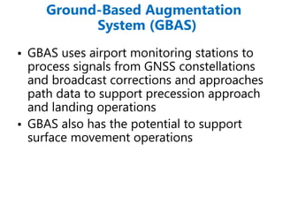
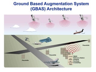
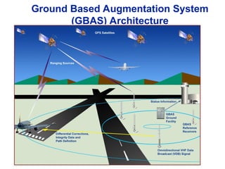
Ground-Based Augmentation
System (GBAS)
•GBAS uses airport monitoring stations to
process signals from GNSS constellations
and broadcast corrections and approaches
path data to support precession approach
and landing operations
• GBAS also has the potential to support
surface movement operations
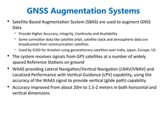
GNSS Augmentation Systems
•Satellite Based Augmentation System (SBAS) are used to augment GNSS
Data
– Provide Higher Accuracy, Integrity, Continuity and Availability
– Some correction data like satellite orbit, satellite clock and atmospheric data are
broadcasted from communication satellites
– Used by ICAO for Aviation using geostationary satellites over India, Japan, Europe, US
• The system receives signals from GPS satellites at a number of widely
spaced Reference Stations on ground
• WAAS providing Lateral Navigation/Vertical Navigation (LNAV/VNAV) and
Localized Performance with Vertical Guidance (LPV) capability, using the
accuracy of the WAAS signal to provide vertical (glide path) capability
• Accuracy improved from about 20m to 1.5-2 meters in both horizontal and
vertical dimensions
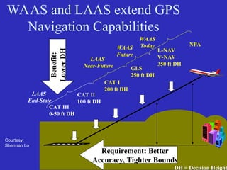
WAAS and LAASextend GPS
Navigation Capabilities
CAT I
200 ft DH
L-NAV
V-NAV
350 ft DH
NPA
CAT II
100 ft DH
CAT III
0-50 ft DH
GLS
250 ft DH
DH = Decision Height
Requirement: Better
Accuracy, Tighter Bounds
Benefit:
Lower
DH
Courtesy:
Sherman Lo
WAAS
Today
WAAS
Future
LAAS
Near-Future
LAAS
End-State
72.
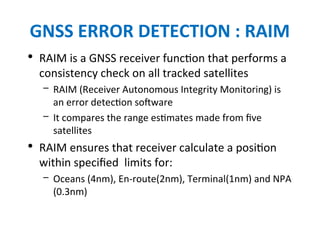
GNSS ERROR DETECTION: RAIM
• RAIM is a GNSS receiver function that performs a
consistency check on all tracked satellites
– RAIM (Receiver Autonomous Integrity Monitoring) is
an error detection software
– It compares the range estimates made from five
satellites
• RAIM ensures that receiver calculate a position
within specified limits for:
– Oceans (4nm), En-route(2nm), Terminal(1nm) and NPA
(0.3nm)
73.
Planned GNSS Modernization
•Addition of satellite constellations
– Galileo, additional GLONASS satellites
– Improves user availability
• Addition of civil signals
– Facilitates user ionospheric corrections
– Possible broadcast of integrity signal
• Increased power, improved coding
– Better resistance to interference
• Improvements in Augmentation Systems
74.
GNSS – TheFuture
• Rationalize the air traffic management through
increase use of GNSS
• Eventually replace ADF and VOR nav aids
• Automatic approach and landing with GNSS with
ILS/MLS as standby
• However, with increased dependency on GNSS,
the impact of any disruption is significant
• Thus conventional systems can not be totally
removed, rather further research is to be done in
these areas to bring some thing to replace GNSS
75.
References
• International CivilAviation Organization, Spectrum Seminar, Cairo, Egypt June 4-6, 2006
• GPS and GNSS Research at Stanford University http://scpnt.stanford.edu
• https://gps.stanford.edu/currentcontinuing-research/laas-gbas
• Dinesh Manandhar, Center for Spatial Information Science, The University of Tokyo
• Web site http://gps.faa.gov
• https://www.nasa.gov/feature/jpl/what-is-an-atomic-clock
76.
Videos or URLsto watch
• https://www.youtube.com/watch?v=6E_4jhFalXE (see at 23 minutes for GNSS)
• https://spaceplace.nasa.gov/spacecraft-graveyard/en/#:~:text=There%20is%20a
%20solution%E2%80%94spacecraft,human%20civilization%20you%20can
%20find.
•
Editor's Notes
#15 Satellite navigation is basically multilateration. The user receives the satellite position and time in the form of a broadcast almanac. All of the satellite clocks are closely synchronized, however the user may not be. As a result, with at least 4 satellites in view the user can solve for the four “unknowns” of latitude, longitude, altitude and time.
#16 Satellite navigation is basically multilateration. The user receives the satellite position and time in the form of a broadcast almanac. All of the satellite clocks are closely synchronized, however the user may not be. As a result, with at least 4 satellites in view the user can solve for the four “unknowns” of latitude, longitude, altitude and time.
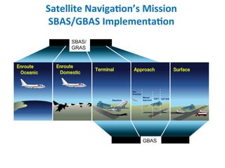
#68 GNSS by itself provides a global navigation and timing capability. With the addition of SBAS and/or GBAS, the benefits are increased.
SBAS: Enroute oceanic and domestic, terminal operations including departure guidance, and approach/missed approach through as low as CAT I.
GBAS: Precision terminal, approach and surface operations. CAT II/III goal.
#70 Example shows the United States version of SBAS, termed the Wide Area Augmentation System (WAAS). This system was commissioned July 10, 2003, and is currently providing Lateral Navigation/Vertical Navigation (LNAV/VNAV) and LPV capability, using the accuracy of the WAAS signal to provide vertical (glide path) capability.
The system receives signals from GPS satellites at a number of widely spaced Wide Area Reference Stations. Unlike aircraft, those stations receive both the GPS L1 civil signal, and the encrypted GPS L2 signal. The latter is used in a semi-codeless fashion to derive correction factors to compensate for bending of the radio-frequency signal as it goes through the Earth’s atmosphere. These corrections are transmitted via land line to the WAAS Wide Area Master Stations. Derived corrections are sent via geostationary satellites and downlinked on the GPS L1 frequency, providing both the enhanced accuracy/integrity information, and additional ranging sources.
Accuracy improved from about 20m to 1.5-2 meters in both horizontal and vertical dimensions.
Integrity data informs users of where GPS is unusable due to system or other errors. 6 second time-to-alarm supported.
Currently adding satellites to ensure redundant coverage over all CONUS and most of Alaska. Working with Canada and Mexico to further expand coverage.
For more information on WAAS see http://gps.faa.gov
#72 Focuses on service to a local area (20-30 mile radius).
Correction/integrity information broadcast over VHF frequency in the 108-117.975 MHz ARNS band.
Foreseen uses include CAT I/II/III landings and a positioning service to support RNAV operations in the terminal area.
#73 Focuses on service to a local area (20-30 mile radius).
Correction/integrity information broadcast over VHF frequency in the 108-117.975 MHz ARNS band.
Foreseen uses include CAT I/II/III landings and a positioning service to support RNAV operations in the terminal area.
#74 WAAS extends navigation capabilities of GPS.
Allows NPA but more importantly approaches with vertical guidance
These are generally lower pilot work load/less configuration changes
Lower landing minimums allows for operations in more adverse visibility conditions