Downloaded 256 times


![Arduino search
Buy | Download | Getting Started | Learning | Reference | Hardware | FAQ Blog » | Forum » | Playground »
Learning Examples | Foundations | Hacking | Links
Examples > Digital I/O
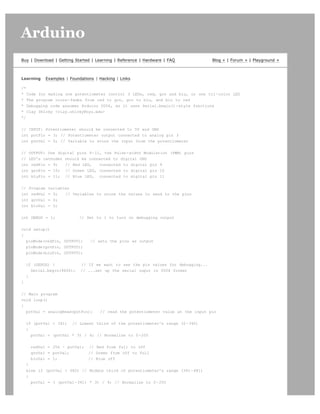
Loop
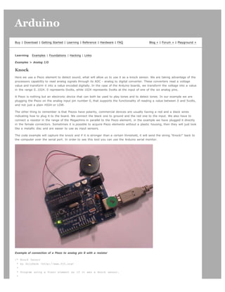
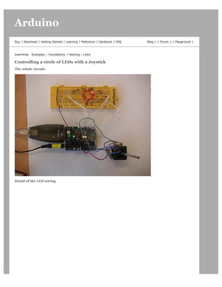
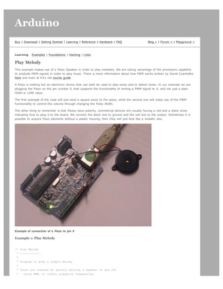
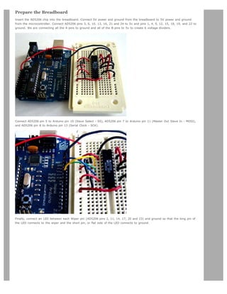
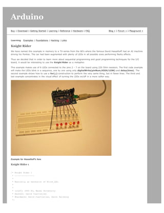
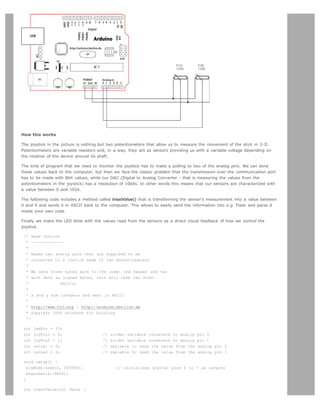
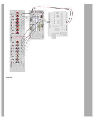
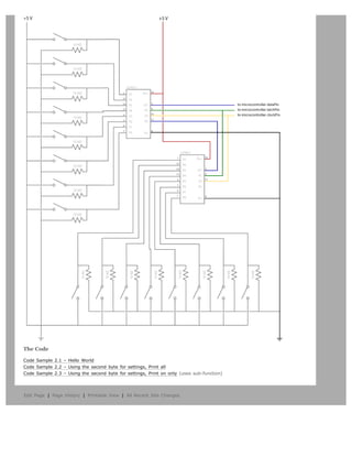
We also call this example "Knight Rider" in memory to a TV-series from the 80's where the famous David Hasselhoff had an
AI machine driving his Pontiac. The car had been augmented with plenty of LEDs in all possible sizes performing flashy
effects.
Thus we decided that in order to learn more about sequential programming and good programming techniques for the I/O
board, it would be interesting to use the Knight Rider as a metaphor.
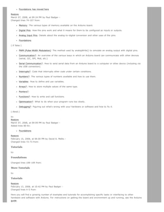
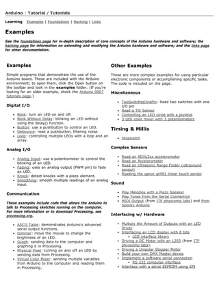
This example makes use of 6 LEDs connected to the pins 2 - 7 on the board using 220 Ohm resistors. The first code example
will make the LEDs blink in a sequence, one by one using only digitalWrite(pinNum,HIGH/LOW) and delay(time). The
second example shows how to use a for(;;) construction to perform the very same thing, but in fewer lines. The third and
last example concentrates in the visual effect of turning the LEDs on/off in a more softer way.
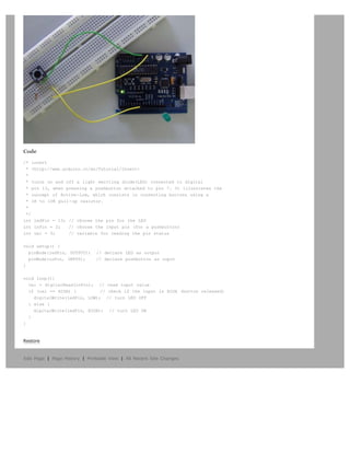
Circuit
Code
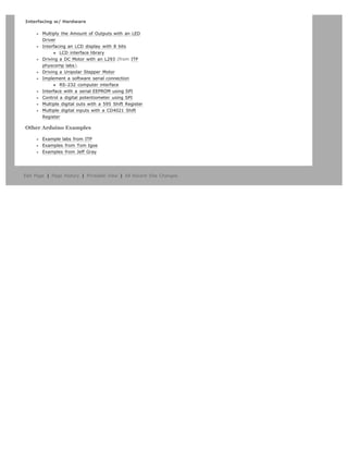
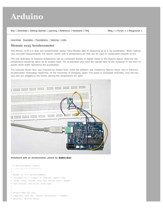
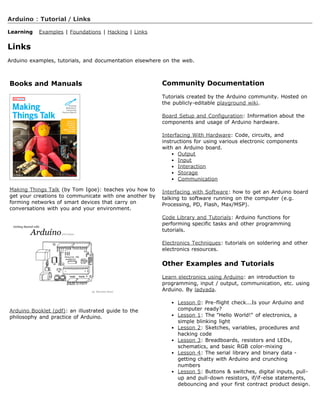
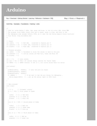
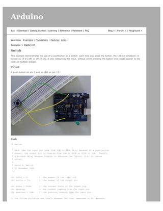
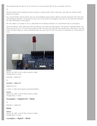
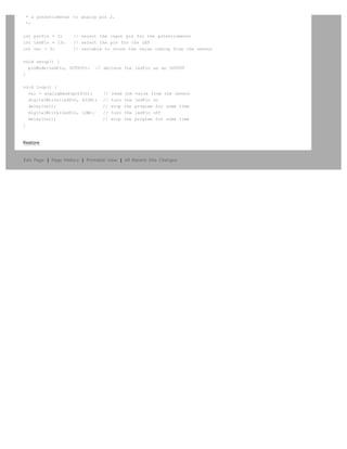
int timer = 100; // The higher the number, the slower the timing.
int pins[] = { 2, 3, 4, 5, 6, 7 }; // an array of pin numbers
int num_pins = 6; // the number of pins (i.e. the length of the array)
void setup()
{
int i;
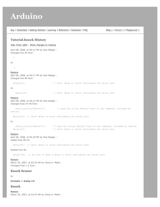
for (i = 0; i < num pins; i++) // the array elements are numbered from 0 to num pins - 1](https://image.slidesharecdn.com/arduino-learning-111105084504-phpapp01/85/Arduino-learning-15-320.jpg)
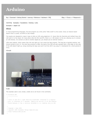
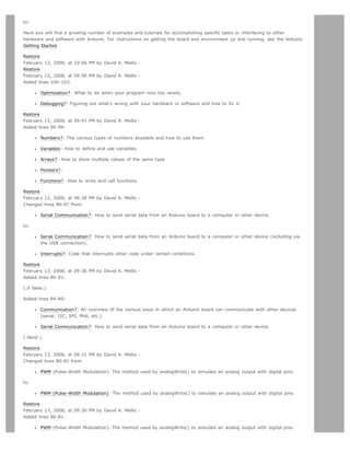
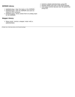
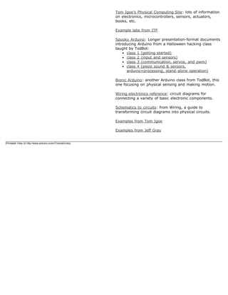
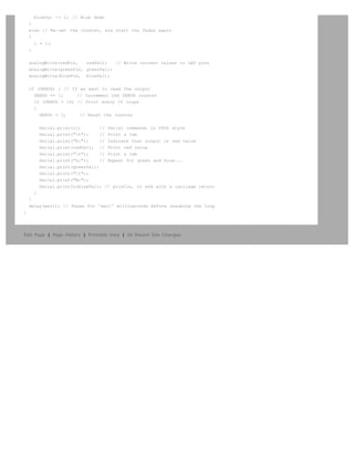
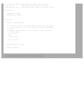
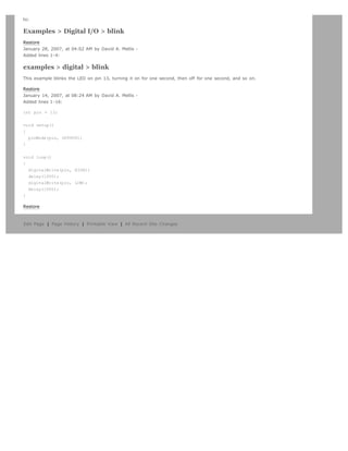
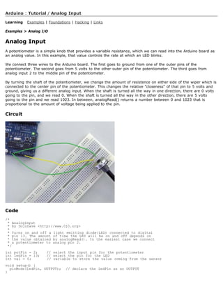
![pinMode(pins[i], OUTPUT); // set each pin as an output
}
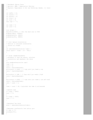
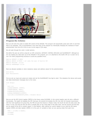
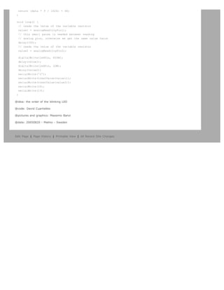
void loop()
{
int i;
for (i = 0; i < num_pins; i++) { // loop through each pin...
digitalWrite(pins[i], HIGH); // turning it on,
delay(timer); // pausing,
digitalWrite(pins[i], LOW); // and turning it off.
}
for (i = num_pins - 1; i >= 0; i--) {
digitalWrite(pins[i], HIGH);
delay(timer);
digitalWrite(pins[i], LOW);
}
}
Edit Page | Page History | Printable View | All Recent Site Changes](https://image.slidesharecdn.com/arduino-learning-111105084504-phpapp01/85/Arduino-learning-16-320.jpg)

![Arduino search
Buy | Download | Getting Started | Learning | Reference | Hardware | FAQ Blog » | Forum » | Playground »
Learning Examples | Foundations | Hacking | Links
Examples > Analog I/O
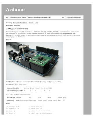
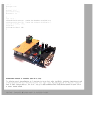
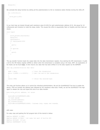
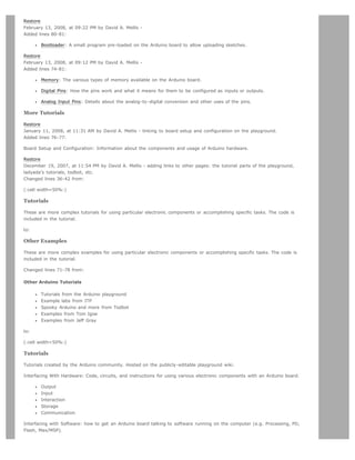
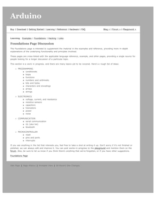
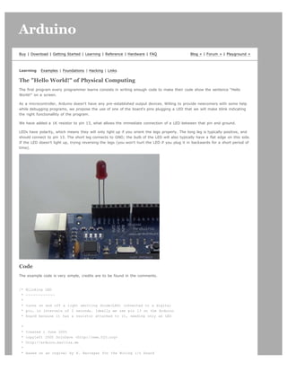
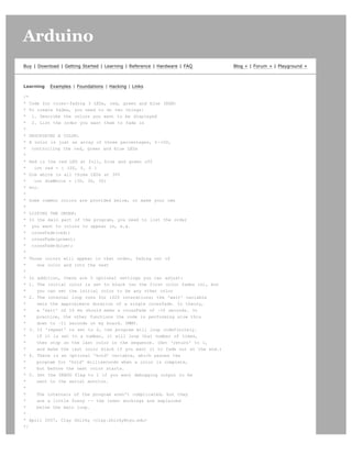
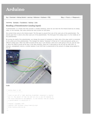
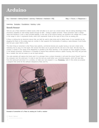
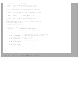
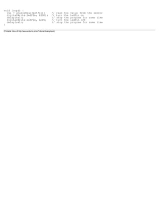
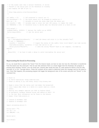
Smoothing
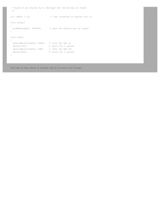
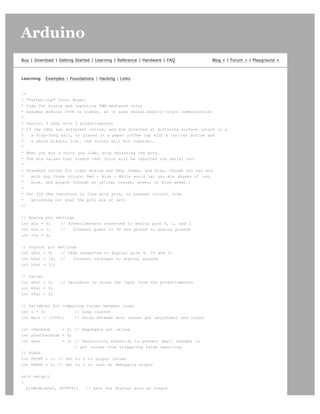
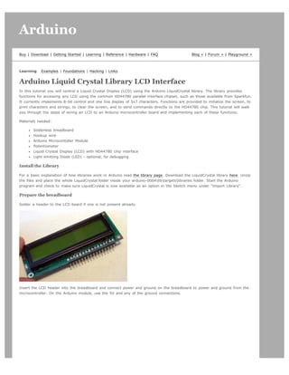
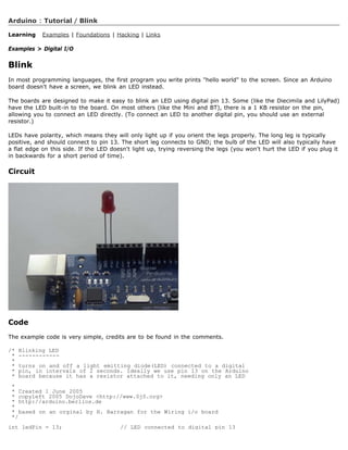
Reads repeatedly from an analog input, calculating a running average and printing it to the computer. Demonstrates the use
of arrays.
Circuit
Potentiometer on analog input pin 0.
Code
// Define the number of samples to keep track of. The higher the number,
// the more the readings will be smoothed, but the slower the output will
// respond to the input. Using a #define rather than a normal variable lets
// use this value to determine the size of the readings array.
#define NUMREADINGS 10
int readings[NUMREADINGS]; // the readings from the analog input
int index = 0; // the index of the current reading
int total = 0; // the running total
int average = 0; // the average
int inputPin = 0;
void setup()
{
Serial.begin(9600); // initialize serial communication with computer
for (int i = 0; i < NUMREADINGS; i++)
readings[i] = 0; // initialize all the readings to 0
}
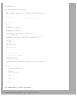
void loop()
{
total -= readings[index]; // subtract the last reading
readings[index] = analogRead(inputPin); // read from the sensor
total += readings[index]; // add the reading to the total
index = (index + 1); // advance to the next index
if (index >= NUMREADINGS) // if we're at the end of the array...
index = 0; // ...wrap around to the beginning
average = total / NUMREADINGS; // calculate the average
Serial.println(average); // send it to the computer (as ASCII digits)
}
Edit Page | Page History | Printable View | All Recent Site Changes](https://image.slidesharecdn.com/arduino-learning-111105084504-phpapp01/85/Arduino-learning-22-320.jpg)

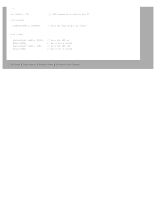
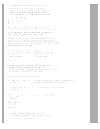
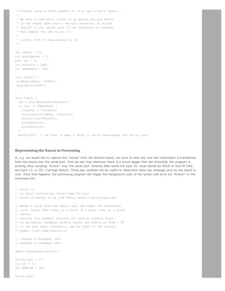
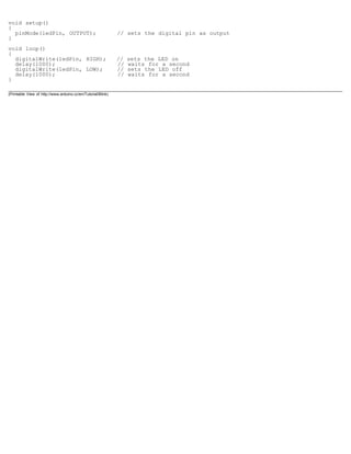
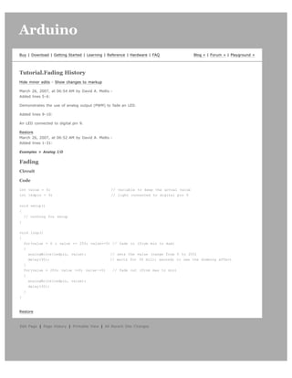
![// select the port corresponding to your Arduino board. The last
// parameter (e.g. 9600) is the speed of the communication. It
// has to correspond to the value passed to Serial.begin() in your
// Arduino sketch.
port = new Serial(this, Serial.list()[0], 9600);
// If you know the name of the port used by the Arduino board, you
// can specify it directly like this.
//port = new Serial(this, "COM1", 9600);
}
void draw()
{
// draw a gradient from black to white
for (int i = 0; i < 256; i++) {
stroke(i);
line(i, 0, i, 150);
}
// write the current X-position of the mouse to the serial port as
// a single byte
port.write(mouseX);
}
Edit Page | Page History | Printable View | All Recent Site Changes](https://image.slidesharecdn.com/arduino-learning-111105084504-phpapp01/85/Arduino-learning-26-320.jpg)
![Arduino search
Buy | Download | Getting Started | Learning | Reference | Hardware | FAQ Blog » | Forum » | Playground »
Learning Examples | Foundations | Hacking | Links
Examples > Communication
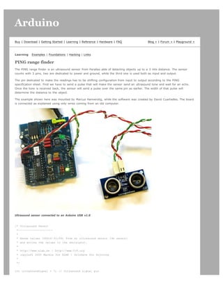
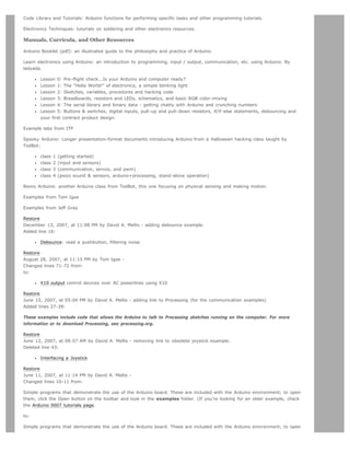
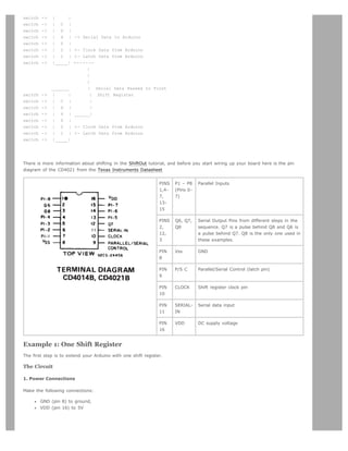
Graph
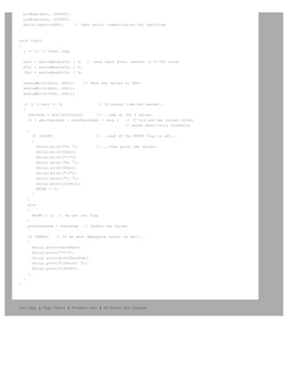
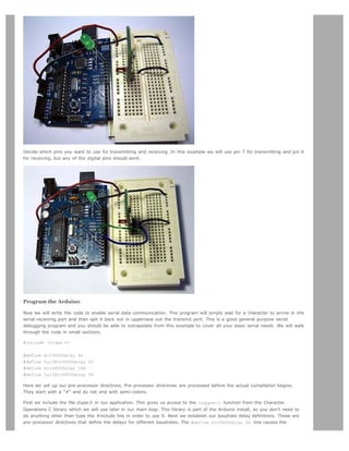
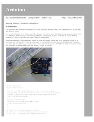
A simple example of communication from the Arduino board to the computer: the value of an analog input is printed. We call
this "serial" communication because the connection appears to both the Arduino and the computer as an old-fashioned serial
port, even though it may actually use a USB cable.
You can use the Arduino serial monitor to view the sent data, or it can be read by Processing (see code below), Flash, PD,
Max/MSP, etc.
Circuit
An analog input connected to analog input pin 0.
Code
void setup()
{
Serial.begin(9600);
}
void loop()
{
Serial.println(analogRead(0));
delay(20);
}
Processing Code
// Graph
// by David A. Mellis
//
// Demonstrates reading data from the Arduino board by graphing the
// values received.
//
// based on Analog In
// by <a href="http://itp.jtnimoy.com">Josh Nimoy</a>.
import processing.serial.*;
Serial port;
String buff = "";
int NEWLINE = 10;
// Store the last 64 values received so we can graph them.
int[] values = new int[64];
void setup()
{
size(512, 256);
println("Available serial ports:");
println(Serial.list());](https://image.slidesharecdn.com/arduino-learning-111105084504-phpapp01/85/Arduino-learning-27-320.jpg)
![// Uses the first port in this list (number 0). Change this to
// select the port corresponding to your Arduino board. The last
// parameter (e.g. 9600) is the speed of the communication. It
// has to correspond to the value passed to Serial.begin() in your
// Arduino sketch.
port = new Serial(this, Serial.list()[0], 9600);
// If you know the name of the port used by the Arduino board, you
// can specify it directly like this.
//port = new Serial(this, "COM1", 9600);
}
void draw()
{
background(53);
stroke(255);
// Graph the stored values by drawing a lines between them.
for (int i = 0; i < 63; i++)
line(i * 8, 255 - values[i], (i + 1) * 8, 255 - values[i + 1]);
while (port.available() > 0)
serialEvent(port.read());
}
void serialEvent(int serial)
{
if (serial != NEWLINE) {
// Store all the characters on the line.
buff += char(serial);
} else {
// The end of each line is marked by two characters, a carriage
// return and a newline. We're here because we've gotten a newline,
// but we still need to strip off the carriage return.
buff = buff.substring(0, buff.length()-1);
// Parse the String into an integer. We divide by 4 because
// analog inputs go from 0 to 1023 while colors in Processing
// only go from 0 to 255.
int val = Integer.parseInt(buff)/4;
// Clear the value of "buff"
buff = "";
// Shift over the existing values to make room for the new one.
for (int i = 0; i < 63; i++)
values[i] = values[i + 1];
// Add the received value to the array.
values[63] = val;
}
}
Edit Page | Page History | Printable View | All Recent Site Changes](https://image.slidesharecdn.com/arduino-learning-111105084504-phpapp01/85/Arduino-learning-28-320.jpg)
![{
size(200, 200);
noStroke();
frameRate(10);
// List all the available serial ports in the output pane.
// You will need to choose the port that the Arduino board is
// connected to from this list. The first port in the list is
// port #0 and the third port in the list is port #2.
println(Serial.list());
// Open the port that the Arduino board is connected to (in this case #0)
// Make sure to open the port at the same speed Arduino is using (9600bps)
port = new Serial(this, Serial.list()[0], 9600);
}
// function to test if mouse is over square
boolean mouseOverRect()
{
return ((mouseX >= 50)&&(mouseX <= 150)&&(mouseY >= 50)&(mouseY <= 150));
}
void draw()
{
background(#222222);
if(mouseOverRect()) // if mouse is over square
{
fill(#BBBBB0); // change color
port.write('H'); // send an 'H' to indicate mouse is over square
} else {
fill(#666660); // change color
port.write('L'); // send an 'L' otherwise
}
rect(50, 50, 100, 100); // draw square
}
Edit Page | Page History | Printable View | All Recent Site Changes](https://image.slidesharecdn.com/arduino-learning-111105084504-phpapp01/85/Arduino-learning-30-320.jpg)

![int NEWLINE = 10;
Serial port;
void setup()
{
size(200, 200);
// Print a list in case COM1 doesn't work out
println("Available serial ports:");
println(Serial.list());
//port = new Serial(this, "COM1", 9600);
// Uses the first available port
port = new Serial(this, Serial.list()[0], 9600);
}
void draw()
{
while (port.available() > 0) {
serialEvent(port.read());
}
background(rval, gval, bval);
}
void serialEvent(int serial)
{
// If the variable "serial" is not equal to the value for
// a new line, add the value to the variable "buff". If the
// value "serial" is equal to the value for a new line,
// save the value of the buffer into the variable "val".
if(serial != NEWLINE) {
buff += char(serial);
} else {
// The first character tells us which color this value is for
char c = buff.charAt(0);
// Remove it from the string
buff = buff.substring(1);
// Discard the carriage return at the end of the buffer
buff = buff.substring(0, buff.length()-1);
// Parse the String into an integer
if (c == 'R')
rval = Integer.parseInt(buff);
else if (c == 'G')
gval = Integer.parseInt(buff);
else if (c == 'B')
bval = Integer.parseInt(buff);
// Clear the value of "buff"
buff = "";
}
}
Edit Page | Page History | Printable View | All Recent Site Changes](https://image.slidesharecdn.com/arduino-learning-111105084504-phpapp01/85/Arduino-learning-32-320.jpg)
![Code
/* Controle_LEDcirle_with_joystik
* ------------
* This program controles a cirle of 8 LEDs through a joystick
*
* First it reads two analog pins that are connected
* to a joystick made of two potentiometers
*
* This input is interpreted as a coordinate (x,y)
*
* The program then calculates to which of the 8
* possible zones belogns the coordinate (x,y)
*
* Finally it ligths up the LED which is placed in the
* detected zone
*
* @authors: Cristina Hoffmann and Gustavo Jose Valera
* @hardware: Cristina Hofmann and Gustavo Jose Valera
* @context: Arduino Workshop at medialamadrid
*/
// Declaration of Variables
int ledPins [] = { 2,3,4,5,6,7,8,9 }; // Array of 8 leds mounted in a circle
int ledVerde = 13;
int espera = 40; // Time you should wait for turning on the leds
int joyPin1 = 0; // slider variable connecetd to analog pin 0
int joyPin2 = 1; // slider variable connecetd to analog pin 1
int coordX = 0; // variable to read the value from the analog pin 0
int coordY = 0; // variable to read the value from the analog pin 1](https://image.slidesharecdn.com/arduino-learning-111105084504-phpapp01/85/Arduino-learning-38-320.jpg)
![int centerX = 500; // we measured the value for the center of the joystick
int centerY = 500;
int actualZone = 0;
int previousZone = 0;
// Asignment of the pins
void setup()
{
int i;
beginSerial(9600);
pinMode (ledVerde, OUTPUT);
for (i=0; i< 8; i++)
{
pinMode(ledPins[i], OUTPUT);
}
}
// function that calculates the slope of the line that passes through the points
// x1, y1 and x2, y2
int calculateSlope(int x1, int y1, int x2, int y2)
{
return ((y1-y2) / (x1-x2));
}
// function that calculates in which of the 8 possible zones is the coordinate x y, given the center cx,
cy
int calculateZone (int x, int y, int cx, int cy)
{
int alpha = calculateSlope(x,y, cx,cy); // slope of the segment betweent the point and the center
if (x > cx)
{
if (y > cy) // first cuadrant
{
if (alpha > 1) // The slope is > 1, thus higher part of the first quadrant
return 0;
else
return 1; // Otherwise the point is in the lower part of the first quadrant
}
else // second cuadrant
{
if (alpha > -1)
return 2;
else
return 3;
}
}
else
{
if (y < cy) // third cuadrant
{
if (alpha > 1)
return 4;
else
return 5;
}
else // fourth cuadrant
{
if (alpha > -1)
return 6;
else
return 7;
}
}
}](https://image.slidesharecdn.com/arduino-learning-111105084504-phpapp01/85/Arduino-learning-39-320.jpg)
![void loop() {
digitalWrite(ledVerde, HIGH); // flag to know we entered the loop, you can erase this if you want
// reads the value of the variable resistors
coordX = analogRead(joyPin1);
coordY = analogRead(joyPin2);
// We calculate in which x
actualZone = calculateZone(coordX, coordY, centerX, centerY);
digitalWrite (ledPins[actualZone], HIGH);
if (actualZone != previousZone)
digitalWrite (ledPins[previousZone], LOW);
// we print int the terminal, the cartesian value of the coordinate, and the zone where it belongs.
//This is not necesary for a standalone version
serialWrite('C');
serialWrite(32); // print space
printInteger(coordX);
serialWrite(32); // print space
printInteger(coordY);
serialWrite(10);
serialWrite(13);
serialWrite('Z');
serialWrite(32); // print space
printInteger(actualZone);
serialWrite(10);
serialWrite(13);
// But this is necesary so, don't delete it!
previousZone = actualZone;
// delay (500);
}
@idea: Cristina Hoffmann and Gustavo Jose Valera
@code: Cristina Hoffmann and Gustavo Jose Valera
@pictures and graphics: Cristina Hoffmann
@date: 20051008 - Madrid - Spain
Edit Page | Page History | Printable View | All Recent Site Changes](https://image.slidesharecdn.com/arduino-learning-111105084504-phpapp01/85/Arduino-learning-40-320.jpg)

![*
* Each note has a frequency, created by varying the period of
* vibration, measured in microseconds. We'll use pulse-width
* modulation (PWM) to create that vibration.
* We calculate the pulse-width to be half the period; we pulse
* the speaker HIGH for 'pulse-width' microseconds, then LOW
* for 'pulse-width' microseconds.
* This pulsing creates a vibration of the desired frequency.
*
* (cleft) 2005 D. Cuartielles for K3
* Refactoring and comments 2006 clay.shirky@nyu.edu
* See NOTES in comments at end for possible improvements
*/
// TONES ==========================================
// Start by defining the relationship between
// note, period, & frequency.
#define c 3830 // 261 Hz
#define d 3400 // 294 Hz
#define e 3038 // 329 Hz
#define f 2864 // 349 Hz
#define g 2550 // 392 Hz
#define a 2272 // 440 Hz
#define b 2028 // 493 Hz
#define C 1912 // 523 Hz
// Define a special note, 'R', to represent a rest
#define R 0
// SETUP ============================================
// Set up speaker on a PWM pin (digital 9, 10 or 11)
int speakerOut = 9;
// Do we want debugging on serial out? 1 for yes, 0 for no
int DEBUG = 1;
void setup() {
pinMode(speakerOut, OUTPUT);
if (DEBUG) {
Serial.begin(9600); // Set serial out if we want debugging
}
}
// MELODY and TIMING =======================================
// melody[] is an array of notes, accompanied by beats[],
// which sets each note's relative length (higher #, longer note)
int melody[] = { C, b, g, C, b, e, R, C, c, g, a, C };
int beats[] = { 16, 16, 16, 8, 8, 16, 32, 16, 16, 16, 8, 8 };
int MAX_COUNT = sizeof(melody) / 2; // Melody length, for looping.
// Set overall tempo
long tempo = 10000;
// Set length of pause between notes
int pause = 1000;
// Loop variable to increase Rest length
int rest_count = 100; //<-BLETCHEROUS HACK; See NOTES
// Initialize core variables
int tone = 0;
int beat = 0;
long duration = 0;
// PLAY TONE ==============================================
// Pulse the speaker to play a tone for a particular duration
void playTone() {
long elapsed time = 0;](https://image.slidesharecdn.com/arduino-learning-111105084504-phpapp01/85/Arduino-learning-58-320.jpg)
![if (tone > 0) { // if this isn't a Rest beat, while the tone has
// played less long than 'duration', pulse speaker HIGH and LOW
while (elapsed_time < duration) {
digitalWrite(speakerOut,HIGH);
delayMicroseconds(tone / 2);
// DOWN
digitalWrite(speakerOut, LOW);
delayMicroseconds(tone / 2);
// Keep track of how long we pulsed
elapsed_time += (tone);
}
}
else { // Rest beat; loop times delay
for (int j = 0; j < rest_count; j++) { // See NOTE on rest_count
delayMicroseconds(duration);
}
}
}
// LET THE WILD RUMPUS BEGIN =============================
void loop() {
// Set up a counter to pull from melody[] and beats[]
for (int i=0; i<MAX_COUNT; i++) {
tone = melody[i];
beat = beats[i];
duration = beat * tempo; // Set up timing
playTone();
// A pause between notes...
delayMicroseconds(pause);
if (DEBUG) { // If debugging, report loop, tone, beat, and duration
Serial.print(i);
Serial.print(":");
Serial.print(beat);
Serial.print(" ");
Serial.print(tone);
Serial.print(" ");
Serial.println(duration);
}
}
}
/*
* NOTES
* The program purports to hold a tone for 'duration' microseconds.
* Lies lies lies! It holds for at least 'duration' microseconds, _plus_
* any overhead created by incremeting elapsed_time (could be in excess of
* 3K microseconds) _plus_ overhead of looping and two digitalWrites()
*
* As a result, a tone of 'duration' plays much more slowly than a rest
* of 'duration.' rest_count creates a loop variable to bring 'rest' beats
* in line with 'tone' beats of the same length.
*
* rest_count will be affected by chip architecture and speed, as well as
* overhead from any program mods. Past behavior is no guarantee of future
* performance. Your mileage may vary. Light fuse and get away.
*
* This could use a number of enhancements:
* ADD code to let the programmer specify how many times the melody should](https://image.slidesharecdn.com/arduino-learning-111105084504-phpapp01/85/Arduino-learning-59-320.jpg)
![* loop before stopping
* ADD another octave
* MOVE tempo, pause, and rest_count to #define statements
* RE-WRITE to include volume, using analogWrite, as with the second program at
* http://www.arduino.cc/en/Tutorial/PlayMelody
* ADD code to make the tempo settable by pot or other input device
* ADD code to take tempo or volume settable by serial communication
* (Requires 0005 or higher.)
* ADD code to create a tone offset (higer or lower) through pot etc
* REPLACE random melody with opening bars to 'Smoke on the Water'
*/
Second version, with volume control set using analogWrite()
/* Play Melody
* -----------
*
* Program to play melodies stored in an array, it requires to know
* about timing issues and about how to play tones.
*
* The calculation of the tones is made following the mathematical
* operation:
*
* timeHigh = 1/(2 * toneFrequency) = period / 2
*
* where the different tones are described as in the table:
*
* note frequency period PW (timeHigh)
* c 261 Hz 3830 1915
* d 294 Hz 3400 1700
* e 329 Hz 3038 1519
* f 349 Hz 2864 1432
* g 392 Hz 2550 1275
* a 440 Hz 2272 1136
* b 493 Hz 2028 1014
* C 523 Hz 1912 956
*
* (cleft) 2005 D. Cuartielles for K3
*/
int ledPin = 13;
int speakerOut = 9;
byte names[] = {'c', 'd', 'e', 'f', 'g', 'a', 'b', 'C'};
int tones[] = {1915, 1700, 1519, 1432, 1275, 1136, 1014, 956};
byte melody[] = "2d2a1f2c2d2a2d2c2f2d2a2c2d2a1f2c2d2a2a2g2p8p8p8p";
// count length: 1 2 3 4 5 6 7 8 9 0 1 2 3 4 5 6 7 8 9 0 1 2 3 4 5 6 7 8 9 0
// 10 20 30
int count = 0;
int count2 = 0;
int count3 = 0;
int MAX_COUNT = 24;
int statePin = LOW;
void setup() {
pinMode(ledPin, OUTPUT);
}
void loop() {
analogWrite(speakerOut, 0);
for (count = 0; count < MAX_COUNT; count++) {
statePin = !statePin;
digitalWrite(ledPin, statePin);
for (count3 = 0; count3 <= (melody[count*2] - 48) * 30; count3++) {](https://image.slidesharecdn.com/arduino-learning-111105084504-phpapp01/85/Arduino-learning-60-320.jpg)
![for (count2=0;count2<8;count2++) {
if (names[count2] == melody[count*2 + 1]) {
analogWrite(speakerOut,500);
delayMicroseconds(tones[count2]);
analogWrite(speakerOut, 0);
delayMicroseconds(tones[count2]);
}
if (melody[count*2 + 1] == 'p') {
// make a pause of a certain size
analogWrite(speakerOut, 0);
delayMicroseconds(500);
}
}
}
}
}
Edit Page | Page History | Printable View | All Recent Site Changes](https://image.slidesharecdn.com/arduino-learning-111105084504-phpapp01/85/Arduino-learning-61-320.jpg)
![* of documentation to be found on the internet.
*
* (cleft) 2005 DojoDave for K3
*
*/
int DI = 12;
int RW = 11;
int DB[] = {3, 4, 5, 6, 7, 8, 9, 10};
int Enable = 2;
void LcdCommandWrite(int value) {
// poll all the pins
int i = 0;
for (i=DB[0]; i <= DI; i++) {
digitalWrite(i,value & 01);
value >>= 1;
}
digitalWrite(Enable,LOW);
delayMicroseconds(1);
// send a pulse to enable
digitalWrite(Enable,HIGH);
delayMicroseconds(1); // pause 1 ms according to datasheet
digitalWrite(Enable,LOW);
delayMicroseconds(1); // pause 1 ms according to datasheet
}
void LcdDataWrite(int value) {
// poll all the pins
int i = 0;
digitalWrite(DI, HIGH);
digitalWrite(RW, LOW);
for (i=DB[0]; i <= DB[7]; i++) {
digitalWrite(i,value & 01);
value >>= 1;
}
digitalWrite(Enable,LOW);
delayMicroseconds(1);
// send a pulse to enable
digitalWrite(Enable,HIGH);
delayMicroseconds(1);
digitalWrite(Enable,LOW);
delayMicroseconds(1); // pause 1 ms according to datasheet
}
void setup (void) {
int i = 0;
for (i=Enable; i <= DI; i++) {
pinMode(i,OUTPUT);
}
delay(100);
// initiatize lcd after a short pause
// needed by the LCDs controller
LcdCommandWrite(0x30); // function set:
// 8-bit interface, 1 display lines, 5x7 font
delay(64);
LcdCommandWrite(0x30); // function set:
// 8-bit interface, 1 display lines, 5x7 font
delay(50);
LcdCommandWrite(0x30); // function set:
// 8-bit interface, 1 display lines, 5x7 font
delay(20);
LcdCommandWrite(0x06); // entry mode set:
// increment automatically, no display shift
delay(20);](https://image.slidesharecdn.com/arduino-learning-111105084504-phpapp01/85/Arduino-learning-65-320.jpg)
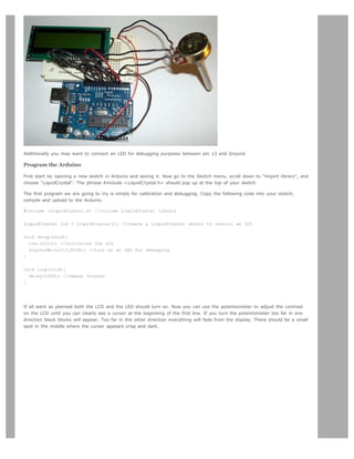
![This is all great fun, but who really wants to type out each letter of a message indivually? Enter the printIn() function. Simply
initialize a string, pass it to printIn(), and now we have ourselves a proper hello world program.
#include <LiquidCrystal.h> //include LiquidCrystal library
LiquidCrystal lcd = LiquidCrystal(); //create a LiquidCrystal object to control an LCD
char string1[] = "Hello!"; //variable to store the string "Hello!"
void setup(void){
lcd.init(); //initialize the LCD
digitalWrite(13,HIGH); //turn on an LED for debugging
}
void loop(void){
lcd.clear(); //clear the display
delay(1000); //delay 1000 ms to view change
lcd.printIn(string1); //send the string to the LCD
delay(1000); //delay 1000 ms to view change
} //repeat forever
Finally, you should know there is a lot of functionality in the HD44780 chip interface that is not drawn out into Arduino
functions. If you are feeling ambitious glance over the datasheet and try out some of the direct commands using the
commandWrite() function. For example, commandWrite(2) tells the board to move the cursor back to starting position. Here
is an example:
#include <LiquidCrystal.h> //include LiquidCrystal library
LiquidCrystal lcd = LiquidCrystal(); //create a LiquidCrystal object to control an LCD
char string1[] = "Hello!"; //variable to store the string "Hello!"
void setup(void){
lcd.init(); //initialize the LCD
digitalWrite(13,HIGH); //turn on an LED for debugging
}
void loop(void){
lcd.commandWrite(2); //bring the cursor to the starting position
delay(1000); //delay 1000 ms to view change
lcd.printIn(string1); //send the string to the LCD
delay(1000); //delay 1000 ms to view change
} //repeat forever
This code makes the cursor jump back and forth between the end of the message an the home position.
To interface an LCD directly in Arduino code see this example.
LCD interface library and tutorial by Heather Dewey-Hagborg
Edit Page | Page History | Printable View | All Recent Site Changes](https://image.slidesharecdn.com/arduino-learning-111105084504-phpapp01/85/Arduino-learning-71-320.jpg)
![Arduino search
Buy | Download | Getting Started | Learning | Reference | Hardware | FAQ Blog » | Forum » | Playground »
Learning Examples | Foundations | Hacking | Links
Unipolar Stepper Motor
This page shows two examples on how to drive a unipolar stepper motor. These motors can be found in old floppy drives and
are easy to control. The one we use has 6 connectors of which one is power (VCC) and the other four are used to drive the
motor sending synchronous signals.
The first example is the basic code to make the motor spin in one direction. It is aiming those that have no knowledge in
how to control stepper motors. The second example is coded in a more complex way, but allows to make the motor spin at
different speeds, in both directions, and controlling both from a potentiometer.
The prototyping board has been populated with a 10K potentiomenter that we connect to an analog input, and a ULN2003A
driver. This chip has a bunch of transistors embedded in a single housing. It allows the connection of devices and
components that need much higher current than the ones that the ATMEGA8 from our Arduino board can offer.
Picture of a protoboard supporting the ULN2003A and a potentiometer
Example 1: Simple example
/* Stepper Copal
* -------------
*
* Program to drive a stepper motor coming from a 5'25 disk drive
* according to the documentation I found, this stepper: "[...] motor
* made by Copal Electronics, with 1.8 degrees per step and 96 ohms
* per winding, with center taps brought out to separate leads [...]"
* [http://www.cs.uiowa.edu/~jones/step/example.html]
*](https://image.slidesharecdn.com/arduino-learning-111105084504-phpapp01/85/Arduino-learning-72-320.jpg)
![* It is a unipolar stepper motor with 5 wires:
*
* - red: power connector, I have it at 5V and works fine
* - orange and black: coil 1
* - brown and yellow: coil 2
*
* (cleft) 2005 DojoDave for K3
* http://www.0j0.org | http://arduino.berlios.de
*
* @author: David Cuartielles
* @date: 20 Oct. 2005
*/
int motorPin1 = 8;
int motorPin2 = 9;
int motorPin3 = 10;
int motorPin4 = 11;
int delayTime = 500;
void setup() {
pinMode(motorPin1, OUTPUT);
pinMode(motorPin2, OUTPUT);
pinMode(motorPin3, OUTPUT);
pinMode(motorPin4, OUTPUT);
}
void loop() {
digitalWrite(motorPin1, HIGH);
digitalWrite(motorPin2, LOW);
digitalWrite(motorPin3, LOW);
digitalWrite(motorPin4, LOW);
delay(delayTime);
digitalWrite(motorPin1, LOW);
digitalWrite(motorPin2, HIGH);
digitalWrite(motorPin3, LOW);
digitalWrite(motorPin4, LOW);
delay(delayTime);
digitalWrite(motorPin1, LOW);
digitalWrite(motorPin2, LOW);
digitalWrite(motorPin3, HIGH);
digitalWrite(motorPin4, LOW);
delay(delayTime);
digitalWrite(motorPin1, LOW);
digitalWrite(motorPin2, LOW);
digitalWrite(motorPin3, LOW);
digitalWrite(motorPin4, HIGH);
delay(delayTime);
}
Example 2: Stepper Unipolar Advanced
/* Stepper Unipolar Advanced
* -------------------------
*
* Program to drive a stepper motor coming from a 5'25 disk drive
* according to the documentation I found, this stepper: "[...] motor
* made by Copal Electronics, with 1.8 degrees per step and 96 ohms
* per winding, with center taps brought out to separate leads [...]"
* [http://www.cs.uiowa.edu/~jones/step/example.html]
*
* It is a unipolar stepper motor with 5 wires:
*](https://image.slidesharecdn.com/arduino-learning-111105084504-phpapp01/85/Arduino-learning-73-320.jpg)
![* - red: power connector, I have it at 5V and works fine
* - orange and black: coil 1
* - brown and yellow: coil 2
*
* (cleft) 2005 DojoDave for K3
* http://www.0j0.org | http://arduino.berlios.de
*
* @author: David Cuartielles
* @date: 20 Oct. 2005
*/
int motorPins[] = {8, 9, 10, 11};
int count = 0;
int count2 = 0;
int delayTime = 500;
int val = 0;
void setup() {
for (count = 0; count < 4; count++) {
pinMode(motorPins[count], OUTPUT);
}
}
void moveForward() {
if ((count2 == 0) || (count2 == 1)) {
count2 = 16;
}
count2>>=1;
for (count = 3; count >= 0; count--) {
digitalWrite(motorPins[count], count2>>count&0x01);
}
delay(delayTime);
}
void moveBackward() {
if ((count2 == 0) || (count2 == 1)) {
count2 = 16;
}
count2>>=1;
for (count = 3; count >= 0; count--) {
digitalWrite(motorPins[3 - count], count2>>count&0x01);
}
delay(delayTime);
}
void loop() {
val = analogRead(0);
if (val > 540) {
// move faster the higher the value from the potentiometer
delayTime = 2048 - 1024 * val / 512 + 1;
moveForward();
} else if (val < 480) {
// move faster the lower the value from the potentiometer
delayTime = 1024 * val / 512 + 1;
moveBackward();
} else {
delayTime = 1024;
}
}
References
In order to work out this example, we have been looking into quite a lot of documentation. The following links may be useful
for you to visit in order to understand the theory underlying behind stepper motors:](https://image.slidesharecdn.com/arduino-learning-111105084504-phpapp01/85/Arduino-learning-74-320.jpg)

![#define WREN 6
#define WRDI 4
#define RDSR 5
#define WRSR 1
#define READ 3
#define WRITE 2
Here we allocate the global variables we will be using later in the program. Note char buffer [128];. this is a 128 byte
array we will be using to store the data for the EEPROM write:
byte eeprom_output_data;
byte eeprom_input_data=0;
byte clr;
int address=0;
//data buffer
char buffer [128];
First we initialize our serial connection, set our input and output pin modes and set the SLAVESELECT line high to start. This
deselects the device and avoids any false transmission messages due to line noise:
void setup()
{
Serial.begin(9600);
pinMode(DATAOUT, OUTPUT);
pinMode(DATAIN, INPUT);
pinMode(SPICLOCK,OUTPUT);
pinMode(SLAVESELECT,OUTPUT);
digitalWrite(SLAVESELECT,HIGH); //disable device
Now we set the SPI Control register (SPCR) to the binary value 01010000. In the control register each bit sets a different
functionality. The eighth bit disables the SPI interrupt, the seventh bit enables the SPI, the sixth bit chooses transmission
with the most significant bit going first, the fifth bit puts the Arduino in Master mode, the fourth bit sets the data clock idle
when it is low, the third bit sets the SPI to sample data on the rising edge of the data clock, and the second and first bits
set the speed of the SPI to system speed / 4 (the fastest). After setting our control register up we read the SPI status
register (SPSR) and data register (SPDR) in to the junk clr variable to clear out any spurious data from past runs:
// SPCR = 01010000
//interrupt disabled,spi enabled,msb 1st,master,clk low when idle,
//sample on leading edge of clk,system clock/4 rate (fastest)
SPCR = (1<<SPE)|(1<<MSTR);
clr=SPSR;
clr=SPDR;
delay(10);
Here we fill our data array with numbers and send a write enable instruction to the EEPROM. The EEPROM MUST be write
enabled before every write instruction. To send the instruction we pull the SLAVESELECT line low, enabling the device, and
then send the instruction using the spi_transfer function. Note that we use the WREN opcode we defined at the beginning of
the program. Finally we pull the SLAVESELECT line high again to release it:
//fill buffer with data
fill_buffer();
//fill eeprom w/ buffer
digitalWrite(SLAVESELECT,LOW);
spi_transfer(WREN); //write enable
digitalWrite(SLAVESELECT,HIGH);
Now we pull the SLAVESELECT line low to select the device again after a brief delay. We send a WRITE instruction to tell the
EEPROM we will be sending data to record into memory. We send the 16 bit address to begin writing at in two bytes, Most
Significant Bit first. Next we send our 128 bytes of data from our buffer array, one byte after another without pause. Finally
we set the SLAVESELECT pin high to release the device and pause to allow the EEPROM to write the data:
delay(10);
digitalWrite(SLAVESELECT,LOW);
spi_transfer(WRITE); //write instruction
address=0;
spi_transfer((char)(address>>8)); //send MSByte address first](https://image.slidesharecdn.com/arduino-learning-111105084504-phpapp01/85/Arduino-learning-92-320.jpg)
![spi_transfer((char)(address)); //send LSByte address
//write 128 bytes
for (int I=0;I<128;I++)
{
spi_transfer(buffer[I]); //write data byte
}
digitalWrite(SLAVESELECT,HIGH); //release chip
//wait for eeprom to finish writing
delay(3000);
We end the setup function by sending the word "hi" plus a line feed out the built in serial port for debugging purposes. This
way if our data comes out looking funny later on we can tell it isn't just the serial port acting up:
Serial.print('h',BYTE);
Serial.print('i',BYTE);
Serial.print('n',BYTE);//debug
delay(1000);
}
In our main loop we just read one byte at a time from the EEPROM and print it out the serial port. We add a line feed and a
pause for readability. Each time through the loop we increment the eeprom address to read. When the address increments to
128 we turn it back to 0 because we have only filled 128 addresses in the EEPROM with data:
void loop()
{
eeprom_output_data = read_eeprom(address);
Serial.print(eeprom_output_data,DEC);
Serial.print('n',BYTE);
address++;
delay(500); //pause for readability
}
The fill_buffer function simply fills our data array with numbers 0 - 127 for each index in the array. This function could easily
be changed to fill the array with data relevant to your application:
void fill_buffer()
{
for (int I=0;I<128;I++)
{
buffer[I]=I;
}
}
The spi_transfer function loads the output data into the data transmission register, thus starting the SPI transmission. It polls
a bit to the SPI Status register (SPSR) to detect when the transmission is complete using a bit mask, SPIF. An explanation of
bit masks can be found here. It then returns any data that has been shifted in to the data register by the EEPROM:
char spi_transfer(volatile char data)
{
SPDR = data; // Start the transmission
while (!(SPSR & (1<<SPIF))) // Wait for the end of the transmission
{
};
return SPDR; // return the received byte
}
The read_eeprom function allows us to read data back out of the EEPROM. First we set the SLAVESELECT line low to enable
the device. Then we transmit a READ instruction, followed by the 16-bit address we wish to read from, Most Significant Bit
first. Next we send a dummy byte to the EEPROM for the purpose of shifting the data out. Finally we pull the SLAVESELECT
line high again to release the device after reading one byte, and return the data. If we wanted to read multiple bytes at a
time we could hold the SLAVESELECT line low while we repeated the data = spi_transfer(0xFF); up to 128 times for a full
page of data:
byte read_eeprom(int EEPROM_address)
{
//READ EEPROM
int data;
digitalWrite(SLAVESELECT,LOW);](https://image.slidesharecdn.com/arduino-learning-111105084504-phpapp01/85/Arduino-learning-93-320.jpg)
![spi_transfer(READ); //transmit read opcode
spi_transfer((char)(EEPROM_address>>8)); //send MSByte address first
spi_transfer((char)(EEPROM_address)); //send LSByte address
data = spi_transfer(0xFF); //get data byte
digitalWrite(SLAVESELECT,HIGH); //release chip, signal end transfer
return data;
}
For easy copy and pasting the full program text of this tutorial is below:
#define DATAOUT 11//MOSI
#define DATAIN 12//MISO
#define SPICLOCK 13//sck
#define SLAVESELECT 10//ss
//opcodes
#define WREN 6
#define WRDI 4
#define RDSR 5
#define WRSR 1
#define READ 3
#define WRITE 2
byte eeprom_output_data;
byte eeprom_input_data=0;
byte clr;
int address=0;
//data buffer
char buffer [128];
void fill_buffer()
{
for (int I=0;I<128;I++)
{
buffer[I]=I;
}
}
char spi_transfer(volatile char data)
{
SPDR = data; // Start the transmission
while (!(SPSR & (1<<SPIF))) // Wait the end of the transmission
{
};
return SPDR; // return the received byte
}
void setup()
{
Serial.begin(9600);
pinMode(DATAOUT, OUTPUT);
pinMode(DATAIN, INPUT);
pinMode(SPICLOCK,OUTPUT);
pinMode(SLAVESELECT,OUTPUT);
digitalWrite(SLAVESELECT,HIGH); //disable device
// SPCR = 01010000
//interrupt disabled,spi enabled,msb 1st,master,clk low when idle,
//sample on leading edge of clk,system clock/4 rate (fastest)
SPCR = (1<<SPE)|(1<<MSTR);
clr=SPSR;
clr=SPDR;
delay(10);
//fill buffer with data
fill_buffer();](https://image.slidesharecdn.com/arduino-learning-111105084504-phpapp01/85/Arduino-learning-94-320.jpg)
![//fill eeprom w/ buffer
digitalWrite(SLAVESELECT,LOW);
spi_transfer(WREN); //write enable
digitalWrite(SLAVESELECT,HIGH);
delay(10);
digitalWrite(SLAVESELECT,LOW);
spi_transfer(WRITE); //write instruction
address=0;
spi_transfer((char)(address>>8)); //send MSByte address first
spi_transfer((char)(address)); //send LSByte address
//write 128 bytes
for (int I=0;I<128;I++)
{
spi_transfer(buffer[I]); //write data byte
}
digitalWrite(SLAVESELECT,HIGH); //release chip
//wait for eeprom to finish writing
delay(3000);
Serial.print('h',BYTE);
Serial.print('i',BYTE);
Serial.print('n',BYTE);//debug
delay(1000);
}
byte read_eeprom(int EEPROM_address)
{
//READ EEPROM
int data;
digitalWrite(SLAVESELECT,LOW);
spi_transfer(READ); //transmit read opcode
spi_transfer((char)(EEPROM_address>>8)); //send MSByte address first
spi_transfer((char)(EEPROM_address)); //send LSByte address
data = spi_transfer(0xFF); //get data byte
digitalWrite(SLAVESELECT,HIGH); //release chip, signal end transfer
return data;
}
void loop()
{
eeprom_output_data = read_eeprom(address);
Serial.print(eeprom_output_data,DEC);
Serial.print('n',BYTE);
address++;
if (address == 128)
address = 0;
delay(500); //pause for readability
}
code and tutorial by Heather Dewey-Hagborg, photos by Thomas Dexter
Edit Page | Page History | Printable View | All Recent Site Changes](https://image.slidesharecdn.com/arduino-learning-111105084504-phpapp01/85/Arduino-learning-95-320.jpg)

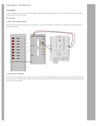
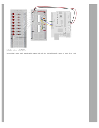
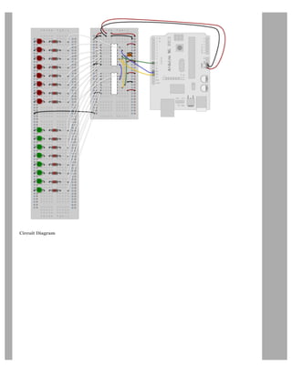
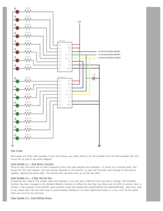
![Like sample 2.2, sample 2.3 also takes advantage of the new blinkAll_2bytes() function. 2.3's big difference from sample 1.3
is only that instead of just a single variable called “data” and a single array called “dataArray” you have to have a dataRED,
a dataGREEN, dataArrayRED, dataArrayGREEN defined up front. This means that line
data = dataArray[j];
becomes
dataRED = dataArrayRED[j];
dataGREEN = dataArrayGREEN[j];
and
shiftOut(dataPin, clockPin, data);
becomes
shiftOut(dataPin, clockPin, dataGREEN);
shiftOut(dataPin, clockPin, dataRED);
Edit Page | Page History | Printable View | All Recent Site Changes](https://image.slidesharecdn.com/arduino-learning-111105084504-phpapp01/85/Arduino-learning-111-320.jpg)


![LED as light sensor (en Francais)
Arduino and the Asuro robot
Using Arduino from the command line
Restore
May 11, 2007, at 06:06 AM by Paul Badger -
Changed lines 17-18 from:
to:
PWM all of the digital pins in a sinewave pattern
Restore
May 10, 2007, at 07:07 PM by Paul Badger -
Changed lines 36-37 from:
http://www.arduino.cc/cgi-bin/yabb2/YaBB.pl?num=1171076259 |Use a couple of Arduino pins as a capacitive
sensor]]
to:
Use two Arduino pins as a capacitive sensor
Restore
May 10, 2007, at 07:05 PM by Paul Badger -
Changed lines 36-37 from:
http://www.arduino.cc/cgi-bin/yabb2/YaBB.pl?num=1171076259 Use a couple of Arduino pins as a capacitive sensor
to:
http://www.arduino.cc/cgi-bin/yabb2/YaBB.pl?num=1171076259 |Use a couple of Arduino pins as a capacitive
sensor]]
Restore
May 10, 2007, at 07:04 PM by Paul Badger -
Changed lines 36-37 from:
to:
http://www.arduino.cc/cgi-bin/yabb2/YaBB.pl?num=1171076259 Use a couple of Arduino pins as a capacitive sensor
Restore
May 10, 2007, at 06:59 PM by Paul Badger -
Added line 39:
More sound ideas
Restore
April 24, 2007, at 03:40 PM by Clay Shirky -
Changed lines 13-14 from:
Dimming 3 LEDs with Pulse-Width Modulation (PWM)
to:
Simple Dimming 3 LEDs with Pulse-Width Modulation (PWM)
More complex dimming/color crossfader
Restore
February 08, 2007, at 12:02 PM by Carlyn Maw -
Changed lines 52-53 from:
to:
Multiple digital inputs with a CD4021 Shift Register
Restore
February 06, 2007, at 02:52 PM by Carlyn Maw -
Changed lines 52-54 from:
Multiple digital ins with a CD4021 Shift Register
to:
Restore](https://image.slidesharecdn.com/arduino-learning-111105084504-phpapp01/85/Arduino-learning-129-320.jpg)

![Arduino search
Buy | Download | Getting Started | Learning | Reference | Hardware | FAQ Blog » | Forum » | Playground »
Learning Examples | Foundations | Hacking | Links
Memory
There are three pools of memory in the microcontroller used on Arduino boards (ATmega168):
Flash memory (program space), is where the Arduino sketch is stored.
SRAM (static random access memory) is where the sketch creates and manipulates variables when it runs.
EEPROM is memory space that programmers can use to store long-term information.
Flash memory and EEPROM memory are non-volatile (the information persists after the power is turned off). SRAM is volatile
and will be lost when the power is cycled.
The ATmega168 chip has the following amounts of memory:
Flash 16k bytes (of which 2k is used for the bootloader)
SRAM 1024 bytes
EEPROM 512 bytes
Notice that there's not much SRAM available. It's easy to use it all up by having lots of strings in your program. For example,
a declaration like:
char message[] = I support the Cape Wind project.;
puts 32 bytes into SRAM (each character takes a byte). This might not seem like a lot, but it doesn't take long to get to
1024, especially if you have a large amount of text to send to a display, or a large lookup table, for example.
If you run out of SRAM, your program may fail in unexpected ways; it will appear to upload successfully, but not run, or run
strangely. To check if this is happening, you can try commenting out or shortening the strings or other data structures in
your sketch (without changing the code). If it then runs successfully, you're probably running out of SRAM. There are a few
things you can do to address this problem:
If your sketch talks to a program running on a (desktop/laptop) computer, you can try shifting data or calculations to
the computer, reducing the load on the Arduino.
If you have lookup tables or other large arrays, use the smallest data type necessary to store the values you need;
for example, an int takes up two bytes, while a byte uses only one (but can store a smaller range of values).
If you don't need to modify the strings or data while your sketch is running, you can store them in flash (program)
memory instead of SRAM; to do this, use the PROGMEM keyword.
To use the EEPROM, see the EEPROM library.
Foundations
Edit Page | Page History | Printable View | All Recent Site Changes](https://image.slidesharecdn.com/arduino-learning-111105084504-phpapp01/85/Arduino-learning-145-320.jpg)
![Arduino search
Buy | Download | Getting Started | Learning | Reference | Hardware | FAQ Blog » | Forum » | Playground »
Learning Examples | Foundations | Hacking | Links
Variables
A variable is a place to store a piece of data. It has a name, a value, and a type. For example, this statement (called a
declaration):
int pin = 13;
creates a variable whose name is pin, whose value is 13, and whose type is int. Later on in the program, you can refer to
this variable by its name, at which point its value will be looked up and used. For example, in this statement:
pinMode(pin, OUTPUT);
it is the value of pin (13) that will be passed to the pinMode() function. In this case, you don't actually need to use a
variable, this statement would work just as well:
pinMode(13, OUTPUT);
The advantage of a variable in this case is that you only need to specify the actual number of the pin once, but you can use
it lots of times. So if you later decide to change from pin 13 to pin 12, you only need to change one spot in the code. Also,
you can use a descriptive name to make the significance of the variable clear (e.g. a program controlling an RGB LED might
have variables called redPin, greenPin, and bluePin).
A variable has other advantages over a value like a number. Most importantly, you can change the value of a variable using
an assignment (indicated by an equals sign). For example:
pin = 12;
will change the value of the variable to 12. Notice that we don't specify the type of the variable: it's not changed by the
assignment. That is, the name of the variable is permanently associated with a type; only its value changes. [1] Note that
you have to declare a variable before you can assign a value to it. If you include the preceding statement in a program
without the first statement above, you'll get a message like: error: pin was not declared in this scope.
When you assign one variable to another, you're making a copy of its value and storing that copy in the location in memory
associated with the other variable. Changing one has no effect on the other. For example, after:
int pin = 13;
int pin2 = pin;
pin = 12;
only pin has the value 12; pin2 is still 13.
Now what, you might be wondering, did the word scope in that error message above mean? It refers to the part of your
program in which the variable can be used. This is determined by where you declare it. For example, if you want to be able
to use a variable anywhere in your program, you can declare at the top of your code. This is called a global variable; here's
an example:
int pin = 13;
void setup()
{
pinMode(pin, OUTPUT);
}
void loop()
{
digitalWrite(pin, HIGH);
}](https://image.slidesharecdn.com/arduino-learning-111105084504-phpapp01/85/Arduino-learning-147-320.jpg)
![As you can see, pin is used in both the setup() and loop() functions. Both functions are referring to the same variable, so
that changing it one will affect the value it has in the other, as in:
int pin = 13;
void setup()
{
pin = 12;
pinMode(pin, OUTPUT);
}
void loop()
{
digitalWrite(pin, HIGH);
}
Here, the digitalWrite() function called from loop() will be passed a value of 12, since that's the value that was assigned to
the variable in the setup() function.
If you only need to use a variable in a single function, you can declare it there, in which case its scope will be limited to that
function. For example:
void setup()
{
int pin = 13;
pinMode(pin, OUTPUT);
digitalWrite(pin, HIGH);
}
In this case, the variable pin can only be used inside the setup() function. If you try to do something like this:
void loop()
{
digitalWrite(pin, LOW); // wrong: pin is not in scope here.
}
you'll get the same message as before: error: 'pin' was not declared in this scope. That is, even though you've declared pin
somewhere in your program, you're trying to use it somewhere outside its scope.
Why, you might be wondering, wouldn't you make all your variables global? After all, if I don't know where I might need a
variable, why should I limit its scope to just one function? The answer is that it can make it easier to figure out what
happens to it. If a variable is global, its value could be changed anywhere in the code, meaning that you need to understand
the whole program to know what will happen to the variable. For example, if your variable has a value you didn't expect, it
can be much easier to figure out where the value came from if the variable has a limited scope.
[block scope] [size of variables]
[1] In some languages, like Python, types are associated with values, not variable names, and you can assign values of any
type to a variable. This is referred to as dynamic typing.
Edit Page | Page History | Printable View | All Recent Site Changes](https://image.slidesharecdn.com/arduino-learning-111105084504-phpapp01/85/Arduino-learning-148-320.jpg)


![// Output
int redPin = 9; // Red LED, connected to digital pin 9
int grnPin = 10; // Green LED, connected to digital pin 10
int bluPin = 11; // Blue LED, connected to digital pin 11
// Color arrays
int black[3] = { 0, 0, 0 };
int white[3] = { 100, 100, 100 };
int red[3] = { 100, 0, 0 };
int green[3] = { 0, 100, 0 };
int blue[3] = { 0, 0, 100 };
int yellow[3] = { 40, 95, 0 };
int dimWhite[3] = { 30, 30, 30 };
// etc.
// Set initial color
int redVal = black[0];
int grnVal = black[1];
int bluVal = black[2];
int wait = 10; // 10ms internal crossFade delay; increase for slower fades
int hold = 0; // Optional hold when a color is complete, before the next crossFade
int DEBUG = 1; // DEBUG counter; if set to 1, will write values back via serial
int loopCount = 60; // How often should DEBUG report?
int repeat = 3; // How many times should we loop before stopping? (0 for no stop)
int j = 0; // Loop counter for repeat
// Initialize color variables
int prevR = redVal;
int prevG = grnVal;
int prevB = bluVal;
// Set up the LED outputs
void setup()
{
pinMode(redPin, OUTPUT); // sets the pins as output
pinMode(grnPin, OUTPUT);
pinMode(bluPin, OUTPUT);
if (DEBUG) { // If we want to see values for debugging...
Serial.begin(9600); // ...set up the serial ouput
}
}
// Main program: list the order of crossfades
void loop()
{
crossFade(red);
crossFade(green);
crossFade(blue);
crossFade(yellow);
if (repeat) { // Do we loop a finite number of times?
j += 1;
if (j = repeat) { // Are we there yet?
exit(j); // If so, stop.
}
}
}
/* BELOW THIS LINE IS THE MATH -- YOU SHOULDN'T NEED TO CHANGE THIS FOR THE BASICS
*
* The program works like this:
* Imagine a crossfade that moves the red LED from 0-10,](https://image.slidesharecdn.com/arduino-learning-111105084504-phpapp01/85/Arduino-learning-171-320.jpg)
![void crossFade(int color[3]) {
// Convert to 0-255
int R = (color[0] * 255) / 100;
int G = (color[1] * 255) / 100;
int B = (color[2] * 255) / 100;
int stepR = calculateStep(prevR, R);
int stepG = calculateStep(prevG, G);
int stepB = calculateStep(prevB, B);
for (int i = 0; i = 1020; i++) {
redVal = calculateVal(stepR, redVal, i);
grnVal = calculateVal(stepG, grnVal, i);
bluVal = calculateVal(stepB, bluVal, i);
analogWrite(redPin, redVal); // Write current values to LED pins
analogWrite(grnPin, grnVal);
analogWrite(bluPin, bluVal);
delay(wait); // Pause for 'wait' milliseconds before resuming the loop
if (DEBUG) { // If we want serial output, print it at the
if (i == 0 or i % loopCount == 0) { // beginning, and every loopCount times
Serial.print(Loop/RGB: #);
Serial.print(i);
Serial.print( | );
Serial.print(redVal);
Serial.print( / );
Serial.print(grnVal);
Serial.print( / );
Serial.println(bluVal);
}
DEBUG += 1;
}
}
// Update current values for next loop
prevR = redVal;
prevG = grnVal;
prevB = bluVal;
delay(hold); // Pause for optional 'wait' milliseconds before resuming the loop
}
Edit Page | Page History | Printable View | All Recent Site Changes](https://image.slidesharecdn.com/arduino-learning-111105084504-phpapp01/85/Arduino-learning-173-320.jpg)
![delay(timer);
digitalWrite(pin3, LOW);
delay(timer);
}
Knight Rider 2
/* Knight Rider 2
* --------------
*
* Reducing the amount of code using for(;;).
*
*
* (cleft) 2005 K3, Malmo University
* @author: David Cuartielles
* @hardware: David Cuartielles, Aaron Hallborg
*/
int pinArray[] = {2, 3, 4, 5, 6, 7};
int count = 0;
int timer = 100;
void setup(){
// we make all the declarations at once
for (count=0;count6;count++) {
pinMode(pinArray[count], OUTPUT);
}
}
void loop() {
for (count=0;count6;count++) {
digitalWrite(pinArray[count], HIGH);
delay(timer);
digitalWrite(pinArray[count], LOW);
delay(timer);
}
for (count=5;count=0;count--) {
digitalWrite(pinArray[count], HIGH);
delay(timer);
digitalWrite(pinArray[count], LOW);
delay(timer);
}
}
Knight Rider 3
/* Knight Rider 3
* --------------
*
* This example concentrates on making the visuals fluid.
*
*
* (cleft) 2005 K3, Malmo University
* @author: David Cuartielles
* @hardware: David Cuartielles, Aaron Hallborg
*/
int pinArray[] = {2, 3, 4, 5, 6, 7};
int count = 0;
int timer = 30;
void setup(){](https://image.slidesharecdn.com/arduino-learning-111105084504-phpapp01/85/Arduino-learning-176-320.jpg)
![for (count=0;count6;count++) {
pinMode(pinArray[count], OUTPUT);
}
}
void loop() {
for (count=0;count5;count++) {
digitalWrite(pinArray[count], HIGH);
delay(timer);
digitalWrite(pinArray[count + 1], HIGH);
delay(timer);
digitalWrite(pinArray[count], LOW);
delay(timer*2);
}
for (count=5;count0;count--) {
digitalWrite(pinArray[count], HIGH);
delay(timer);
digitalWrite(pinArray[count - 1], HIGH);
delay(timer);
digitalWrite(pinArray[count], LOW);
delay(timer*2);
}
}
Edit Page | Page History | Printable View | All Recent Site Changes](https://image.slidesharecdn.com/arduino-learning-111105084504-phpapp01/85/Arduino-learning-177-320.jpg)
![*
* You can also control the length of the star's tail
* through the variable tail length
* First it reads two analog pins that are connected
* to a joystick made of two potentiometers
*
* @author: Cristina Hoffmann
* @hardware: Cristina Hofmann
*
*/
// Variable declaration
int pinArray [] = { 2,3,4,5,6,7,8,9,10,11,12 }; // Array where I declare the pins connected to the
LEDs
int controlLed = 13;
int waitNextLed = 100; // Time before I light up the next LED
int tailLength = 4; // Number of LEDs that stay lit befor I start turning them off, thus the tail
int lineSize = 11; // Number of LEDs connected (which also is the size of the pinArray)
// I asign the sens of the different Pins
void setup()
{
int i;
pinMode (controlLed, OUTPUT);
for (i=0; i lineSize; i++)
{
pinMode(pinArray[i], OUTPUT);
}
}
// Main loop
void loop()
{
int i;
int tailCounter = tailLength; // I set up the tail length in a counter
digitalWrite(controlLed, HIGH); // I make sure I enter the loop indicating it with this LED
for (i=0; ilineSize; i++)
{
digitalWrite(pinArray[i],HIGH); // I light up consecutively the LEDs
delay(waitNextLed); // This time variable controles how fast I light them up
if (tailCounter == 0)
{
digitalWrite(pinArray[i-tailLength],LOW); // I turn off the LEDs depending on my tailLength
}
else
if (tailCounter 0)
tailCounter--;
}
for (i=(lineSize-tailLength); ilineSize; i++)
{
digitalWrite(pinArray[i],LOW); // I turn off the LEDs
delay(waitNextLed); // This time variable controles how fast I light them upm, and turn off
as well
}
}
@idea: Cristina Hoffmann
@code: Cristina Hoffmann
@pictures and graphics: Cristina Hoffmann
@date: 20060203 - Rennes - France](https://image.slidesharecdn.com/arduino-learning-111105084504-phpapp01/85/Arduino-learning-179-320.jpg)


![if (1 0)
Changed line 50 from:
=]
to:
@]
Restore
January 28, 2007, at 04:26 AM by David A. Mellis -
Changed lines 15-19 from:
[@ // blink // http://www.arduino.cc/en/Tutorial/Blink int pin = 13;
to:
Code
The example code is very simple, credits are to be found in the comments.
[= /* Blinking LED
* ------------
*
* turns on and off a light emitting diode(LED) connected to a digital
* pin, in intervals of 2 seconds. Ideally we use pin 13 on the Arduino
* board because it has a resistor attached to it, needing only an LED
*
* Created 1 June 2005
* copyleft 2005 DojoDave http://www.0j0.org
* http://arduino.berlios.de
*
* based on an orginal by H. Barragan for the Wiring i/o board
*/
int ledPin = 13; // LED connected to digital pin 13
Changed line 39 from:
pinMode(pin, OUTPUT);
to:
pinMode(ledPin, OUTPUT); // sets the digital pin as output
Changed lines 44-47 from:
digitalWrite(pin, HIGH);
delay(1000);
digitalWrite(pin, LOW);
delay(1000);
to:
digitalWrite(ledPin, HIGH); // sets the LED on
delay(1000); // waits for a second
digitalWrite(ledPin, LOW); // sets the LED off
delay(1000); // waits for a second
Changed line 49 from:
@]
to:
=]
Restore
January 28, 2007, at 04:25 AM by David A. Mellis -
Changed lines 5-6 from:](https://image.slidesharecdn.com/arduino-learning-111105084504-phpapp01/85/Arduino-learning-211-320.jpg)


![Arduino search
Buy | Download | Getting Started | Learning | Reference | Hardware | FAQ Blog » | Forum » | Playground »
Tutorial.Loop History
Hide minor edits - Show changes to markup
September 23, 2007, at 08:37 PM by David A. Mellis -
Changed line 40 from:
digitalWrite(i, HIGH);
to:
digitalWrite(pins[i], HIGH);
Changed line 42 from:
digitalWrite(i, LOW);
to:
digitalWrite(pins[i], LOW);
Restore
April 22, 2007, at 12:20 PM by David A. Mellis -
Changed lines 18-19 from:
int timer = 100;
to:
int timer = 100; // The higher the number, the slower the timing. int pins[] = { 2, 3, 4, 5, 6, 7 }; // an array of pin
numbers int num_pins = 6; // the number of pins (i.e. the length of the array)
Changed lines 26-27 from:
for (i = 2; i = 7; i++)
pinMode(i, OUTPUT);
to:
for (i = 0; i num_pins; i++) // the array elements are numbered from 0 to num_pins - 1
pinMode(pins[i], OUTPUT); // set each pin as an output
Changed lines 34-39 from:
for (i = 2; i = 7; i++) {
to:
for (i = 0; i num_pins; i++) { // loop through each pin...
digitalWrite(pins[i], HIGH); // turning it on,
delay(timer); // pausing,
digitalWrite(pins[i], LOW); // and turning it off.
}
for (i = num_pins - 1; i = 0; i--) {
Deleted line 42:
delay(timer);
Deleted lines 43-48:
for (i = 7; i = 2; i--) {](https://image.slidesharecdn.com/arduino-learning-111105084504-phpapp01/85/Arduino-learning-233-320.jpg)
![Arduino : Tutorial / Loop
Learning Examples | Foundations | Hacking | Links
Examples Digital I/O
Loop
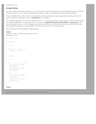
We also call this example Knight Rider in memory to a TV-series from the 80's where the famous David
Hasselhoff had an AI machine driving his Pontiac. The car had been augmented with plenty of LEDs in all possible
sizes performing flashy effects.
Thus we decided that in order to learn more about sequential programming and good programming techniques for
the I/O board, it would be interesting to use the Knight Rider as a metaphor.
This example makes use of 6 LEDs connected to the pins 2 - 7 on the board using 220 Ohm resistors. The first
code example will make the LEDs blink in a sequence, one by one using only digitalWrite(pinNum,HIGH/LOW)
and delay(time). The second example shows how to use a for(;;) construction to perform the very same thing,
but in fewer lines. The third and last example concentrates in the visual effect of turning the LEDs on/off in a more
softer way.
Circuit
Code
int timer = 100; // The higher the number, the slower the timing.
int pins[] = { 2, 3, 4, 5, 6, 7 }; // an array of pin numbers
int num_pins = 6; // the number of pins (i.e. the length of the array)
void setup()
{
int i;
for (i = 0; i num_pins; i++) // the array elements are numbered from 0 to num_pins - 1
pinMode(pins[i], OUTPUT); // set each pin as an output
}](https://image.slidesharecdn.com/arduino-learning-111105084504-phpapp01/85/Arduino-learning-236-320.jpg)
![void loop()
{
int i;
for (i = 0; i num_pins; i++) { // loop through each pin...
digitalWrite(pins[i], HIGH); // turning it on,
delay(timer); // pausing,
digitalWrite(pins[i], LOW); // and turning it off.
}
for (i = num_pins - 1; i = 0; i--) {
digitalWrite(pins[i], HIGH);
delay(timer);
digitalWrite(pins[i], LOW);
}
}
(Printable View of http://www.arduino.cc/en/Tutorial/Loop)](https://image.slidesharecdn.com/arduino-learning-111105084504-phpapp01/85/Arduino-learning-237-320.jpg)


![Changed lines 9-10 from:
The code example will capture the knock and if it is stronger than a certain threshold, it will send the string Knock! back to
the computer over the serial port. In order to see this text you could either use a terminal program, which will read data
from the serial port and show it in a window, or make your own program in e.g. Processing. Later in this article we propose a
program that works for the software designed by Reas and Fry.
to:
The code example will capture the knock and if it is stronger than a certain threshold, it will send the string Knock! back to
the computer over the serial port. In order to see this text you can use the Arduino serial monitor.
Changed line 15 from:
[=
to:
[@
Changed lines 50-117 from:
=]
Representing the Knock in Processing
If, e.g. we would like to capture this knock from the Arduino board, we have to look into how the information is transferred
from the board over the serial port. First we see that whenever there is a knock bigger that the threshold, the program is
printing (thus sending) Knock! over the serial port. Directly after sends the byte 10, what stands for EOLN or End Of LiNe,
and byte 13, or CR - Carriage Return. Those two symbols will be useful to determine when the message sent by the board is
over. Once that happens, the processing program will toggle the background color of the screen and print out Knock! in the
command line.
// Knock In
// by David Cuartielles http://www.0j0.org
// based on Analog In by Josh Nimoy http://itp.jtnimoy.com
// Reads a value from the serial port and makes the background
// color toggle when there is a knock on a piezo used as a knock
// sensor.
// Running this example requires you have an Arduino board
// as peripheral hardware sending values and adding an EOLN + CR
// in the end. More information can be found on the Arduino
// pages: http://www.arduino.cc
// Created 23 November 2005
// Updated 23 November 2005
import processing.serial.*;
String buff = ;
int val = 0;
int NEWLINE = 10;
Serial port;
void setup()
{
size(200, 200);
// Open your serial port
port = new Serial(this, COMXX, 9600); // -- SUBSTITUTE COMXX with your serial port name!!
}
void draw()
{
// Process each one of the serial port events](https://image.slidesharecdn.com/arduino-learning-111105084504-phpapp01/85/Arduino-learning-248-320.jpg)
![while (port.available() 0) {
serialEvent(port.read());
}
background(val);
}
void serialEvent(int serial)
{
if(serial != NEWLINE) {
buff += char(serial);
} else {
buff = buff.substring(1, buff.length()-1);
// Capture the string and print it to the commandline
// we have to take from position 1 because
// the Arduino sketch sends EOLN (10) and CR (13)
if (val == 0) {
val = 255;
} else {
val = 0;
}
println(buff);
// Clear the value of buff
buff = ;
}
}
to:
@]
Restore
March 25, 2007, at 03:25 AM by David A. Mellis -
Added lines 1-117:
Knock Sensor
Here we use a Piezo element to detect sound, what will allow us to use it as a knock sensor. We are taking advantage of the
processors capability to read analog signals through its ADC - analog to digital converter. These converters read a voltage
value and transform it into a value encoded digitally. In the case of the Arduino boards, we transform the voltage into a value
in the range 0..1024. 0 represents 0volts, while 1024 represents 5volts at the input of one of the six analog pins.
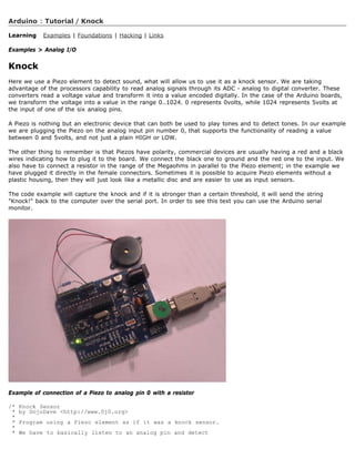
A Piezo is nothing but an electronic device that can both be used to play tones and to detect tones. In our example we are
plugging the Piezo on the analog input pin number 0, that supports the functionality of reading a value between 0 and 5volts,
and not just a plain HIGH or LOW.
The other thing to remember is that Piezos have polarity, commercial devices are usually having a red and a black wires
indicating how to plug it to the board. We connect the black one to ground and the red one to the input. We also have to
connect a resistor in the range of the Megaohms in parallel to the Piezo element; in the example we have plugged it directly
in the female connectors. Sometimes it is possible to acquire Piezo elements without a plastic housing, then they will just look
like a metallic disc and are easier to use as input sensors.
The code example will capture the knock and if it is stronger than a certain threshold, it will send the string Knock! back to
the computer over the serial port. In order to see this text you could either use a terminal program, which will read data
from the serial port and show it in a window, or make your own program in e.g. Processing. Later in this article we propose a
program that works for the software designed by Reas and Fry.
http://static.flickr.com/28/53535494_73f63436cb.jpg
Example of connection of a Piezo to analog pin 0 with a resistor
/* Knock Sensor
* by DojoDave http://www.0j0.org
*
* Program using a Piezo element as if it was a knock sensor.
*
* We have to basically listen to an analog pin and detect](https://image.slidesharecdn.com/arduino-learning-111105084504-phpapp01/85/Arduino-learning-249-320.jpg)
![Reads repeatedly from an analog input, calculating a running average and outputting it to an analog output. Demonstrates
the use of arrays.
Circuit
Potentiometer on analog input pin 0, LED on pin 9.
Code
Changed lines 14-22 from:
1. define NUMSAMPLES 10
int samples[NUMSAMPLES]; int index = 0; int total = 0;
int sensor = 0; int actuator = 9;
to:
/*
* Smoothing
* David A. Mellis dam@mellis.org
*
* Reads repeatedly from an analog input, calculating a running average
* and outputting it to an analog output.
*
* http://www.arduino.cc/en/Tutorial/Smoothing
*/
// Define the number of samples to keep track of. The higher the number, // the more the readings will be smoothed, but
the slower the output will // respond to the input. Using a #define rather than a normal variable lets // use this value to
determine the size of the readings array.
1. define NUMREADINGS 10
int readings[NUMREADINGS]; // the readings from the analog input int index = 0; // the index of the current reading int
total = 0; // the running total int average = 0; // the average
int inputPin = 0; int outputPin = 9;
Changed lines 40-41 from:
for (int i = 0; i NUMSAMPLES; i++)
samples[i] = 0;
to:
for (int i = 0; i NUMREADINGS; i++)
readings[i] = 0; // initialize all the readings to 0
Changed lines 46-50 from:
total -= samples[index];
samples[index] = analogRead(sensor);
total += samples[index];
index = (index + 1) % NUMSAMPLES;
analogWrite(actuator, total / NUMSAMPLES);
to:
total -= readings[index]; // subtract the last reading
readings[index] = analogRead(inputPin); // read from the sensor
total += readings[index]; // add the reading to the total
index = (index + 1); // advance to the next index
if (index = NUMREADINGS) // if we're at the end of the array...
index = 0; // ...wrap around to the beginning
average = total / NUMREADINGS; // calculate the average
analogWrite(outputPin, average / 4); // analog inputs go up to 1023, outputs to 255
Restore](https://image.slidesharecdn.com/arduino-learning-111105084504-phpapp01/85/Arduino-learning-256-320.jpg)
![January 14, 2007, at 08:28 AM by David A. Mellis -
Added line 1:
[@
Added line 25:
@]
Restore
January 14, 2007, at 08:28 AM by David A. Mellis -
Added lines 1-23:
1. define NUMSAMPLES 10
int samples[NUMSAMPLES]; int index = 0; int total = 0;
int sensor = 0; int actuator = 9;
void setup() {
for (int i = 0; i NUMSAMPLES; i++)
samples[i] = 0;
}
void loop() {
total -= samples[index];
samples[index] = analogRead(sensor);
total += samples[index];
index = (index + 1) % NUMSAMPLES;
analogWrite(actuator, total / NUMSAMPLES);
}
Restore
Edit Page | Page History | Printable View | All Recent Site Changes](https://image.slidesharecdn.com/arduino-learning-111105084504-phpapp01/85/Arduino-learning-257-320.jpg)
![Arduino : Tutorial / Smoothing
Learning Examples | Foundations | Hacking | Links
Examples Analog I/O
Smoothing
Reads repeatedly from an analog input, calculating a running average and printing it to the computer.
Demonstrates the use of arrays.
Circuit
Potentiometer on analog input pin 0.
Code
// Define the number of samples to keep track of. The higher the number,
// the more the readings will be smoothed, but the slower the output will
// respond to the input. Using a #define rather than a normal variable lets
// use this value to determine the size of the readings array.
#define NUMREADINGS 10
int readings[NUMREADINGS]; // the readings from the analog input
int index = 0; // the index of the current reading
int total = 0; // the running total
int average = 0; // the average
int inputPin = 0;
void setup()
{
Serial.begin(9600); // initialize serial communication with computer
for (int i = 0; i NUMREADINGS; i++)
readings[i] = 0; // initialize all the readings to 0
}
void loop()
{
total -= readings[index]; // subtract the last reading
readings[index] = analogRead(inputPin); // read from the sensor
total += readings[index]; // add the reading to the total
index = (index + 1); // advance to the next index
if (index = NUMREADINGS) // if we're at the end of the array...
index = 0; // ...wrap around to the beginning
average = total / NUMREADINGS; // calculate the average
Serial.println(average); // send it to the computer (as ASCII digits)
}
(Printable View of http://www.arduino.cc/en/Tutorial/Smoothing)](https://image.slidesharecdn.com/arduino-learning-111105084504-phpapp01/85/Arduino-learning-258-320.jpg)

![Arduino search
Buy | Download | Getting Started | Learning | Reference | Hardware | FAQ Blog » | Forum » | Playground »
Tutorial.ASCIITable History
Hide minor edits - Show changes to markup
April 11, 2007, at 10:16 AM by David A. Mellis -
Added line 74:
...
Deleted lines 75-76:
...
Restore
April 11, 2007, at 10:16 AM by David A. Mellis -
Changed lines 60-76 from:
@]
to:
@]
Output
ASCII Table ~ Character Map
!, dec: 33, hex: 21, oct: 41, bin: 100001
, dec: 34, hex: 22, oct: 42, bin: 100010
#, dec: 35, hex: 23, oct: 43, bin: 100011
$, dec: 36, hex: 24, oct: 44, bin: 100100
%, dec: 37, hex: 25, oct: 45, bin: 100101
, dec: 38, hex: 26, oct: 46, bin: 100110
', dec: 39, hex: 27, oct: 47, bin: 100111
(, dec: 40, hex: 28, oct: 50, bin: 101000
...
Restore
March 26, 2007, at 07:02 AM by David A. Mellis -
Added lines 1-60:
Examples Communication
ASCII Table
Demonstrates the advanced serial printing functions by generating a table of characters and their ASCII values in decimal,
hexadecimal, octal, and binary.
Circuit
None, but the Arduino has to be connected to the computer.
Code
// ASCII Table
// by Nicholas Zambetti http://www.zambetti.com
void setup()
{](https://image.slidesharecdn.com/arduino-learning-111105084504-phpapp01/85/Arduino-learning-260-320.jpg)
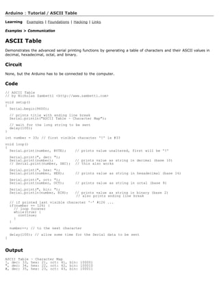


![println(Available serial ports:);
println(Serial.list());
// Uses the first port in this list (number 0). Change this to
// select the port corresponding to your Arduino board. The last
// parameter (e.g. 9600) is the speed of the communication. It
// has to correspond to the value passed to Serial.begin() in your
// Arduino sketch.
port = new Serial(this, Serial.list()[0], 9600);
// If you know the name of the port used by the Arduino board, you
// can specify it directly like this.
//port = new Serial(this, COM1, 9600);
}
void draw()
{
// draw a gradient from black to white
for (int i = 0; i 256; i++) {
stroke(i);
line(i, 0, i, 150);
}
// write the current X-position of the mouse to the serial port as
// a single byte
port.write(mouseX);
}
Restore
Edit Page | Page History | Printable View | All Recent Site Changes](https://image.slidesharecdn.com/arduino-learning-111105084504-phpapp01/85/Arduino-learning-266-320.jpg)
![Arduino : Tutorial / Dimmer
Learning Examples | Foundations | Hacking | Links
Examples Communication
Dimmer
Demonstrates the sending data from the computer to the Arduino board, in this case to control the brightness of
an LED. The data is sent in individual bytes, each of which ranges from 0 to 255. Arduino reads these bytes and
uses them to set the brightness of the LED.
Circuit
An LED connected to pin 9 (with appropriate resistor).
Code
int ledPin = 9;
void setup()
{
// begin the serial communication
Serial.begin(9600);
pinMode(ledPin, OUTPUT);
}
void loop()
{
byte val;
// check if data has been sent from the computer
if (Serial.available()) {
// read the most recent byte (which will be from 0 to 255)
val = Serial.read();
// set the brightness of the LED
analogWrite(ledPin, val);
}
}
Processing Code
// Dimmer - sends bytes over a serial port
// by David A. Mellis
import processing.serial.*;
Serial port;
void setup()
{
size(256, 150);
println(Available serial ports:);
println(Serial.list());
// Uses the first port in this list (number 0). Change this to
// select the port corresponding to your Arduino board. The last
// parameter (e.g. 9600) is the speed of the communication. It
// has to correspond to the value passed to Serial.begin() in your
// Arduino sketch.
port = new Serial(this, Serial.list()[0], 9600);
// If you know the name of the port used by the Arduino board, you
// can specify it directly like this.
//port = new Serial(this, COM1, 9600);
}
void draw()](https://image.slidesharecdn.com/arduino-learning-111105084504-phpapp01/85/Arduino-learning-267-320.jpg)
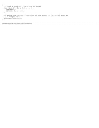

![Arduino search
Buy | Download | Getting Started | Learning | Reference | Hardware | FAQ Blog » | Forum » | Playground »
Tutorial.Graph History
Hide minor edits - Show changes to markup
March 25, 2007, at 06:14 AM by David A. Mellis -
Added lines 1-15:
Examples Communication
Graph
A simple example of communication from the Arduino board to the computer: the value of an analog input is printed. We call
this serial communication because the connection appears to both the Arduino and the computer as an old-fashioned serial
port, even though it may actually use a USB cable.
You can use the Arduino serial monitor to view the sent data, or it can be read by Processing (see code below), Flash, PD,
Max/MSP, etc.
Circuit
An analog input connected to analog input pin 0.
Code
Changed line 24 from:
Serial.print(analogRead(0) / 4, BYTE);
to:
Serial.println(analogRead(0));
Changed lines 27-28 from:
/*
to:
@]
Processing Code
[@ // Graph // by David A. Mellis // // Demonstrates reading data from the Arduino board by graphing the // values
received. // // based on Analog In // by a href=http://itp.jtnimoy.comJosh Nimoy/a.
Added lines 44-47:
String buff = ; int NEWLINE = 10;
// Store the last 64 values received so we can graph them.
Changed lines 54-56 from:
// Print a list in case COM1 doesn't work out
//println(Available serial ports:);
//printarr(PSerial.list());
to:
println(Available serial ports:);
println(Serial.list());](https://image.slidesharecdn.com/arduino-learning-111105084504-phpapp01/85/Arduino-learning-270-320.jpg)
![Changed lines 57-58 from:
//port = new Serial(this, COM1, 9600);
// Uses the first available port
to:
// Uses the first port in this list (number 0). Change this to
// select the port corresponding to your Arduino board. The last
// parameter (e.g. 9600) is the speed of the communication. It
// has to correspond to the value passed to Serial.begin() in your
// Arduino sketch.
Added lines 63-66:
// If you know the name of the port used by the Arduino board, you
// can specify it directly like this.
//port = new Serial(this, COM1, 9600);
Added line 74:
// Graph the stored values by drawing a lines between them.
Changed lines 84-87 from:
println(serial);
for (int i = 0; i 63; i++)
values[i] = values[i + 1];
to:
if (serial != NEWLINE) {
// Store all the characters on the line.
buff += char(serial);
} else {
// The end of each line is marked by two characters, a carriage
// return and a newline. We're here because we've gotten a newline,
// but we still need to strip off the carriage return.
buff = buff.substring(0, buff.length()-1);
Changed lines 93-107 from:
values[63] = serial;
to:
// Parse the String into an integer. We divide by 4 because
// analog inputs go from 0 to 1023 while colors in Processing
// only go from 0 to 255.
int val = Integer.parseInt(buff)/4;
// Clear the value of buff
buff = ;
// Shift over the existing values to make room for the new one.
for (int i = 0; i 63; i++)
values[i] = values[i + 1];
// Add the received value to the array.
values[63] = val;
}
Deleted line 108:
/
Restore
January 14, 2007, at 08:38 AM by David A. Mellis -
Added lines 1-54:
void setup()](https://image.slidesharecdn.com/arduino-learning-111105084504-phpapp01/85/Arduino-learning-271-320.jpg)
![{
Serial.begin(9600);
}
void loop()
{
Serial.print(analogRead(0) / 4, BYTE);
delay(20);
}
/*
import processing.serial.*;
Serial port;
int[] values = new int[64];
void setup()
{
size(512, 256);
// Print a list in case COM1 doesn't work out
//println(Available serial ports:);
//printarr(PSerial.list());
//port = new Serial(this, COM1, 9600);
// Uses the first available port
port = new Serial(this, Serial.list()[0], 9600);
}
void draw()
{
background(53);
stroke(255);
for (int i = 0; i 63; i++)
line(i * 8, 255 - values[i], (i + 1) * 8, 255 - values[i + 1]);
while (port.available() 0)
serialEvent(port.read());
}
void serialEvent(int serial)
{
println(serial);
for (int i = 0; i 63; i++)
values[i] = values[i + 1];
values[63] = serial;
}
*/
Restore
Edit Page | Page History | Printable View | All Recent Site Changes](https://image.slidesharecdn.com/arduino-learning-111105084504-phpapp01/85/Arduino-learning-272-320.jpg)
![Arduino : Tutorial / Graph
Learning Examples | Foundations | Hacking | Links
Examples Communication
Graph
A simple example of communication from the Arduino board to the computer: the value of an analog input is
printed. We call this serial communication because the connection appears to both the Arduino and the computer
as an old-fashioned serial port, even though it may actually use a USB cable.
You can use the Arduino serial monitor to view the sent data, or it can be read by Processing (see code below),
Flash, PD, Max/MSP, etc.
Circuit
An analog input connected to analog input pin 0.
Code
void setup()
{
Serial.begin(9600);
}
void loop()
{
Serial.println(analogRead(0));
delay(20);
}
Processing Code
// Graph
// by David A. Mellis
//
// Demonstrates reading data from the Arduino board by graphing the
// values received.
//
// based on Analog In
// by a href=http://itp.jtnimoy.comJosh Nimoy/a.
import processing.serial.*;
Serial port;
String buff = ;
int NEWLINE = 10;
// Store the last 64 values received so we can graph them.
int[] values = new int[64];
void setup()
{
size(512, 256);
println(Available serial ports:);
println(Serial.list());
// Uses the first port in this list (number 0). Change this to
// select the port corresponding to your Arduino board. The last
// parameter (e.g. 9600) is the speed of the communication. It
// has to correspond to the value passed to Serial.begin() in your
// Arduino sketch.
port = new Serial(this, Serial.list()[0], 9600);
// If you know the name of the port used by the Arduino board, you
// can specify it directly like this.](https://image.slidesharecdn.com/arduino-learning-111105084504-phpapp01/85/Arduino-learning-273-320.jpg)
![//port = new Serial(this, COM1, 9600);
}
void draw()
{
background(53);
stroke(255);
// Graph the stored values by drawing a lines between them.
for (int i = 0; i 63; i++)
line(i * 8, 255 - values[i], (i + 1) * 8, 255 - values[i + 1]);
while (port.available() 0)
serialEvent(port.read());
}
void serialEvent(int serial)
{
if (serial != NEWLINE) {
// Store all the characters on the line.
buff += char(serial);
} else {
// The end of each line is marked by two characters, a carriage
// return and a newline. We're here because we've gotten a newline,
// but we still need to strip off the carriage return.
buff = buff.substring(0, buff.length()-1);
// Parse the String into an integer. We divide by 4 because
// analog inputs go from 0 to 1023 while colors in Processing
// only go from 0 to 255.
int val = Integer.parseInt(buff)/4;
// Clear the value of buff
buff = ;
// Shift over the existing values to make room for the new one.
for (int i = 0; i 63; i++)
values[i] = values[i + 1];
// Add the received value to the array.
values[63] = val;
}
}
(Printable View of http://www.arduino.cc/en/Tutorial/Graph)](https://image.slidesharecdn.com/arduino-learning-111105084504-phpapp01/85/Arduino-learning-274-320.jpg)

![import processing.serial.*;
Serial port;
void setup()
{
size(200, 200);
noStroke();
frameRate(10);
// List all the available serial ports in the output pane.
// You will need to choose the port that the Arduino board is
// connected to from this list. The first port in the list is
// port #0 and the third port in the list is port #2.
println(Serial.list());
// Open the port that the Arduino board is connected to (in this case #0)
// Make sure to open the port at the same speed Arduino is using (9600bps)
port = new Serial(this, Serial.list()[0], 9600);
}
// function to test if mouse is over square
boolean mouseOverRect()
{
return ((mouseX = 50)(mouseX = 150)(mouseY = 50)(mouseY = 150));
}
void draw()
{
background(#222222);
if(mouseOverRect()) // if mouse is over square
{
fill(#BBBBB0); // change color
port.write('H'); // send an 'H' to indicate mouse is over square
} else {
fill(#666660); // change color
port.write('L'); // send an 'L' otherwise
}
rect(50, 50, 100, 100); // draw square
}
Restore
Edit Page | Page History | Printable View | All Recent Site Changes](https://image.slidesharecdn.com/arduino-learning-111105084504-phpapp01/85/Arduino-learning-277-320.jpg)
![// Open the port that the Arduino board is connected to (in this case #0)
// Make sure to open the port at the same speed Arduino is using (9600bps)
port = new Serial(this, Serial.list()[0], 9600);
}
// function to test if mouse is over square
boolean mouseOverRect()
{
return ((mouseX = 50)(mouseX = 150)(mouseY = 50)(mouseY = 150));
}
void draw()
{
background(#222222);
if(mouseOverRect()) // if mouse is over square
{
fill(#BBBBB0); // change color
port.write('H'); // send an 'H' to indicate mouse is over square
} else {
fill(#666660); // change color
port.write('L'); // send an 'L' otherwise
}
rect(50, 50, 100, 100); // draw square
}
(Printable View of http://www.arduino.cc/en/Tutorial/PhysicalPixel)](https://image.slidesharecdn.com/arduino-learning-111105084504-phpapp01/85/Arduino-learning-279-320.jpg)

![Arduino search
Buy | Download | Getting Started | Learning | Reference | Hardware | FAQ Blog » | Forum » | Playground »
Tutorial.VirtualColorMixer History
Hide minor edits - Show changes to markup
March 26, 2007, at 07:39 AM by David A. Mellis -
Added lines 1-12:
Examples Communication
Virtual Color Mixer
Demonstrates one technique for sending multiple values from the Arduino board to the computer. In this case, the readings
from three potentiometers are used to set the red, green, and blue components of the background color of a Processing
sketch.
Circuit
Potentiometers connected to analog input pins 0, 1, and 2.
Code
Changed lines 33-37 from:
to:
@]
Processing Code
[@
Deleted line 50:
/*
Deleted line 105:
/
Restore
January 14, 2007, at 08:30 AM by David A. Mellis -
Added lines 1-92:
int redPin = 0;
int greenPin = 1;
int bluePin = 2;
void setup()
{
Serial.begin(9600);
}
void loop()
{
Serial.print(R);
Serial.println(analogRead(redPin));
Serial.print(G);
Serial.println(analogRead(greenPin));
Serial.print(B);
Serial.println(analogRead(bluePin));](https://image.slidesharecdn.com/arduino-learning-111105084504-phpapp01/85/Arduino-learning-281-320.jpg)
![delay(100);
}
/**
* Color Mixer
* by David A. Mellis
*
* Created 2 December 2006
*
* based on Analog In
* by a href=http://itp.jtnimoy.comJosh Nimoy/a.
*
* Created 8 February 2003
* Updated 2 April 2005
*/
/*
import processing.serial.*;
String buff = ;
int rval = 0, gval = 0, bval = 0;
int NEWLINE = 10;
Serial port;
void setup()
{
size(200, 200);
// Print a list in case COM1 doesn't work out
println(Available serial ports:);
println(Serial.list());
//port = new Serial(this, COM1, 9600);
// Uses the first available port
port = new Serial(this, Serial.list()[0], 9600);
}
void draw()
{
while (port.available() 0) {
serialEvent(port.read());
}
background(rval, gval, bval);
}
void serialEvent(int serial)
{
// If the variable serial is not equal to the value for
// a new line, add the value to the variable buff. If the
// value serial is equal to the value for a new line,
// save the value of the buffer into the variable val.
if(serial != NEWLINE) {
buff += char(serial);
} else {
// The first character tells us which color this value is for
char c = buff.charAt(0);
// Remove it from the string
buff = buff.substring(1);
// Discard the carriage return at the end of the buffer
buff = buff.substring(0, buff.length()-1);
// Parse the String into an integer
if (c == 'R')
rval = Integer.parseInt(buff);
else if (c == 'G')](https://image.slidesharecdn.com/arduino-learning-111105084504-phpapp01/85/Arduino-learning-282-320.jpg)

![//port = new Serial(this, COM1, 9600);
// Uses the first available port
port = new Serial(this, Serial.list()[0], 9600);
}
void draw()
{
while (port.available() 0) {
serialEvent(port.read());
}
background(rval, gval, bval);
}
void serialEvent(int serial)
{
// If the variable serial is not equal to the value for
// a new line, add the value to the variable buff. If the
// value serial is equal to the value for a new line,
// save the value of the buffer into the variable val.
if(serial != NEWLINE) {
buff += char(serial);
} else {
// The first character tells us which color this value is for
char c = buff.charAt(0);
// Remove it from the string
buff = buff.substring(1);
// Discard the carriage return at the end of the buffer
buff = buff.substring(0, buff.length()-1);
// Parse the String into an integer
if (c == 'R')
rval = Integer.parseInt(buff);
else if (c == 'G')
gval = Integer.parseInt(buff);
else if (c == 'B')
bval = Integer.parseInt(buff);
// Clear the value of buff
buff = ;
}
}
(Printable View of http://www.arduino.cc/en/Tutorial/VirtualColorMixer)](https://image.slidesharecdn.com/arduino-learning-111105084504-phpapp01/85/Arduino-learning-285-320.jpg)

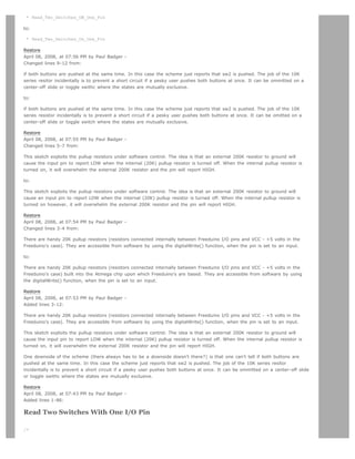
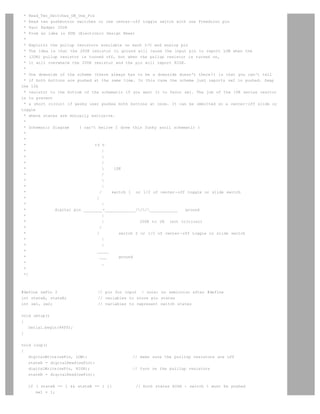
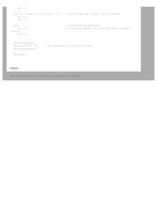
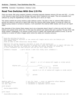

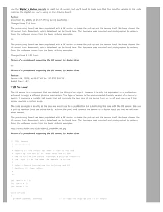

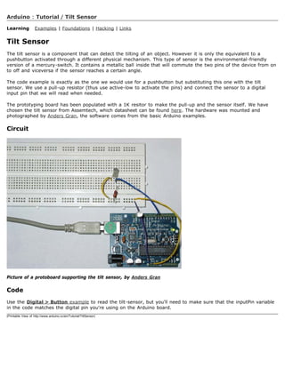

![Arduino search
Buy | Download | Getting Started | Learning | Reference | Hardware | FAQ Blog » | Forum » | Playground »
Tutorial.ControleLEDcircleWithJoystick History
Hide minor edits - Show changes to markup
February 03, 2006, at 10:31 AM by 193.49.124.107 -
Added lines 1-163:
Controlling a circle of LEDs with a Joystick
The whole circuit:
http://static.flickr.com/35/94946013_ba47fe116e.jpg
Detail of the LED wiring
http://static.flickr.com/39/94946015_aaab0281e8.jpg
Detail of the arduino wiring
http://static.flickr.com/42/94946020_2a1dd30b97.jpg
How this works
As you know from the Interfacing a Joystick tutorial, the joystick gives a coordinate (x,y) back to arduino. As you can see
looking to the joystick is that the space in which he moves is a circle. This circle will be from now on our 'Pie' (see bottom
right of the first image).
The only thing we need now to understand is that we have divided our Pie in 8 pieces. To each piece will correspond an LED.
(See figure below). This way, when the joystick gives us a coordinate, it will necesarilly belong to one of the pies. Then, the
program always lights up the LED corresponding to the pie in which the joystick is.
http://static.flickr.com/19/94946024_f7fd4b55ec.jpg
Code
/* Controle_LEDcirle_with_joystik
* ------------
* This program controles a cirle of 8 LEDs through a joystick
*
* First it reads two analog pins that are connected
* to a joystick made of two potentiometers
*
* This input is interpreted as a coordinate (x,y)
*
* The program then calculates to which of the 8
* possible zones belogns the coordinate (x,y)
*
* Finally it ligths up the LED which is placed in the
* detected zone
*
* @authors: Cristina Hoffmann and Gustavo Jose Valera
* @hardware: Cristina Hofmann and Gustavo Jose Valera
* @context: Arduino Workshop at medialamadrid
*/
// Declaration of Variables
int ledPins [] = { 2,3,4,5,6,7,8,9 }; // Array of 8 leds mounted in a circle
int ledVerde = 13;](https://image.slidesharecdn.com/arduino-learning-111105084504-phpapp01/85/Arduino-learning-299-320.jpg)
![int espera = 40; // Time you should wait for turning on the leds
int joyPin1 = 0; // slider variable connecetd to analog pin 0
int joyPin2 = 1; // slider variable connecetd to analog pin 1
int coordX = 0; // variable to read the value from the analog pin 0
int coordY = 0; // variable to read the value from the analog pin 1
int centerX = 500; // we measured the value for the center of the joystick
int centerY = 500;
int actualZone = 0;
int previousZone = 0;
// Asignment of the pins
void setup()
{
int i;
beginSerial(9600);
pinMode (ledVerde, OUTPUT);
for (i=0; i 8; i++)
{
pinMode(ledPins[i], OUTPUT);
}
}
// function that calculates the slope of the line that passes through the points
// x1, y1 and x2, y2
int calculateSlope(int x1, int y1, int x2, int y2)
{
return ((y1-y2) / (x1-x2));
}
// function that calculates in which of the 8 possible zones is the coordinate x y, given the center cx,
cy
int calculateZone (int x, int y, int cx, int cy)
{
int alpha = calculateSlope(x,y, cx,cy); // slope of the segment betweent the point and the center
if (x cx)
{
if (y cy) // first cuadrant
{
if (alpha 1) // The slope is 1, thus higher part of the first quadrant
return 0;
else
return 1; // Otherwise the point is in the lower part of the first quadrant
}
else // second cuadrant
{
if (alpha -1)
return 2;
else
return 3;
}
}
else
{
if (y cy) // third cuadrant
{
if (alpha 1)
return 4;
else
return 5;
}
else // fourth cuadrant
{
if (alpha -1)
return 6;](https://image.slidesharecdn.com/arduino-learning-111105084504-phpapp01/85/Arduino-learning-300-320.jpg)
![else
return 7;
}
}
}
void loop() {
digitalWrite(ledVerde, HIGH); // flag to know we entered the loop, you can erase this if you want
// reads the value of the variable resistors
coordX = analogRead(joyPin1);
coordY = analogRead(joyPin2);
// We calculate in which x
actualZone = calculateZone(coordX, coordY, centerX, centerY);
digitalWrite (ledPins[actualZone], HIGH);
if (actualZone != previousZone)
digitalWrite (ledPins[previousZone], LOW);
// we print int the terminal, the cartesian value of the coordinate, and the zone where it belongs.
//This is not necesary for a standalone version
serialWrite('C');
serialWrite(32); // print space
printInteger(coordX);
serialWrite(32); // print space
printInteger(coordY);
serialWrite(10);
serialWrite(13);
serialWrite('Z');
serialWrite(32); // print space
printInteger(actualZone);
serialWrite(10);
serialWrite(13);
// But this is necesary so, don't delete it!
previousZone = actualZone;
// delay (500);
}
@idea: Cristina Hoffmann and Gustavo Jose Valera
@code: Cristina Hoffmann and Gustavo Jose Valera
@pictures and graphics: Cristina Hoffmann
@date: 20051008 - Madrid - Spain
Restore
Edit Page | Page History | Printable View | All Recent Site Changes](https://image.slidesharecdn.com/arduino-learning-111105084504-phpapp01/85/Arduino-learning-301-320.jpg)
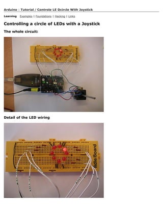
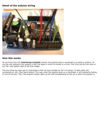
![Code
/* Controle_LEDcirle_with_joystik
* ------------
* This program controles a cirle of 8 LEDs through a joystick
*
* First it reads two analog pins that are connected
* to a joystick made of two potentiometers
*
* This input is interpreted as a coordinate (x,y)
*
* The program then calculates to which of the 8
* possible zones belogns the coordinate (x,y)
*
* Finally it ligths up the LED which is placed in the
* detected zone
*
* @authors: Cristina Hoffmann and Gustavo Jose Valera
* @hardware: Cristina Hofmann and Gustavo Jose Valera
* @context: Arduino Workshop at medialamadrid
*/
// Declaration of Variables
int ledPins [] = { 2,3,4,5,6,7,8,9 }; // Array of 8 leds mounted in a circle
int ledVerde = 13;
int espera = 40; // Time you should wait for turning on the leds
int joyPin1 = 0; // slider variable connecetd to analog pin 0
int joyPin2 = 1; // slider variable connecetd to analog pin 1
int coordX = 0; // variable to read the value from the analog pin 0
int coordY = 0; // variable to read the value from the analog pin 1
int centerX = 500; // we measured the value for the center of the joystick
int centerY = 500;
int actualZone = 0;
int previousZone = 0;](https://image.slidesharecdn.com/arduino-learning-111105084504-phpapp01/85/Arduino-learning-304-320.jpg)
![// Asignment of the pins
void setup()
{
int i;
beginSerial(9600);
pinMode (ledVerde, OUTPUT);
for (i=0; i 8; i++)
{
pinMode(ledPins[i], OUTPUT);
}
}
// function that calculates the slope of the line that passes through the points
// x1, y1 and x2, y2
int calculateSlope(int x1, int y1, int x2, int y2)
{
return ((y1-y2) / (x1-x2));
}
// function that calculates in which of the 8 possible zones is the coordinate x y, given the
center cx, cy
int calculateZone (int x, int y, int cx, int cy)
{
int alpha = calculateSlope(x,y, cx,cy); // slope of the segment betweent the point and the
center
if (x cx)
{
if (y cy) // first cuadrant
{
if (alpha 1) // The slope is 1, thus higher part of the first quadrant
return 0;
else
return 1; // Otherwise the point is in the lower part of the first quadrant
}
else // second cuadrant
{
if (alpha -1)
return 2;
else
return 3;
}
}
else
{
if (y cy) // third cuadrant
{
if (alpha 1)
return 4;
else
return 5;
}
else // fourth cuadrant
{
if (alpha -1)
return 6;
else
return 7;
}
}
}
void loop() {
digitalWrite(ledVerde, HIGH); // flag to know we entered the loop, you can erase this if you
want
// reads the value of the variable resistors
coordX = analogRead(joyPin1);
coordY = analogRead(joyPin2);
// We calculate in which x
actualZone = calculateZone(coordX, coordY, centerX, centerY);
digitalWrite (ledPins[actualZone], HIGH);](https://image.slidesharecdn.com/arduino-learning-111105084504-phpapp01/85/Arduino-learning-305-320.jpg)
![if (actualZone != previousZone)
digitalWrite (ledPins[previousZone], LOW);
// we print int the terminal, the cartesian value of the coordinate, and the zone where it
belongs.
//This is not necesary for a standalone version
serialWrite('C');
serialWrite(32); // print space
printInteger(coordX);
serialWrite(32); // print space
printInteger(coordY);
serialWrite(10);
serialWrite(13);
serialWrite('Z');
serialWrite(32); // print space
printInteger(actualZone);
serialWrite(10);
serialWrite(13);
// But this is necesary so, don't delete it!
previousZone = actualZone;
// delay (500);
}
@idea: Cristina Hoffmann and Gustavo Jose Valera
@code: Cristina Hoffmann and Gustavo Jose Valera
@pictures and graphics: Cristina Hoffmann
@date: 20051008 - Madrid - Spain
(Printable View of http://www.arduino.cc/en/Tutorial/ControleLEDcircleWithJoystick)](https://image.slidesharecdn.com/arduino-learning-111105084504-phpapp01/85/Arduino-learning-306-320.jpg)

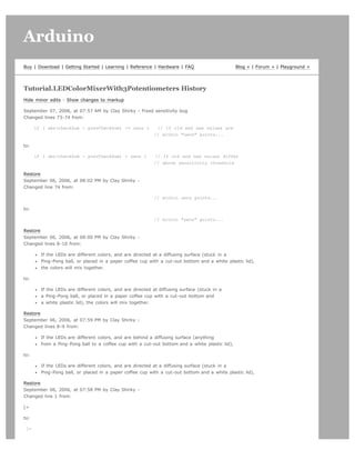
![Added line 105:
=]
Restore
September 06, 2006, at 07:56 PM by Clay Shirky -
Added line 1:
[=
Changed line 3 from:
Espresso-cup Color Mixer:
to:
Coffee-cup Color Mixer:
Changed lines 9-10 from:
from a Ping-Pong ball to a coffee cup with a white plastic lid), the colors
will mix together.
to:
from a Ping-Pong ball to a coffee cup with a cut-out bottom and a white plastic lid),
the colors will mix together.
Restore
September 06, 2006, at 07:53 PM by Clay Shirky -
Added lines 1-103:
/*
Espresso-cup Color Mixer:
Code for mixing and reporting PWM-mediated color
Assumes Arduino 0004 or higher, as it uses Serial.begin()-style communication
Control 3 LEDs with 3 potentiometers
If the LEDs are different colors, and are behind a diffusing surface (anything
from a Ping-Pong ball to a coffee cup with a white plastic lid), the colors
will mix together.
When you mix a color you like, stop adjusting the pots.
The mix values that create that color will be reported via serial out.
Standard colors for light mixing are Red, Green, and Blue, though you can mix
with any three colors; Red + Blue + White would let you mix shades of red,
blue, and purple (though no yellow, orange, green, or blue-green.)
Put 220 Ohm resistors in line with pots, to prevent circuit from
grounding out when the pots are at zero
/
// Analog pin settings int aIn = 0; // Potentiometers connected to analog pins 0, 1, and 2 int bIn = 1; // (Connect power to
5V and ground to analog ground) int cIn = 2;
// Digital pin settings int aOut = 9; // LEDs connected to digital pins 9, 10 and 11 int bOut = 10; // (Connect cathodes to
digital ground) int cOut = 11;
// Values int aVal = 0; // Variables to store the input from the potentiometers int bVal = 0; int cVal = 0;
// Variables for comparing values between loops int i = 0; // Loop counter int wait = (1000); // Delay between most recent
pot adjustment and output
int checkSum = 0; // Aggregate pot values int prevCheckSum = 0; int sens = 3; // Sensitivity theshold, to prevent small
changes in
// pot values from triggering false reporting
// FLAGS int PRINT = 1; // Set to 1 to output values int DEBUG = 1; // Set to 1 to turn on debugging output](https://image.slidesharecdn.com/arduino-learning-111105084504-phpapp01/85/Arduino-learning-309-320.jpg)
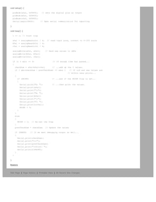


![Changed line 64 from:
to:
Restore
July 02, 2008, at 01:49 PM by David A. Mellis -
Changed lines 58-66 from:
@]
to:
@]
Data
Here are some accelerometer readings from the y-axis of an ADXL322 2g accelerometer. Values should be the same for the
other axes, but will vary based on the sensitivity of the device.
Angle -90 -80 -70 -60 -50 -40 -30 -20 -10 0 10 20 30 40 50 60 70 80 90
Acceleration 662 660 654 642 628 610 589 563 537 510 485 455 433 408 390 374 363 357 355
Restore
July 02, 2008, at 01:43 PM by David A. Mellis -
Changed line 21 from:
to:
Restore
July 02, 2008, at 01:43 PM by David A. Mellis -
Changed line 15 from:
to:
Restore
July 02, 2008, at 01:42 PM by David A. Mellis -
Added lines 13-14:
Pinout for the above configuration:
Added lines 19-20:
Or, if you're using just the accelerometer:
Restore
July 02, 2008, at 01:41 PM by David A. Mellis -
Changed line 13 from:
to:
Changed line 17 from:
to:
Restore
July 02, 2008, at 01:40 PM by David A. Mellis -
Changed line 13 from:
to:
Changed line 17 from:
to:
Restore
July 02, 2008, at 01:40 PM by David A. Mellis -
Changed line 17 from:
to:
Restore
July 02, 2008, at 01:40 PM by David A. Mellis -
Changed line 13 from:
to:
Restore
July 02, 2008, at 01:40 PM by David A. Mellis -
Added lines 11-12:
An ADXL322 on a Sparkfun breakout board inserted into the analog input pins of an Arduino.
Changed lines 14-21 from:
Accelerometer Pin Arduino Pin
Self-Test Analog Input 0
Z-Axis Analog Input 1](https://image.slidesharecdn.com/arduino-learning-111105084504-phpapp01/85/Arduino-learning-321-320.jpg)

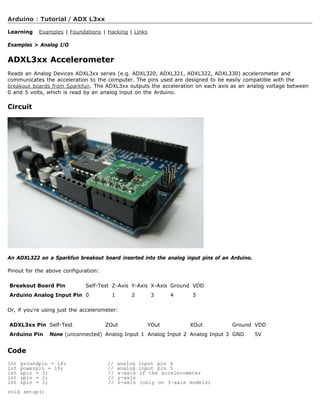
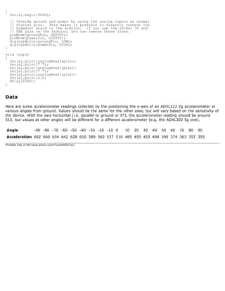

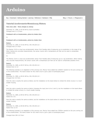
![=]
to:
=]
http://static.flickr.com/28/65531406_d7150f954a.jpg
Accelerometer mounted on prototyping board, by M. Yarza
The following example is an adaptation of the previous one. Marcos Yarza added two 220Ohm resistors to the pins coming out
of the accelerometer. The board chosen for this small circuit is just a piece of prototyping board.
Restore
November 21, 2005, at 07:32 AM by 195.178.229.112 -
Changed lines 7-8 from:
The example shown here was mounted by Anders Grant, while the software was created by Marcos Yarza, who is Arduino's
accelerometer technology researcher, at the University of Zaragoza, Spain. The board is connected minimally, only the two
axis pins are plugged to the board, leaving the temperature pin open.
to:
The example shown here was mounted by Anders Gran, while the software was created by Marcos Yarza, who is Arduino's
accelerometer technology researcher, at the University of Zaragoza, Spain. The board is connected minimally, only the two
axis pins are plugged to the board, leaving the temperature pin open.
Changed lines 11-12 from:
Protoboard with an Accelerometer, picture by Anders Grant
to:
Protoboard with an Accelerometer, picture by Anders Gran
Restore
November 21, 2005, at 07:31 AM by 195.178.229.112 -
Changed lines 7-8 from:
The example shown here was mounted by Anders Grant, while the software was created by Marcos Yarza, who is Arduino's
accelerometer technology researcher, at the University of Zaragoza, Spain. The board is connected minimally, only the two
axis are plugged to the board, leaving the temperature pin open.
to:
The example shown here was mounted by Anders Grant, while the software was created by Marcos Yarza, who is Arduino's
accelerometer technology researcher, at the University of Zaragoza, Spain. The board is connected minimally, only the two
axis pins are plugged to the board, leaving the temperature pin open.
Restore
November 21, 2005, at 07:30 AM by 195.178.229.112 -
Changed line 89 from:
serialWrite('X');
to:
printByte('X');
Changed line 92 from:
serialWrite('Y');
to:
printByte('Y');
Changed line 94 from:
serialWrite(sign);
to:
printByte(sign);](https://image.slidesharecdn.com/arduino-learning-111105084504-phpapp01/85/Arduino-learning-329-320.jpg)
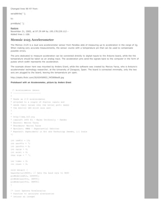
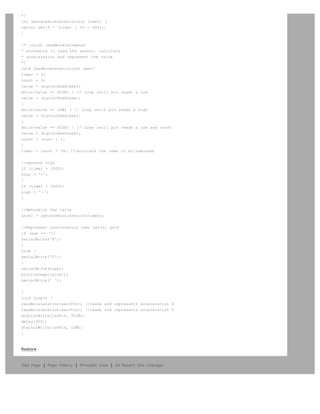
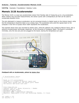
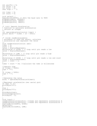
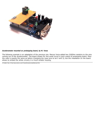

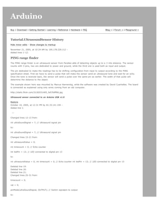
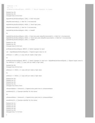
![to:
}
Deleted line 73:
Deleted line 74:
Changed lines 78-79 from:
}
to:
}
=]
Restore
October 08, 2005, at 03:58 AM by 62.97.121.93 -
Added lines 1-114:
/* Ultrasound Sensor
*------------------
*
* Reads values (00014-01199) from an ultrasound sensor (3m sensor)
* and writes the values to the serialport.
*
* http://www.xlab.se | http://www.0j0.org
* copyleft 2005 Mackie for XLAB | DojoDave for DojoCorp
*
*/
int ultraSoundSignal = 7; // Ultrasound signal pin
int val = 0;
int ultrasoundValue = 0;
int timecount = 0; // Echo counter
int ledPin = 13; // LED connected to digital pin 13
void setup() {
beginSerial(9600); // Sets the baud rate to 9600
pinMode(ledPin, OUTPUT); // Sets the digital pin as output
}
void loop() {
timecount = 0;
val = 0;
pinMode(ultraSoundSignal, OUTPUT); // Switch signalpin to output
/* Send low-high-low pulse to activate the trigger pulse of the sensor
* -------------------------------------------------------------------
*/
digitalWrite(ultraSoundSignal, LOW); // Send low pulse
delayMicroseconds(2); // Wait for 2 microseconds
digitalWrite(ultraSoundSignal, HIGH); // Send high pulse
delayMicroseconds(5); // Wait for 5 microseconds
digitalWrite(ultraSoundSignal, LOW); // Holdoff
/* Listening for echo pulse](https://image.slidesharecdn.com/arduino-learning-111105084504-phpapp01/85/Arduino-learning-338-320.jpg)
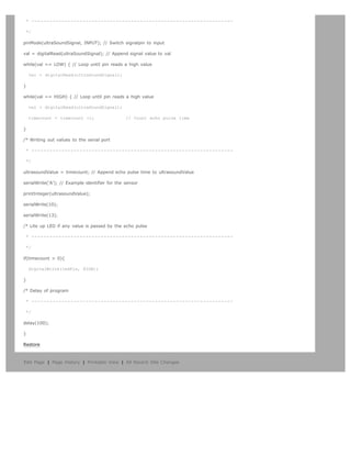

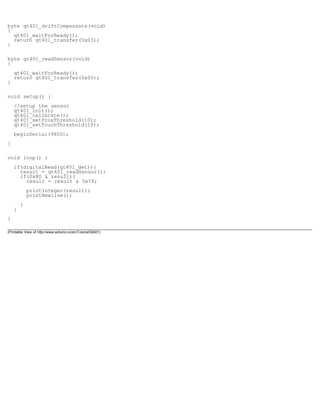

![Arduino search
Buy | Download | Getting Started | Learning | Reference | Hardware | FAQ Blog » | Forum » | Playground »
Tutorial.PlayMelody History
Hide minor edits - Show changes to markup
October 02, 2006, at 04:15 PM by Clay Shirky -
Changed line 169 from:
[=
to:
[=
Restore
October 02, 2006, at 04:15 PM by Clay Shirky -
Added lines 165-234:
=]
Second version, with volume control set using analogWrite()
[= /* Play Melody
* -----------
*
* Program to play melodies stored in an array, it requires to know
* about timing issues and about how to play tones.
*
* The calculation of the tones is made following the mathematical
* operation:
*
* timeHigh = 1/(2 * toneFrequency) = period / 2
*
* where the different tones are described as in the table:
*
* note frequency period PW (timeHigh)
* c 261 Hz 3830 1915
* d 294 Hz 3400 1700
* e 329 Hz 3038 1519
* f 349 Hz 2864 1432
* g 392 Hz 2550 1275
* a 440 Hz 2272 1136
* b 493 Hz 2028 1014
* C 523 Hz 1912 956
*
* (cleft) 2005 D. Cuartielles for K3
*/
int ledPin = 13; int speakerOut = 9; byte names[] = {'c', 'd', 'e', 'f', 'g', 'a', 'b', 'C'}; int tones[] = {1915, 1700, 1519,
1432, 1275, 1136, 1014, 956}; byte melody[] = 2d2a1f2c2d2a2d2c2f2d2a2c2d2a1f2c2d2a2a2g2p8p8p8p; // count length:
1 2 3 4 5 6 7 8 9 0 1 2 3 4 5 6 7 8 9 0 1 2 3 4 5 6 7 8 9 0 // 10 20 30 int count = 0; int count2 = 0; int count3 = 0; int
MAX_COUNT = 24; int statePin = LOW;
void setup() {
pinMode(ledPin, OUTPUT);
}](https://image.slidesharecdn.com/arduino-learning-111105084504-phpapp01/85/Arduino-learning-351-320.jpg)
![void loop() {
analogWrite(speakerOut, 0);
for (count = 0; count MAX_COUNT; count++) {
statePin = !statePin;
digitalWrite(ledPin, statePin);
for (count3 = 0; count3 = (melody[count*2] - 48) * 30; count3++) {
for (count2=0;count28;count2++) {
if (names[count2] == melody[count*2 + 1]) {
analogWrite(speakerOut,500);
delayMicroseconds(tones[count2]);
analogWrite(speakerOut, 0);
delayMicroseconds(tones[count2]);
}
if (melody[count*2 + 1] == 'p') {
// make a pause of a certain size
analogWrite(speakerOut, 0);
delayMicroseconds(500);
}
}
}
}
}
Restore
October 02, 2006, at 04:10 PM by Clay Shirky - Re-wrote Example #1
Changed lines 21-22 from:
* Program to play melodies stored in an array, it requires to know
* about timing issues and about how to play tones.
to:
* Program to play a simple melody
Changed lines 23-24 from:
* The calculation of the tones is made following the mathematical
* operation:
to:
* Tones are created by quickly pulsing a speaker on and off
* using PWM, to create signature frequencies.
Changed lines 26-33 from:
* timeHigh = 1/(2 * toneFrequency) = period / 2
to:
* Each note has a frequency, created by varying the period of
* vibration, measured in microseconds. We'll use pulse-width
* modulation (PWM) to create that vibration.
* We calculate the pulse-width to be half the period; we pulse
* the speaker HIGH for 'pulse-width' microseconds, then LOW
* for 'pulse-width' microseconds.
* This pulsing creates a vibration of the desired frequency.
Deleted lines 34-45:
* where the different tones are described as in the table:
*
* note frequency period PW (timeHigh)
* c 261 Hz 3830 1915
* d 294 Hz 3400 1700
* e 329 Hz 3038 1519
* f 349 Hz 2864 1432](https://image.slidesharecdn.com/arduino-learning-111105084504-phpapp01/85/Arduino-learning-352-320.jpg)
![* g 392 Hz 2550 1275
* a 440 Hz 2272 1136
* b 493 Hz 2028 1014
* C 523 Hz 1912 956
*
Added lines 36-37:
* Refactoring and comments 2006 clay.shirky@nyu.edu
* See NOTES in comments at end for possible improvements
Changed lines 40-55 from:
int ledPin = 13; int speakerOut = 9; byte names[] = {'c', 'd', 'e', 'f', 'g', 'a', 'b', 'C'}; int tones[] = {1915, 1700, 1519,
1432, 1275, 1136, 1014, 956}; byte melody[] = 2d2a1f2c2d2a2d2c2f2d2a2c2d2a1f2c2d2a2a2g2p8p8p8p; // count length:
1 2 3 4 5 6 7 8 9 0 1 2 3 4 5 6 7 8 9 0 1 2 3 4 5 6 7 8 9 0 // 10 20 30 int count = 0; int count2 = 0; int count3 = 0; int
MAX_COUNT = 24; int statePin = LOW;
void setup() {
pinMode(ledPin, OUTPUT);
pinMode(speakerOut, OUTPUT);
to:
// TONES ========================================== // Start by defining the relationship between //
note, period, frequency.
1. define c 3830 // 261 Hz
2. define d 3400 // 294 Hz
3. define e 3038 // 329 Hz
4. define f 2864 // 349 Hz
5. define g 2550 // 392 Hz
6. define a 2272 // 440 Hz
7. define b 2028 // 493 Hz
8. define C 1912 // 523 Hz
// Define a special note, 'R', to represent a rest
1. define R 0
// SETUP ============================================ // Set up speaker on a PWM pin (digital 9, 10
or 11) int speakerOut = 9; // Do we want debugging on serial out? 1 for yes, 0 for no int DEBUG = 1;
void setup() {
pinMode(speakerOut, OUTPUT);
if (DEBUG) {
Serial.begin(9600); // Set serial out if we want debugging
}
Added lines 67-112:
// MELODY and TIMING ======================================= // melody[] is an array of notes,
accompanied by beats[], // which sets each note's relative length (higher #, longer note) int melody[] = { C, b, g, C, b, e, R,
C, c, g, a, C }; int beats[] = { 16, 16, 16, 8, 8, 16, 32, 16, 16, 16, 8, 8 }; int MAX_COUNT = sizeof(melody) / 2; // Melody
length, for looping.
// Set overall tempo long tempo = 10000; // Set length of pause between notes int pause = 1000; // Loop variable to
increase Rest length int rest_count = 100; //-BLETCHEROUS HACK; See NOTES
// Initialize core variables int tone = 0; int beat = 0; long duration = 0;
// PLAY TONE ============================================== // Pulse the speaker to play a tone for
a particular duration void playTone() {
long elapsed_time = 0;
if (tone 0) { // if this isn't a Rest beat, while the tone has
// played less long than 'duration', pulse speaker HIGH and LOW
while (elapsed_time duration) {
digitalWrite(speakerOut,HIGH);](https://image.slidesharecdn.com/arduino-learning-111105084504-phpapp01/85/Arduino-learning-353-320.jpg)
![delayMicroseconds(tone / 2);
// DOWN
digitalWrite(speakerOut, LOW);
delayMicroseconds(tone / 2);
// Keep track of how long we pulsed
elapsed_time += (tone);
}
}
else { // Rest beat; loop times delay
for (int j = 0; j rest_count; j++) { // See NOTE on rest_count
delayMicroseconds(duration);
}
}
}
// LET THE WILD RUMPUS BEGIN =============================
Changed lines 114-131 from:
digitalWrite(speakerOut, LOW);
for (count = 0; count MAX_COUNT; count++) {
statePin = !statePin;
digitalWrite(ledPin, statePin);
for (count3 = 0; count3 = (melody[count*2] - 48) * 30; count3++) {
for (count2=0;count28;count2++) {
if (names[count2] == melody[count*2 + 1]) {
digitalWrite(speakerOut,HIGH);
delayMicroseconds(tones[count2]);
digitalWrite(speakerOut, LOW);
delayMicroseconds(tones[count2]);
}
if (melody[count*2 + 1] == 'p') {
// make a pause of a certain size
digitalWrite(speakerOut, 0);
delayMicroseconds(500);
}
}
to:
// Set up a counter to pull from melody[] and beats[]
for (int i=0; iMAX_COUNT; i++) {
tone = melody[i];
beat = beats[i];
duration = beat * tempo; // Set up timing
playTone();
// A pause between notes...
delayMicroseconds(pause);
if (DEBUG) { // If debugging, report loop, tone, beat, and duration
Serial.print(i);
Serial.print(:);
Serial.print(beat);
Serial.print( );
Serial.print(tone);
Serial.print( );
Serial.println(duration);
Changed lines 137-166 from:
=]
Example 2: Play Melody _ faded volume](https://image.slidesharecdn.com/arduino-learning-111105084504-phpapp01/85/Arduino-learning-354-320.jpg)
![[=
/* Play Melody - FV
* ----------------
*
* Program to play melodies stored in an array, it requires to know
* about timing issues and about how to play tones.
*
* The calculation of the tones is made following the mathematical
* operation:
*
* timeHigh = 1/(2 * toneFrequency) = period / 2
*
* where the different tones are described as in the table:
*
* note frequency period PW (timeHigh)
* c 261 Hz 3830 1915
* d 294 Hz 3400 1700
* e 329 Hz 3038 1519
* f 349 Hz 2864 1432
* g 392 Hz 2550 1275
* a 440 Hz 2272 1136
* b 493 Hz 2028 1014
* C 523 Hz 1912 956
*
* We use the Pulse Width feature with analogWrite to change volume
*
* (cleft) 2005 D. Cuartielles for K3
to:
/*
* NOTES
* The program purports to hold a tone for 'duration' microseconds.
* Lies lies lies! It holds for at least 'duration' microseconds, _plus_
* any overhead created by incremeting elapsed_time (could be in excess of
* 3K microseconds) _plus_ overhead of looping and two digitalWrites()
*
* As a result, a tone of 'duration' plays much more slowly than a rest
* of 'duration.' rest_count creates a loop variable to bring 'rest' beats
* in line with 'tone' beats of the same length.
*
* rest_count will be affected by chip architecture and speed, as well as
* overhead from any program mods. Past behavior is no guarantee of future
* performance. Your mileage may vary. Light fuse and get away.
*
* This could use a number of enhancements:
* ADD code to let the programmer specify how many times the melody should
* loop before stopping
* ADD another octave
* MOVE tempo, pause, and rest_count to #define statements
* RE-WRITE to include volume, using analogWrite, as with the second program at
* http://www.arduino.cc/en/Tutorial/PlayMelody
* ADD code to make the tempo settable by pot or other input device
* ADD code to take tempo or volume settable by serial communication
* (Requires 0005 or higher.)
* ADD code to create a tone offset (higer or lower) through pot etc
* REPLACE random melody with opening bars to 'Smoke on the Water'
Deleted lines 164-205:
int ledPin = 13; int speakerOut = 9; int volume = 300; // maximum volume is 1000 byte names[] = {'c', 'd', 'e', 'f', 'g', 'a',
'b', 'C'}; int tones[] = {1915, 1700, 1519, 1432, 1275, 1136, 1014, 956}; byte melody[] =
2d2a1f2c2d2a2d2c2f2d2a2c2d2a1f2c2d2a2a2g2p8p8p8p; // count length: 1 2 3 4 5 6 7 8 9 0 1 2 3 4 5 6 7 8 9 0 1 2 3 4
5 6 7 8 9 0 // 10 20 30 int count = 0; int count2 = 0; int count3 = 0; int MAX_COUNT = 24; int statePin = LOW;](https://image.slidesharecdn.com/arduino-learning-111105084504-phpapp01/85/Arduino-learning-355-320.jpg)
![void setup() {
pinMode(ledPin, OUTPUT);
}
void loop() {
analogWrite(speakerOut, 0);
for (count = 0; count MAX_COUNT; count++) {
statePin = !statePin;
digitalWrite(ledPin, statePin);
for (count3 = 0; count3 = (melody[count*2] - 48) * 30; count3++) {
for (count2=0;count28;count2++) {
if (names[count2] == melody[count*2 + 1]) {
analogWrite(speakerOut,volume);
delayMicroseconds(tones[count2]);
analogWrite(speakerOut, 0);
delayMicroseconds(tones[count2]);
}
if (melody[count*2 + 1] == 'p') {
// make a pause of a certain size
analogWrite(speakerOut, 0);
delayMicroseconds(500);
}
}
}
}
}
Restore
October 18, 2005, at 01:50 AM by 195.178.229.25 -
Changed lines 5-6 from:
A Piezo is nothing but an electronic device that can both be used to play tones and to detect tones. In our example we are
plugging the Piezo on the pin number 10, that supports the functionality of writing a PWM signal to it, and not just a plain
HIGH or LOW value.
to:
A Piezo is nothing but an electronic device that can both be used to play tones and to detect tones. In our example we are
plugging the Piezo on the pin number 9, that supports the functionality of writing a PWM signal to it, and not just a plain
HIGH or LOW value.
The first example of the code will just send a square wave to the piezo, while the second one will make use of the PWM
functionality to control the volume through changing the Pulse Width.
Changed lines 13-14 from:
Example of connection of a Piezo to pin 10
to:
Example of connection of a Piezo to pin 9
Example 1: Play Melody
Added line 59:
pinMode(speakerOut, OUTPUT);
Changed line 63 from:
analogWrite(speakerOut, 0);
to:
digitalWrite(speakerOut, LOW);
Changed line 70 from:](https://image.slidesharecdn.com/arduino-learning-111105084504-phpapp01/85/Arduino-learning-356-320.jpg)
![analogWrite(speakerOut,500);
to:
digitalWrite(speakerOut,HIGH);
Changed line 72 from:
analogWrite(speakerOut, 0);
to:
digitalWrite(speakerOut, LOW);
Changed line 77 from:
analogWrite(speakerOut, 0);
to:
digitalWrite(speakerOut, 0);
Added lines 85-157:
=]
Example 2: Play Melody _ faded volume
[=
/* Play Melody - FV
* ----------------
*
* Program to play melodies stored in an array, it requires to know
* about timing issues and about how to play tones.
*
* The calculation of the tones is made following the mathematical
* operation:
*
* timeHigh = 1/(2 * toneFrequency) = period / 2
*
* where the different tones are described as in the table:
*
* note frequency period PW (timeHigh)
* c 261 Hz 3830 1915
* d 294 Hz 3400 1700
* e 329 Hz 3038 1519
* f 349 Hz 2864 1432
* g 392 Hz 2550 1275
* a 440 Hz 2272 1136
* b 493 Hz 2028 1014
* C 523 Hz 1912 956
*
* We use the Pulse Width feature with analogWrite to change volume
*
* (cleft) 2005 D. Cuartielles for K3
*/
int ledPin = 13; int speakerOut = 9; int volume = 300; // maximum volume is 1000 byte names[] = {'c', 'd', 'e', 'f', 'g', 'a',
'b', 'C'}; int tones[] = {1915, 1700, 1519, 1432, 1275, 1136, 1014, 956}; byte melody[] =
2d2a1f2c2d2a2d2c2f2d2a2c2d2a1f2c2d2a2a2g2p8p8p8p; // count length: 1 2 3 4 5 6 7 8 9 0 1 2 3 4 5 6 7 8 9 0 1 2 3 4
5 6 7 8 9 0 // 10 20 30 int count = 0; int count2 = 0; int count3 = 0; int MAX_COUNT = 24; int statePin = LOW;
void setup() {
pinMode(ledPin, OUTPUT);
}
void loop() {](https://image.slidesharecdn.com/arduino-learning-111105084504-phpapp01/85/Arduino-learning-357-320.jpg)
![analogWrite(speakerOut, 0);
for (count = 0; count MAX_COUNT; count++) {
statePin = !statePin;
digitalWrite(ledPin, statePin);
for (count3 = 0; count3 = (melody[count*2] - 48) * 30; count3++) {
for (count2=0;count28;count2++) {
if (names[count2] == melody[count*2 + 1]) {
analogWrite(speakerOut,volume);
delayMicroseconds(tones[count2]);
analogWrite(speakerOut, 0);
delayMicroseconds(tones[count2]);
}
if (melody[count*2 + 1] == 'p') {
// make a pause of a certain size
analogWrite(speakerOut, 0);
delayMicroseconds(500);
}
}
}
}
}
Restore
October 17, 2005, at 05:32 PM by 195.178.229.25 -
Added lines 7-8:
The other thing to remember is that Piezos have polarity, commercial devices are usually having a red and a black wires
indicating how to plug it to the board. We connect the black one to ground and the red one to the output. Sometimes it is
possible to acquire Piezo elements without a plastic housing, then they will just look like a metallic disc.
Restore
October 17, 2005, at 05:29 PM by 195.178.229.25 -
Changed lines 7-8 from:
to:
http://static.flickr.com/31/53523608_3d4268ba68.jpg
Example of connection of a Piezo to pin 10
Restore
October 17, 2005, at 05:21 PM by 195.178.229.25 -
Added lines 1-76:
Play Melody
This example makes use of a Piezo Speaker in order to play melodies. We are taking advantage of the processors capability
to produde PWM signals in order to play music. There is more information about how PWM works written by David Cuartielles
here and even at K3's old course guide
A Piezo is nothing but an electronic device that can both be used to play tones and to detect tones. In our example we are
plugging the Piezo on the pin number 10, that supports the functionality of writing a PWM signal to it, and not just a plain
HIGH or LOW value.
/* Play Melody
* -----------
*
* Program to play melodies stored in an array, it requires to know
* about timing issues and about how to play tones.
*
* The calculation of the tones is made following the mathematical
* operation:
*
* timeHigh = 1/(2 * toneFrequency) = period / 2
*
* where the different tones are described as in the table:
*](https://image.slidesharecdn.com/arduino-learning-111105084504-phpapp01/85/Arduino-learning-358-320.jpg)
![* note frequency period PW (timeHigh)
* c 261 Hz 3830 1915
* d 294 Hz 3400 1700
* e 329 Hz 3038 1519
* f 349 Hz 2864 1432
* g 392 Hz 2550 1275
* a 440 Hz 2272 1136
* b 493 Hz 2028 1014
* C 523 Hz 1912 956
*
* (cleft) 2005 D. Cuartielles for K3
*/
int ledPin = 13;
int speakerOut = 9;
byte names[] = {'c', 'd', 'e', 'f', 'g', 'a', 'b', 'C'};
int tones[] = {1915, 1700, 1519, 1432, 1275, 1136, 1014, 956};
byte melody[] = 2d2a1f2c2d2a2d2c2f2d2a2c2d2a1f2c2d2a2a2g2p8p8p8p;
// count length: 1 2 3 4 5 6 7 8 9 0 1 2 3 4 5 6 7 8 9 0 1 2 3 4 5 6 7 8 9 0
// 10 20 30
int count = 0;
int count2 = 0;
int count3 = 0;
int MAX_COUNT = 24;
int statePin = LOW;
void setup() {
pinMode(ledPin, OUTPUT);
}
void loop() {
analogWrite(speakerOut, 0);
for (count = 0; count MAX_COUNT; count++) {
statePin = !statePin;
digitalWrite(ledPin, statePin);
for (count3 = 0; count3 = (melody[count*2] - 48) * 30; count3++) {
for (count2=0;count28;count2++) {
if (names[count2] == melody[count*2 + 1]) {
analogWrite(speakerOut,500);
delayMicroseconds(tones[count2]);
analogWrite(speakerOut, 0);
delayMicroseconds(tones[count2]);
}
if (melody[count*2 + 1] == 'p') {
// make a pause of a certain size
analogWrite(speakerOut, 0);
delayMicroseconds(500);
}
}
}
}
}
Restore
Edit Page | Page History | Printable View | All Recent Site Changes](https://image.slidesharecdn.com/arduino-learning-111105084504-phpapp01/85/Arduino-learning-359-320.jpg)
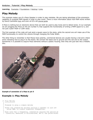
![* modulation (PWM) to create that vibration.
* We calculate the pulse-width to be half the period; we pulse
* the speaker HIGH for 'pulse-width' microseconds, then LOW
* for 'pulse-width' microseconds.
* This pulsing creates a vibration of the desired frequency.
*
* (cleft) 2005 D. Cuartielles for K3
* Refactoring and comments 2006 clay.shirky@nyu.edu
* See NOTES in comments at end for possible improvements
*/
// TONES ==========================================
// Start by defining the relationship between
// note, period, frequency.
#define c 3830 // 261 Hz
#define d 3400 // 294 Hz
#define e 3038 // 329 Hz
#define f 2864 // 349 Hz
#define g 2550 // 392 Hz
#define a 2272 // 440 Hz
#define b 2028 // 493 Hz
#define C 1912 // 523 Hz
// Define a special note, 'R', to represent a rest
#define R 0
// SETUP ============================================
// Set up speaker on a PWM pin (digital 9, 10 or 11)
int speakerOut = 9;
// Do we want debugging on serial out? 1 for yes, 0 for no
int DEBUG = 1;
void setup() {
pinMode(speakerOut, OUTPUT);
if (DEBUG) {
Serial.begin(9600); // Set serial out if we want debugging
}
}
// MELODY and TIMING =======================================
// melody[] is an array of notes, accompanied by beats[],
// which sets each note's relative length (higher #, longer note)
int melody[] = { C, b, g, C, b, e, R, C, c, g, a, C };
int beats[] = { 16, 16, 16, 8, 8, 16, 32, 16, 16, 16, 8, 8 };
int MAX_COUNT = sizeof(melody) / 2; // Melody length, for looping.
// Set overall tempo
long tempo = 10000;
// Set length of pause between notes
int pause = 1000;
// Loop variable to increase Rest length
int rest_count = 100; //-BLETCHEROUS HACK; See NOTES
// Initialize core variables
int tone = 0;
int beat = 0;
long duration = 0;
// PLAY TONE ==============================================
// Pulse the speaker to play a tone for a particular duration
void playTone() {
long elapsed_time = 0;
if (tone 0) { // if this isn't a Rest beat, while the tone has
// played less long than 'duration', pulse speaker HIGH and LOW
while (elapsed_time duration) {
digitalWrite(speakerOut,HIGH);
delayMicroseconds(tone / 2);
// DOWN
digitalWrite(speakerOut, LOW);
delayMicroseconds(tone / 2);
// Keep track of how long we pulsed
elapsed_time += (tone);
}
}
else { // Rest beat; loop times delay
for (int j = 0; j rest_count; j++) { // See NOTE on rest_count
delayMicroseconds(duration);
}](https://image.slidesharecdn.com/arduino-learning-111105084504-phpapp01/85/Arduino-learning-361-320.jpg)
![}
}
// LET THE WILD RUMPUS BEGIN =============================
void loop() {
// Set up a counter to pull from melody[] and beats[]
for (int i=0; iMAX_COUNT; i++) {
tone = melody[i];
beat = beats[i];
duration = beat * tempo; // Set up timing
playTone();
// A pause between notes...
delayMicroseconds(pause);
if (DEBUG) { // If debugging, report loop, tone, beat, and duration
Serial.print(i);
Serial.print(:);
Serial.print(beat);
Serial.print( );
Serial.print(tone);
Serial.print( );
Serial.println(duration);
}
}
}
/*
* NOTES
* The program purports to hold a tone for 'duration' microseconds.
* Lies lies lies! It holds for at least 'duration' microseconds, _plus_
* any overhead created by incremeting elapsed_time (could be in excess of
* 3K microseconds) _plus_ overhead of looping and two digitalWrites()
*
* As a result, a tone of 'duration' plays much more slowly than a rest
* of 'duration.' rest_count creates a loop variable to bring 'rest' beats
* in line with 'tone' beats of the same length.
*
* rest_count will be affected by chip architecture and speed, as well as
* overhead from any program mods. Past behavior is no guarantee of future
* performance. Your mileage may vary. Light fuse and get away.
*
* This could use a number of enhancements:
* ADD code to let the programmer specify how many times the melody should
* loop before stopping
* ADD another octave
* MOVE tempo, pause, and rest_count to #define statements
* RE-WRITE to include volume, using analogWrite, as with the second program at
* http://www.arduino.cc/en/Tutorial/PlayMelody
* ADD code to make the tempo settable by pot or other input device
* ADD code to take tempo or volume settable by serial communication
* (Requires 0005 or higher.)
* ADD code to create a tone offset (higer or lower) through pot etc
* REPLACE random melody with opening bars to 'Smoke on the Water'
*/
Second version, with volume control set using analogWrite()
/* Play Melody
* -----------
*
* Program to play melodies stored in an array, it requires to know
* about timing issues and about how to play tones.
*
* The calculation of the tones is made following the mathematical
* operation:
*
* timeHigh = 1/(2 * toneFrequency) = period / 2
*
* where the different tones are described as in the table:
*
* note frequency period PW (timeHigh)
* c 261 Hz 3830 1915
* d 294 Hz 3400 1700
* e 329 Hz 3038 1519
* f 349 Hz 2864 1432](https://image.slidesharecdn.com/arduino-learning-111105084504-phpapp01/85/Arduino-learning-362-320.jpg)
![* g 392 Hz 2550 1275
* a 440 Hz 2272 1136
* b 493 Hz 2028 1014
* C 523 Hz 1912 956
*
* (cleft) 2005 D. Cuartielles for K3
*/
int ledPin = 13;
int speakerOut = 9;
byte names[] = {'c', 'd', 'e', 'f', 'g', 'a', 'b', 'C'};
int tones[] = {1915, 1700, 1519, 1432, 1275, 1136, 1014, 956};
byte melody[] = 2d2a1f2c2d2a2d2c2f2d2a2c2d2a1f2c2d2a2a2g2p8p8p8p;
// count length: 1 2 3 4 5 6 7 8 9 0 1 2 3 4 5 6 7 8 9 0 1 2 3 4 5 6 7 8 9 0
// 10 20 30
int count = 0;
int count2 = 0;
int count3 = 0;
int MAX_COUNT = 24;
int statePin = LOW;
void setup() {
pinMode(ledPin, OUTPUT);
}
void loop() {
analogWrite(speakerOut, 0);
for (count = 0; count MAX_COUNT; count++) {
statePin = !statePin;
digitalWrite(ledPin, statePin);
for (count3 = 0; count3 = (melody[count*2] - 48) * 30; count3++) {
for (count2=0;count28;count2++) {
if (names[count2] == melody[count*2 + 1]) {
analogWrite(speakerOut,500);
delayMicroseconds(tones[count2]);
analogWrite(speakerOut, 0);
delayMicroseconds(tones[count2]);
}
if (melody[count*2 + 1] == 'p') {
// make a pause of a certain size
analogWrite(speakerOut, 0);
delayMicroseconds(500);
}
}
}
}
}
(Printable View of http://www.arduino.cc/en/Tutorial/PlayMelody)](https://image.slidesharecdn.com/arduino-learning-111105084504-phpapp01/85/Arduino-learning-363-320.jpg)

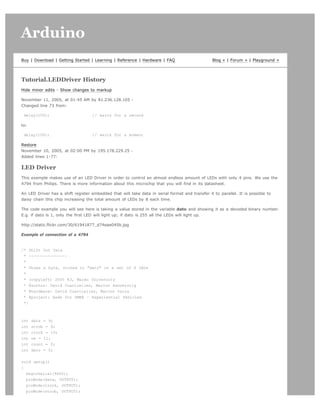
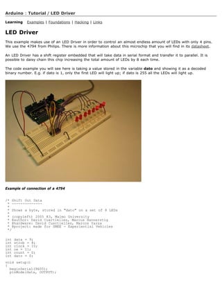
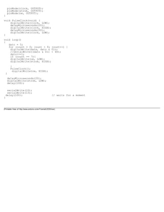

![Arduino search
Buy | Download | Getting Started | Learning | Reference | Hardware | FAQ Blog » | Forum » | Playground »
Tutorial.LCD8Bits History
Hide minor edits - Show changes to markup
October 17, 2005, at 07:00 PM by 195.178.229.25 -
Changed lines 1-121 from:
http://static.flickr.com/25/53544993_3611fce234_o.jpg
to:
LCD Display - 8 bits
This example shows the most basic action to be done with a LCD display: to show a welcome message. In our case we have
an LCD display with backlight and contrast control. Therefore we will use a potentiometer to regulate the contrast.
LCD displays are most of the times driven using an industrial standard established by Hitachi. According to it there is a group
of pins dedicated to sending data and locations of that data on the screen, the user can choose to use 4 or 8 pins to send
data. On top of that three more pins are needed to synchronize the communication towards the display.
The backdrop of this example is that we are using almost all the available pins on Arduino board in order to drive the display,
but we have decided to show it this way for simplicity.
http://static.flickr.com/25/53544993_3611fce234.jpg
Picture of a protoboard supporting the display and a potentiometer
/* LCD Hola
* --------
*
* This is the first example in how to use an LCD screen
* configured with data transfers over 8 bits. The example
* uses all the digital pins on the Arduino board, but can
* easily display data on the display
*
* There are the following pins to be considered:
*
* - DI, RW, DB0..DB7, Enable (11 in total)
*
* the pinout for LCD displays is standard and there is plenty
* of documentation to be found on the internet.
*
* (cleft) 2005 DojoDave for K3
*
*/
int DI = 12;
int RW = 11;
int DB[] = {3, 4, 5, 6, 7, 8, 9, 10};
int Enable = 2;
void LcdCommandWrite(int value) {
// poll all the pins
int i = 0;
for (i=DB[0]; i = DI; i++) {
digitalWrite(i,value 01);](https://image.slidesharecdn.com/arduino-learning-111105084504-phpapp01/85/Arduino-learning-370-320.jpg)
![value = 1;
}
digitalWrite(Enable,LOW);
delayMicroseconds(1);
// send a pulse to enable
digitalWrite(Enable,HIGH);
delayMicroseconds(1); // pause 1 ms according to datasheet
digitalWrite(Enable,LOW);
delayMicroseconds(1); // pause 1 ms according to datasheet
}
void LcdDataWrite(int value) {
// poll all the pins
int i = 0;
digitalWrite(DI, HIGH);
digitalWrite(RW, LOW);
for (i=DB[0]; i = DB[7]; i++) {
digitalWrite(i,value 01);
value = 1;
}
digitalWrite(Enable,LOW);
delayMicroseconds(1);
// send a pulse to enable
digitalWrite(Enable,HIGH);
delayMicroseconds(1);
digitalWrite(Enable,LOW);
delayMicroseconds(1); // pause 1 ms according to datasheet
}
void setup (void) {
int i = 0;
for (i=Enable; i = DI; i++) {
pinMode(i,OUTPUT);
}
delay(100);
// initiatize lcd after a short pause
// needed by the LCDs controller
LcdCommandWrite(0x30); // function set:
// 8-bit interface, 1 display lines, 5x7 font
delay(64);
LcdCommandWrite(0x30); // function set:
// 8-bit interface, 1 display lines, 5x7 font
delay(50);
LcdCommandWrite(0x30); // function set:
// 8-bit interface, 1 display lines, 5x7 font
delay(20);
LcdCommandWrite(0x06); // entry mode set:
// increment automatically, no display shift
delay(20);
LcdCommandWrite(0x0E); // display control:
// turn display on, cursor on, no blinking
delay(20);
LcdCommandWrite(0x01); // clear display, set cursor position to zero
delay(100);
LcdCommandWrite(0x80); // display control:
// turn display on, cursor on, no blinking
delay(20);
}
void loop (void) {
LcdCommandWrite(0x02); // set cursor position to zero
delay(10);
// Write the welcome message
LcdDataWrite('H');
LcdDataWrite('o');](https://image.slidesharecdn.com/arduino-learning-111105084504-phpapp01/85/Arduino-learning-371-320.jpg)
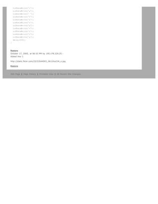
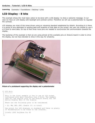
![int DI = 12;
int RW = 11;
int DB[] = {3, 4, 5, 6, 7, 8, 9, 10};
int Enable = 2;
void LcdCommandWrite(int value) {
// poll all the pins
int i = 0;
for (i=DB[0]; i = DI; i++) {
digitalWrite(i,value 01);
value = 1;
}
digitalWrite(Enable,LOW);
delayMicroseconds(1);
// send a pulse to enable
digitalWrite(Enable,HIGH);
delayMicroseconds(1); // pause 1 ms according to datasheet
digitalWrite(Enable,LOW);
delayMicroseconds(1); // pause 1 ms according to datasheet
}
void LcdDataWrite(int value) {
// poll all the pins
int i = 0;
digitalWrite(DI, HIGH);
digitalWrite(RW, LOW);
for (i=DB[0]; i = DB[7]; i++) {
digitalWrite(i,value 01);
value = 1;
}
digitalWrite(Enable,LOW);
delayMicroseconds(1);
// send a pulse to enable
digitalWrite(Enable,HIGH);
delayMicroseconds(1);
digitalWrite(Enable,LOW);
delayMicroseconds(1); // pause 1 ms according to datasheet
}
void setup (void) {
int i = 0;
for (i=Enable; i = DI; i++) {
pinMode(i,OUTPUT);
}
delay(100);
// initiatize lcd after a short pause
// needed by the LCDs controller
LcdCommandWrite(0x30); // function set:
// 8-bit interface, 1 display lines, 5x7 font
delay(64);
LcdCommandWrite(0x30); // function set:
// 8-bit interface, 1 display lines, 5x7 font
delay(50);
LcdCommandWrite(0x30); // function set:
// 8-bit interface, 1 display lines, 5x7 font
delay(20);
LcdCommandWrite(0x06); // entry mode set:
// increment automatically, no display shift
delay(20);
LcdCommandWrite(0x0E); // display control:
// turn display on, cursor on, no blinking
delay(20);
LcdCommandWrite(0x01); // clear display, set cursor position to zero
delay(100);
LcdCommandWrite(0x80); // display control:
// turn display on, cursor on, no blinking
delay(20);
}
void loop (void) {
LcdCommandWrite(0x02); // set cursor position to zero
delay(10);
// Write the welcome message
LcdDataWrite('H');
LcdDataWrite('o');
LcdDataWrite('l');
LcdDataWrite('a');
LcdDataWrite(' ');
LcdDataWrite('C');
LcdDataWrite('a');
LcdDataWrite('r');](https://image.slidesharecdn.com/arduino-learning-111105084504-phpapp01/85/Arduino-learning-374-320.jpg)


![Restore
August 02, 2006, at 12:22 PM by Heather Dewey-Hagborg -
Changed lines 18-19 from:
Unzip the files and place the whole LiquidCrystal folder inside your arduino-0004libtargetslibraries folder. Start the Arduino
program and check to make sure LiquidCrystal is now available as an option in the Sketch menu under import library.
to:
Unzip the files and place the whole LiquidCrystal folder inside your arduino-0004libtargetslibraries folder. Start the Arduino
program and check to make sure LiquidCrystal is now available as an option in the Sketch menu under Import Library.
Restore
August 02, 2006, at 12:20 PM by Heather Dewey-Hagborg -
Changed lines 17-18 from:
Attach:LiquidCrystal.zip Download the LiquidCrystal library .
to:
Download the LiquidCrystal library here.
Restore
August 02, 2006, at 12:16 PM by Heather Dewey-Hagborg -
Added line 17:
Attach:LiquidCrystal.zip
Restore
August 02, 2006, at 12:14 PM by Heather Dewey-Hagborg -
Added lines 14-19:
Install the Library
For a basic explanation of how libraries work in Arduino read the library page. Download the LiquidCrystal library . Unzip the
files and place the whole LiquidCrystal folder inside your arduino-0004libtargetslibraries folder. Start the Arduino program
and check to make sure LiquidCrystal is now available as an option in the Sketch menu under import library.
Restore
August 02, 2006, at 12:08 PM by Heather Dewey-Hagborg -
Changed line 146 from:
To interface an LCD directly in Arduino code see .
to:
To interface an LCD directly in Arduino code see this example.
Restore
August 02, 2006, at 12:08 PM by Heather Dewey-Hagborg -
Added lines 145-146:
To interface an LCD directly in Arduino code see .
Restore
August 02, 2006, at 12:04 PM by Heather Dewey-Hagborg -
Changed lines 127-131 from:
1. include LiquidCrystal.h
LiquidCrystal lcd = LiquidCrystal(); char string1[] = Hello!;
to:
1. include LiquidCrystal.h //include LiquidCrystal library
LiquidCrystal lcd = LiquidCrystal(); //create a LiquidCrystal object to control an LCD char string1[] = Hello!; //variable to
store the string Hello!
Changed lines 133-134 from:
lcd.init();
digitalWrite(13,HIGH);](https://image.slidesharecdn.com/arduino-learning-111105084504-phpapp01/85/Arduino-learning-380-320.jpg)
![to:
lcd.init(); //initialize the LCD
digitalWrite(13,HIGH); //turn on an LED for debugging
Changed lines 137-141 from:
lcd.commandWrite(2);
delay(1000);
lcd.printIn(string1);
delay(1000);
}
to:
lcd.commandWrite(2); //bring the cursor to the starting position
delay(1000); //delay 1000 ms to view change
lcd.printIn(string1); //send the string to the LCD
delay(1000); //delay 1000 ms to view change
} //repeat forever
Changed lines 144-145 from:
Using this code makes the cursor jump back and forth between the end of the message an the home position.
to:
This code makes the cursor jump back and forth between the end of the message an the home position.
Restore
August 02, 2006, at 12:02 PM by Heather Dewey-Hagborg -
Changed lines 107-111 from:
1. include LiquidCrystal.h
LiquidCrystal lcd = LiquidCrystal(); char string1[] = Hello!;
to:
1. include LiquidCrystal.h //include LiquidCrystal library
LiquidCrystal lcd = LiquidCrystal(); //create a LiquidCrystal object to control an LCD char string1[] = Hello!; //variable to
store the string Hello!
Changed lines 113-114 from:
lcd.init();
digitalWrite(13,HIGH);
to:
lcd.init(); //initialize the LCD
digitalWrite(13,HIGH); //turn on an LED for debugging
Changed lines 117-121 from:
lcd.clear();
delay(1000);
lcd.printIn(string1);
delay(1000);
}
to:
lcd.clear(); //clear the display
delay(1000); //delay 1000 ms to view change
lcd.printIn(string1); //send the string to the LCD
delay(1000); //delay 1000 ms to view change
} //repeat forever](https://image.slidesharecdn.com/arduino-learning-111105084504-phpapp01/85/Arduino-learning-381-320.jpg)
![}
Finally, you should know there is a lot of functionality in the HD44780 chip interface that is not drawn out into Arduino
functions. If you are feeling ambitious glance over the datasheet and try out some of the direct commands using the
commandWrite() function. For example, commandWrite(2) tells the board to move the cursor back to starting position.
to:
@]
Finally, you should know there is a lot of functionality in the HD44780 chip interface that is not drawn out into Arduino
functions. If you are feeling ambitious glance over the datasheet and try out some of the direct commands using the
commandWrite() function. For example, commandWrite(2) tells the board to move the cursor back to starting position. Here
is an example:
Added line 122:
Added line 125:
Changed line 138 from:
Using this code makes the cursorjump back and forth between the end of the message an the home position.
to:
Using this code makes the cursor jump back and forth between the end of the message an the home position.
Restore
August 02, 2006, at 11:17 AM by Heather Dewey-Hagborg -
Changed lines 54-55 from:
1. include
to:
1. include LiquidCrystal.h
Added line 57:
Changed lines 70-72 from:
Now letÕs try something a little more interesting. Compile and upload the following code to the Arduino.
1. include
to:
Now let's try something a little more interesting. Compile and upload the following code to the Arduino.
[@
1. include LiquidCrystal.h
Added line 78:](https://image.slidesharecdn.com/arduino-learning-111105084504-phpapp01/85/Arduino-learning-385-320.jpg)
![Changed lines 91-92 from:
}
to:
@]
Changed line 97 from:
1. include
to:
1. include LiquidCrystal.h
Changed line 114 from:
1. include
to:
1. include LiquidCrystal.h
Restore
August 02, 2006, at 11:14 AM by Heather Dewey-Hagborg -
Changed lines 3-4 from:
In this tutorial you will control a Liquid Crystal Display (LCD) using the Arduino LiquidCrystal library. The library provides
functions for accessing any LCD using the common HD44780 parallel interface chipset, such as those available from Sparkfun.
It currently implements 8-bit control and one line display of 5x7 characters. Functions are provided to initialize the screen, to
print characters and strings, to clear the screen, and to send commands directly to the HD44780 chip. This tutorial will walk
you through the steps of wiring an LCD to an Arduino microcontroller board and implementing each of these functions.
to:
In this tutorial you will control a Liquid Crystal Display (LCD) using the Arduino LiquidCrystal library. The library provides
functions for accessing any LCD using the common HD44780 parallel interface chipset, such as those available from Sparkfun.
It currently implements 8-bit control and one line display of 5x7 characters. Functions are provided to initialize the screen, to
print characters and strings, to clear the screen, and to send commands directly to the HD44780 chip. This tutorial will walk
you through the steps of wiring an LCD to an Arduino microcontroller board and implementing each of these functions.
Added line 25:
[@
Changed lines 38-39 from:
to:
@]
Changed line 53 from:
to:
[@
Changed lines 57-58 from:
lcd.init(); digitalWrite(13,HIGH);
to:
lcd.init();
digitalWrite(13,HIGH);
Added line 60:
Changed line 62 from:
delay(1000);
to:
delay(1000);
Changed lines 64-65 from:](https://image.slidesharecdn.com/arduino-learning-111105084504-phpapp01/85/Arduino-learning-386-320.jpg)
![}
to:
@]
Restore
August 02, 2006, at 11:12 AM by Heather Dewey-Hagborg -
Changed lines 1-2 from:
Arduino Liquid Crystal Display Interface
to:
Arduino Liquid Crystal Library LCD Interface
Changed lines 7-15 from:
* Solderless breadboard
* Hookup wire
* Arduino Microcontoller Module
* Potentiometer
* Liquid Crystal Display (LCD) with HD44780 chip interface
* Light emitting Diode (LED) - optional, for debugging
Prepare the breadboard
to:
Solderless breadboard
Hookup wire
Arduino Microcontoller Module
Potentiometer
Liquid Crystal Display (LCD) with HD44780 chip interface
Light emitting Diode (LED) - optional, for debugging
Prepare the breadboard
Added lines 22-23:
Added lines 38-39:](https://image.slidesharecdn.com/arduino-learning-111105084504-phpapp01/85/Arduino-learning-387-320.jpg)
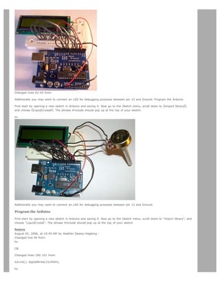
![lcd.init();
digitalWrite(13,HIGH);
Changed lines 104-107 from:
lcd.commandWrite(2); delay(1000); lcd.printIn(string1); delay(1000);
to:
lcd.commandWrite(2);
delay(1000);
lcd.printIn(string1);
delay(1000);
Changed lines 109-110 from:
}
to:
@]
Restore
August 02, 2006, at 10:42 AM by Heather Dewey-Hagborg -
Added lines 1-111:
Arduino Liquid Crystal Display Interface
In this tutorial you will control a Liquid Crystal Display (LCD) using the Arduino LiquidCrystal library. The library provides
functions for accessing any LCD using the common HD44780 parallel interface chipset, such as those available from Sparkfun.
It currently implements 8-bit control and one line display of 5x7 characters. Functions are provided to initialize the screen, to
print characters and strings, to clear the screen, and to send commands directly to the HD44780 chip. This tutorial will walk
you through the steps of wiring an LCD to an Arduino microcontroller board and implementing each of these functions.
Materials needed:
* Solderless breadboard
* Hookup wire
* Arduino Microcontoller Module
* Potentiometer
* Liquid Crystal Display (LCD) with HD44780 chip interface
* Light emitting Diode (LED) - optional, for debugging
Prepare the breadboard
Solder a header to the LCD board if one is not present already.
Insert the LCD header into the breadboard and connect power and ground on the breadboard to power and ground from the
microcontroller. On the Arduino module, use the 5V and any of the ground connections:
Connect wires from the breadboard to the arduino input sockets. Look at the datasheet for your LCD board to figure out
which pins are where. The pinout is as follows: Arduino LCD 2 Enable 3 Data Bit 0 (DB0) 4 (DB1) 5 (DB2) 6 (DB3) 7 (DB4)
8 (DB5) 9 (DB6) 10 (DB7) 11 Read/Write (RW) 12 Register Select (RS)
Connect a potentiometer a a voltage divider between 5V, Ground, and the contrast adjustment pin on your LCD.
Additionally you may want to connect an LED for debugging purposes between pin 13 and Ground. Program the Arduino](https://image.slidesharecdn.com/arduino-learning-111105084504-phpapp01/85/Arduino-learning-389-320.jpg)
![First start by opening a new sketch in Arduino and saving it. Now go to the Sketch menu, scroll down to Òimport libraryÓ,
and choose ÒLiquidCrystalÓ. The phrase #include should pop up at the top of your sketch.
The first program we are going to try is simply for calibration and debugging. Copy the following code into your sketch,
compile and upload to the Arduino.
1. include
LiquidCrystal lcd = LiquidCrystal(); void setup(void){ lcd.init(); digitalWrite(13,HIGH); } void loop(void){ delay(1000); } }
If all went as planned both the LCD and the LED should turn on. Now you can use the potentiometer to adjust the contrast
on the LCD until you can clearly see a cursor at the beginning of the first line.
Now letÕs try something a little more interesting. Compile and upload the following code to the Arduino.
1. include
LiquidCrystal lcd = LiquidCrystal(); void setup(void){ lcd.init(); digitalWrite(13,HIGH); } void loop(void){ lcd.clear();
delay(1000); lcd.print('a'); lcd.print('b'); lcd.print('c'); delay(1000); } }
This time you should see the letters a b and c appear and clear from the display in an endless loop.
This is all great fun, but who really wants to type out each letter of a message indivually? Enter the printIn() function. Simply
initialize a string, pass it to printIn(), and now we have ourselves a proper hello world program.
1. include
LiquidCrystal lcd = LiquidCrystal(); char string1[] = Hello!; void setup(void){ lcd.init(); digitalWrite(13,HIGH); } void
loop(void){ lcd.clear(); delay(1000); lcd.printIn(string1); delay(1000); } }
Finally, you should know there is a lot of functionality in the HD44780 chip interface that is not drawn out into Arduino
functions. If you are feeling ambitious glance over the datasheet and try out some of the direct commands using the
commandWrite() function. For example, commandWrite(2) tells the board to move the cursor back to starting position.
1. include
LiquidCrystal lcd = LiquidCrystal(); char string1[] = Hello!; void setup(void){ lcd.init(); digitalWrite(13,HIGH); } void
loop(void){ lcd.commandWrite(2); delay(1000); lcd.printIn(string1); delay(1000); } }
Using this code makes the cursorjump back and forth between the end of the message an the home position.
Restore
Edit Page | Page History | Printable View | All Recent Site Changes](https://image.slidesharecdn.com/arduino-learning-111105084504-phpapp01/85/Arduino-learning-390-320.jpg)
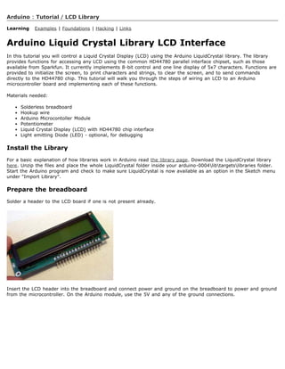
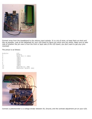
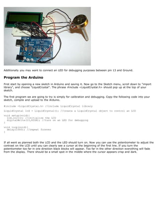
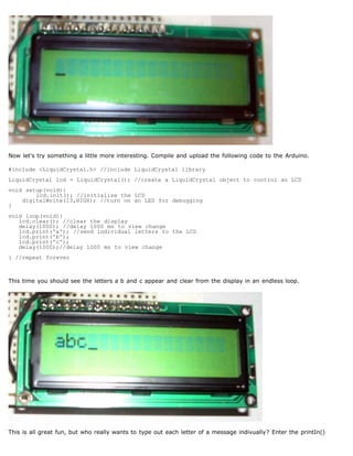
![function. Simply initialize a string, pass it to printIn(), and now we have ourselves a proper hello world program.
#include LiquidCrystal.h //include LiquidCrystal library
LiquidCrystal lcd = LiquidCrystal(); //create a LiquidCrystal object to control an LCD
char string1[] = Hello!; //variable to store the string Hello!
void setup(void){
lcd.init(); //initialize the LCD
digitalWrite(13,HIGH); //turn on an LED for debugging
}
void loop(void){
lcd.clear(); //clear the display
delay(1000); //delay 1000 ms to view change
lcd.printIn(string1); //send the string to the LCD
delay(1000); //delay 1000 ms to view change
} //repeat forever
Finally, you should know there is a lot of functionality in the HD44780 chip interface that is not drawn out into
Arduino functions. If you are feeling ambitious glance over the datasheet and try out some of the direct commands
using the commandWrite() function. For example, commandWrite(2) tells the board to move the cursor back to
starting position. Here is an example:
#include LiquidCrystal.h //include LiquidCrystal library
LiquidCrystal lcd = LiquidCrystal(); //create a LiquidCrystal object to control an LCD
char string1[] = Hello!; //variable to store the string Hello!
void setup(void){
lcd.init(); //initialize the LCD
digitalWrite(13,HIGH); //turn on an LED for debugging
}
void loop(void){
lcd.commandWrite(2); //bring the cursor to the starting position
delay(1000); //delay 1000 ms to view change
lcd.printIn(string1); //send the string to the LCD
delay(1000); //delay 1000 ms to view change
} //repeat forever
This code makes the cursor jump back and forth between the end of the message an the home position.
To interface an LCD directly in Arduino code see this example.
LCD interface library and tutorial by Heather Dewey-Hagborg
(Printable View of http://www.arduino.cc/en/Tutorial/LCDLibrary)](https://image.slidesharecdn.com/arduino-learning-111105084504-phpapp01/85/Arduino-learning-395-320.jpg)

![Unipolar Stepper Motor
This page shows two examples on how to drive a bipolar stepper motor. These motors can be found in old floppy drives and
are easy to control. The one we use has 6 connectors of which one is power (VCC) and the other four are used to drive the
motor sending synchronous signals.
The first example is the basic code to make the motor spin in one direction. It is aiming those that have no knowledge in
how to control stepper motors. The second example is coded in a more complex way, but allows to make the motor spin at
different speeds, in both directions, and controlling both from a potentiometer.
The prototyping board has been populated with a 10K potentiomenter that we connect to an analog input, and a ULN2003A
driver. This chip has a bunch of transistors embedded in a single housing. It allows the connection of devices and
components that need much higher current than the ones that the ATMEGA8 from our Arduino board can offer.
http://static.flickr.com/32/54357295_756c131217.jpg
Picture of a protoboard supporting the ULN2003A and a potentiometer
Example 1: Simple example
/* Stepper Copal
* -------------
*
* Program to drive a stepper motor coming from a 5'25 disk drive
* according to the documentation I found, this stepper: [...] motor
* made by Copal Electronics, with 1.8 degrees per step and 96 ohms
* per winding, with center taps brought out to separate leads [...]
* [http://www.cs.uiowa.edu/~jones/step/example.html]
*
* It is a bipolar stepper motor with 5 wires:
*
* - red: power connector, I have it at 5V and works fine
* - orange and black: coil 1
* - brown and yellow: coil 2
*
* (cleft) 2005 DojoDave for K3
* http://www.0j0.org | http://arduino.berlios.de
*
* @author: David Cuartielles
* @date: 20 Oct. 2005
*/
int motorPin1 = 8;
int motorPin2 = 9;
int motorPin3 = 10;
int motorPin4 = 11;
int delayTime = 500;
void setup() {
pinMode(motorPin1, OUTPUT);
pinMode(motorPin2, OUTPUT);
pinMode(motorPin3, OUTPUT);
pinMode(motorPin4, OUTPUT);
}
void loop() {
digitalWrite(motorPin1, HIGH);
digitalWrite(motorPin2, LOW);
digitalWrite(motorPin3, LOW);
digitalWrite(motorPin4, LOW);
delay(delayTime);
digitalWrite(motorPin1, LOW);
digitalWrite(motorPin2, HIGH);
digitalWrite(motorPin3, LOW);
digitalWrite(motorPin4, LOW);](https://image.slidesharecdn.com/arduino-learning-111105084504-phpapp01/85/Arduino-learning-398-320.jpg)
![delay(delayTime);
digitalWrite(motorPin1, LOW);
digitalWrite(motorPin2, LOW);
digitalWrite(motorPin3, HIGH);
digitalWrite(motorPin4, LOW);
delay(delayTime);
digitalWrite(motorPin1, LOW);
digitalWrite(motorPin2, LOW);
digitalWrite(motorPin3, LOW);
digitalWrite(motorPin4, HIGH);
delay(delayTime);
}
Example 2: Stepper Bipolar Advanced
/* Stepper Bipolar Advanced
* ------------------------
*
* Program to drive a stepper motor coming from a 5'25 disk drive
* according to the documentation I found, this stepper: [...] motor
* made by Copal Electronics, with 1.8 degrees per step and 96 ohms
* per winding, with center taps brought out to separate leads [...]
* [http://www.cs.uiowa.edu/~jones/step/example.html]
*
* It is a bipolar stepper motor with 5 wires:
*
* - red: power connector, I have it at 5V and works fine
* - orange and black: coil 1
* - brown and yellow: coil 2
*
* (cleft) 2005 DojoDave for K3
* http://www.0j0.org | http://arduino.berlios.de
*
* @author: David Cuartielles
* @date: 20 Oct. 2005
*/
int motorPins[] = {8, 9, 10, 11};
int count = 0;
int count2 = 0;
int delayTime = 500;
int val = 0;
void setup() {
pinMode(ledPin, OUTPUT);
for (count = 0; count 4; count++) {
pinMode(motorPins[count], OUTPUT);
}
}
void moveForward() {
if ((count2 == 0) || (count2 == 1)) {
count2 = 16;
}
count2=1;
for (count = 3; count = 0; count--) {
digitalWrite(motorPins[count], count2count0x01);
}
delay(delayTime);
}
void moveBackward() {](https://image.slidesharecdn.com/arduino-learning-111105084504-phpapp01/85/Arduino-learning-399-320.jpg)
![if ((count2 == 0) || (count2 == 1)) {
count2 = 16;
}
count2=1;
for (count = 3; count = 0; count--) {
digitalWrite(motorPins[3 - count], count2count0x01);
}
delay(delayTime);
}
void loop() {
val = analogRead(0);
if (val 540) {
// move faster the higher the value from the potentiometer
delayTime = 2048 - 1024 * val / 512 + 1;
moveForward();
} else if (val 480) {
// move faster the lower the value from the potentiometer
delayTime = 1024 * val / 512 + 1;
moveBackward();
} else {
delayTime = 1024;
}
}
References
In order to work out this example, we have been looking into quite a lot of documentation. The following links may be useful
for you to visit in order to understand the theory underlying behind stepper motors:
- information about the motor we are using - here
- basic explanation about steppers - here
- good PDF with basic information - here
Restore
Edit Page | Page History | Printable View | All Recent Site Changes](https://image.slidesharecdn.com/arduino-learning-111105084504-phpapp01/85/Arduino-learning-400-320.jpg)
![Arduino : Tutorial / Stepper Unipolar
Learning Examples | Foundations | Hacking | Links
Unipolar Stepper Motor
This page shows two examples on how to drive a unipolar stepper motor. These motors can be found in old floppy
drives and are easy to control. The one we use has 6 connectors of which one is power (VCC) and the other four
are used to drive the motor sending synchronous signals.
The first example is the basic code to make the motor spin in one direction. It is aiming those that have no
knowledge in how to control stepper motors. The second example is coded in a more complex way, but allows to
make the motor spin at different speeds, in both directions, and controlling both from a potentiometer.
The prototyping board has been populated with a 10K potentiomenter that we connect to an analog input, and a
ULN2003A driver. This chip has a bunch of transistors embedded in a single housing. It allows the connection of
devices and components that need much higher current than the ones that the ATMEGA8 from our Arduino board
can offer.
Picture of a protoboard supporting the ULN2003A and a potentiometer
Example 1: Simple example
/* Stepper Copal
* -------------
*
* Program to drive a stepper motor coming from a 5'25 disk drive
* according to the documentation I found, this stepper: [...] motor
* made by Copal Electronics, with 1.8 degrees per step and 96 ohms
* per winding, with center taps brought out to separate leads [...]
* [http://www.cs.uiowa.edu/~jones/step/example.html]
*
* It is a unipolar stepper motor with 5 wires:
*
* - red: power connector, I have it at 5V and works fine
* - orange and black: coil 1
* - brown and yellow: coil 2](https://image.slidesharecdn.com/arduino-learning-111105084504-phpapp01/85/Arduino-learning-401-320.jpg)
![*
* (cleft) 2005 DojoDave for K3
* http://www.0j0.org | http://arduino.berlios.de
*
* @author: David Cuartielles
* @date: 20 Oct. 2005
*/
int motorPin1 = 8;
int motorPin2 = 9;
int motorPin3 = 10;
int motorPin4 = 11;
int delayTime = 500;
void setup() {
pinMode(motorPin1, OUTPUT);
pinMode(motorPin2, OUTPUT);
pinMode(motorPin3, OUTPUT);
pinMode(motorPin4, OUTPUT);
}
void loop() {
digitalWrite(motorPin1, HIGH);
digitalWrite(motorPin2, LOW);
digitalWrite(motorPin3, LOW);
digitalWrite(motorPin4, LOW);
delay(delayTime);
digitalWrite(motorPin1, LOW);
digitalWrite(motorPin2, HIGH);
digitalWrite(motorPin3, LOW);
digitalWrite(motorPin4, LOW);
delay(delayTime);
digitalWrite(motorPin1, LOW);
digitalWrite(motorPin2, LOW);
digitalWrite(motorPin3, HIGH);
digitalWrite(motorPin4, LOW);
delay(delayTime);
digitalWrite(motorPin1, LOW);
digitalWrite(motorPin2, LOW);
digitalWrite(motorPin3, LOW);
digitalWrite(motorPin4, HIGH);
delay(delayTime);
}
Example 2: Stepper Unipolar Advanced
/* Stepper Unipolar Advanced
* -------------------------
*
* Program to drive a stepper motor coming from a 5'25 disk drive
* according to the documentation I found, this stepper: [...] motor
* made by Copal Electronics, with 1.8 degrees per step and 96 ohms
* per winding, with center taps brought out to separate leads [...]
* [http://www.cs.uiowa.edu/~jones/step/example.html]
*
* It is a unipolar stepper motor with 5 wires:
*
* - red: power connector, I have it at 5V and works fine
* - orange and black: coil 1
* - brown and yellow: coil 2
*
* (cleft) 2005 DojoDave for K3
* http://www.0j0.org | http://arduino.berlios.de
*
* @author: David Cuartielles
* @date: 20 Oct. 2005
*/
int motorPins[] = {8, 9, 10, 11};
int count = 0;
int count2 = 0;
int delayTime = 500;
int val = 0;
void setup() {
for (count = 0; count 4; count++) {](https://image.slidesharecdn.com/arduino-learning-111105084504-phpapp01/85/Arduino-learning-402-320.jpg)
![pinMode(motorPins[count], OUTPUT);
}
}
void moveForward() {
if ((count2 == 0) || (count2 == 1)) {
count2 = 16;
}
count2=1;
for (count = 3; count = 0; count--) {
digitalWrite(motorPins[count], count2count0x01);
}
delay(delayTime);
}
void moveBackward() {
if ((count2 == 0) || (count2 == 1)) {
count2 = 16;
}
count2=1;
for (count = 3; count = 0; count--) {
digitalWrite(motorPins[3 - count], count2count0x01);
}
delay(delayTime);
}
void loop() {
val = analogRead(0);
if (val 540) {
// move faster the higher the value from the potentiometer
delayTime = 2048 - 1024 * val / 512 + 1;
moveForward();
} else if (val 480) {
// move faster the lower the value from the potentiometer
delayTime = 1024 * val / 512 + 1;
moveBackward();
} else {
delayTime = 1024;
}
}
References
In order to work out this example, we have been looking into quite a lot of documentation. The following links may
be useful for you to visit in order to understand the theory underlying behind stepper motors:
- information about the motor we are using - here
- basic explanation about steppers - here
- good PDF with basic information - here
(Printable View of http://www.arduino.cc/en/Tutorial/StepperUnipolar)](https://image.slidesharecdn.com/arduino-learning-111105084504-phpapp01/85/Arduino-learning-403-320.jpg)

![Arduino search
Buy | Download | Getting Started | Learning | Reference | Hardware | FAQ Blog » | Forum » | Playground »
Tutorial.DMXMaster History
Hide minor edits - Show changes to markup
January 30, 2007, at 03:35 PM by David A. Mellis -
Changed lines 2-176 from:
full tutorial coming soon
/* DMX Shift Out
* -------------
*
* Shifts data in DMX format out to DMX enabled devices
* it is extremely restrictive in terms of timing. Therefore
* the program will stop the interrupts when sending data
*
* (cleft) 2006 by Tomek Ness and D. Cuartielles
* K3 - School of Arts and Communication
* http://www.arduino.cc
* http://www.mah.se/k3
*
* @date: 2006-01-19
* @idea: Tomek Ness
* @code: D. Cuartielles and Tomek Ness
* @acknowledgements: Johny Lowgren for his DMX devices
*
*/
int sig = 3; // signal (plus / dmx pin 3)
int sigI = 2; // signal inversion (minus / dmx pin 2)
int count = 0;
/* Sends a DMX byte out on a pin. Assumes a 16 MHz clock.
* Disables interrupts, which will disrupt the millis() function if used
* too frequently. */
void shiftDmxOut(int pin, int ipin, int theByte)
{
int theDelay = 1;
int count = 0;
int portNumber = port_to_output[digitalPinToPort(pin)];
int pinNumber = digitalPinToBit(pin);
int iPortNumber = port_to_output[digitalPinToPort(ipin)];
int iPinNumber = digitalPinToBit(ipin);
// the first thing we do is to write te pin to high
// it will be the mark between bytes. It may be also
// high from before
_SFR_BYTE(_SFR_IO8(portNumber)) |= _BV(pinNumber);
_SFR_BYTE(_SFR_IO8(iPortNumber)) = ~_BV(iPinNumber);
delayMicroseconds(20);
if (digitalPinToPort(pin) != NOT_A_PIN) {
// If the pin that support PWM output, we need to turn it off](https://image.slidesharecdn.com/arduino-learning-111105084504-phpapp01/85/Arduino-learning-405-320.jpg)
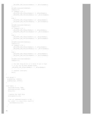
![Please see this updated tutorial on the playground.
Restore
January 19, 2006, at 05:03 PM by 195.178.229.101 -
Added lines 1-176:
DMX Master Device
full tutorial coming soon
/* DMX Shift Out
* -------------
*
* Shifts data in DMX format out to DMX enabled devices
* it is extremely restrictive in terms of timing. Therefore
* the program will stop the interrupts when sending data
*
* (cleft) 2006 by Tomek Ness and D. Cuartielles
* K3 - School of Arts and Communication
* http://www.arduino.cc
* http://www.mah.se/k3
*
* @date: 2006-01-19
* @idea: Tomek Ness
* @code: D. Cuartielles and Tomek Ness
* @acknowledgements: Johny Lowgren for his DMX devices
*
*/
int sig = 3; // signal (plus / dmx pin 3)
int sigI = 2; // signal inversion (minus / dmx pin 2)
int count = 0;
/* Sends a DMX byte out on a pin. Assumes a 16 MHz clock.
* Disables interrupts, which will disrupt the millis() function if used
* too frequently. */
void shiftDmxOut(int pin, int ipin, int theByte)
{
int theDelay = 1;
int count = 0;
int portNumber = port_to_output[digitalPinToPort(pin)];
int pinNumber = digitalPinToBit(pin);
int iPortNumber = port_to_output[digitalPinToPort(ipin)];
int iPinNumber = digitalPinToBit(ipin);
// the first thing we do is to write te pin to high
// it will be the mark between bytes. It may be also
// high from before
_SFR_BYTE(_SFR_IO8(portNumber)) |= _BV(pinNumber);
_SFR_BYTE(_SFR_IO8(iPortNumber)) = ~_BV(iPinNumber);
delayMicroseconds(20);
if (digitalPinToPort(pin) != NOT_A_PIN) {
// If the pin that support PWM output, we need to turn it off
// before doing a digital write.
if (analogOutPinToBit(pin) == 1)
timer1PWMAOff();
if (analogOutPinToBit(pin) == 2)
timer1PWMBOff();
}
// disable interrupts, otherwise the timer 0 overflow interrupt that](https://image.slidesharecdn.com/arduino-learning-111105084504-phpapp01/85/Arduino-learning-408-320.jpg)
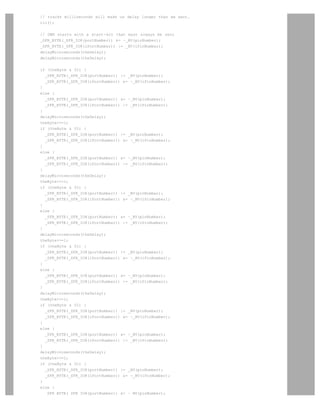
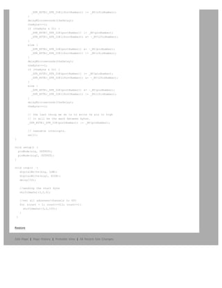

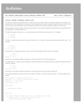

![Arduino search
Buy | Download | Getting Started | Learning | Reference | Hardware | FAQ Blog » | Forum » | Playground »
Tutorial.SoftwareSerial History
Hide minor edits - Show changes to markup
February 26, 2007, at 10:40 AM by David A. Mellis -
Added lines 3-4:
Note: If you just want to use a software serial interface, see the SoftwareSerial library included with Arduino 0007 and later.
Read on if you'd like to know how that library works.
Restore
September 05, 2006, at 12:55 PM by Heather Dewey-Hagborg -
Changed lines 214-216 from:
}@]
to:
}@]
code and tutorial by Heather Dewey-Hagborg
Restore
August 29, 2006, at 12:46 PM by Heather Dewey-Hagborg -
Changed lines 53-54 from:
to:](https://image.slidesharecdn.com/arduino-learning-111105084504-phpapp01/85/Arduino-learning-415-320.jpg)
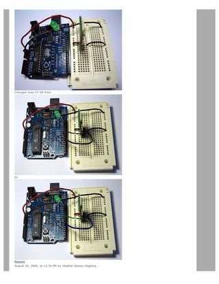
![3. define bit4800Delay 188
4. define halfBit4800Delay 94
Deleted lines 38-55:
Sends a byte long integer value out the software serial connection
Example:
byte TXval = 'h';
byte TXval2 = 126;
SWprint(TXval);
SWprint(TXval2);
Definitions Needed:
#define bit9600Delay 84
#define halfBit9600Delay 42
#define bit4800Delay 188
#define halfBit4800Delay 94
Restore
August 29, 2006, at 12:18 PM by Heather Dewey-Hagborg -
Added line 10:
[@
Added line 12:
@]
Added line 16:
[@
Changed lines 19-21 from:
to:
@]
[@
Added line 23:
@]
Added lines 27-28:
[@
Changed lines 33-34 from:
to:
@]
Changed line 36 from:
to:
[@
Changed line 41 from:
to:
@]
Restore
August 29, 2006, at 12:15 PM by Heather Dewey-Hagborg -
Changed lines 5-6 from:
other serial devices. Using software serial allows you to create a serial connection on any of the digital i/o pins on the
Arduino. This should be used when multiple serial connections are necessary. If only one serial connection is necessary the
hardware serial port should be used. This is a general purpose software tutorial, NOT a specific device tutorial. A tutorial on](https://image.slidesharecdn.com/arduino-learning-111105084504-phpapp01/85/Arduino-learning-418-320.jpg)
![Restore
August 13, 2006, at 11:12 AM by Heather Dewey-Hagborg -
Changed lines 36-37 from:
Here we import the file ctype.h to our application. This gives us access to the toupper() function from the standard C library.
Next we establish our baudrate delay definitions. These are pre-processor directives that define the delays for different
baudrates.
to:
Here we import the file ctype.h to our application. This gives us access to the toupper() function from the Character
Operations C library. Next we establish our baudrate delay definitions. These are pre-processor directives that define the
delays for different baudrates.
Restore
August 13, 2006, at 11:03 AM by Heather Dewey-Hagborg -
Changed lines 5-6 from:
other serial devices. Using software serial allows you to create a serial connection on any of the digital i/o pins on the
Arduino. This should be used when multiple serial connections are necessary. If only one serial connection is necessary the
hardware serial port should be used. This is a general purpose software tutorial, NOT a specific device tutorial. A tutorial on
communicating with a computer is here. Device specific tutorials are on the Tutorial Page.
to:
other serial devices. Using software serial allows you to create a serial connection on any of the digital i/o pins on the
Arduino. This should be used when multiple serial connections are necessary. If only one serial connection is necessary the
hardware serial port should be used. This is a general purpose software tutorial, NOT a specific device tutorial. A tutorial on
communicating with a computer is here. Device specific tutorials are on the Tutorial Page.
Added line 48:
digitalWrite(13,HIGH); //turn on debugging LED
Changed lines 54-55 from:
Here we initialize the lines and print a debugging message to confirm all is working as planned. We can pass inidvidual
characters or numbers to the SWprint function.
to:
Here we initialize the lines, turn on our debugging LED and print a debugging message to confirm all is working as planned.
We can pass inidvidual characters or numbers to the SWprint function.
Added line 126:
digitalWrite(13,HIGH); //turn on debugging LED
Restore
August 13, 2006, at 11:00 AM by Heather Dewey-Hagborg -
Changed lines 39-41 from:
byte tx = 7;@] byte SWval;
to:
byte tx = 7; byte SWval;@]
Added lines 102-172:
Finally we implement our main program loop. In this program we simply wait for characters to arrive, chnge them to
uppercase and send them back. This is always a good program to run when you want to make sure a serial connection is
working properly.
For lots of fun serial devices check out the Sparkfun online catalog. They have lots of easy to use serial modules for GPS,
bluetooth, wi-fi, LCDs, etc.
For easy copy and pasting the full program text of this tutorial is below:
#include ctype.h
#define bit9600Delay 84](https://image.slidesharecdn.com/arduino-learning-111105084504-phpapp01/85/Arduino-learning-423-320.jpg)
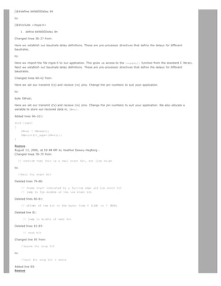
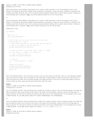
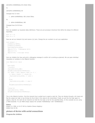
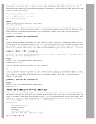


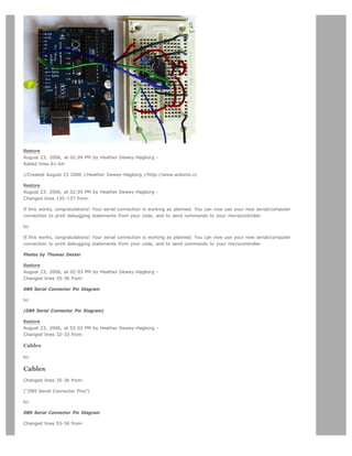
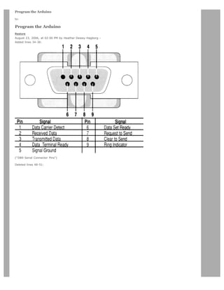
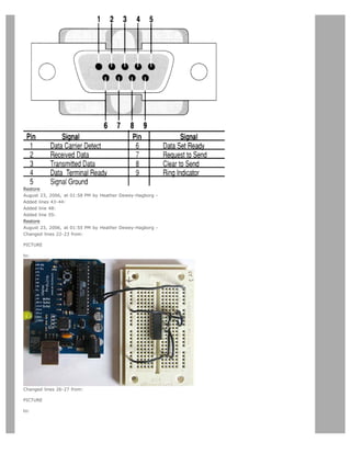
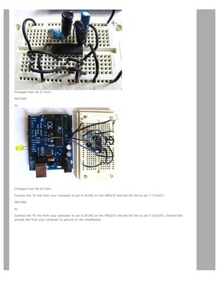
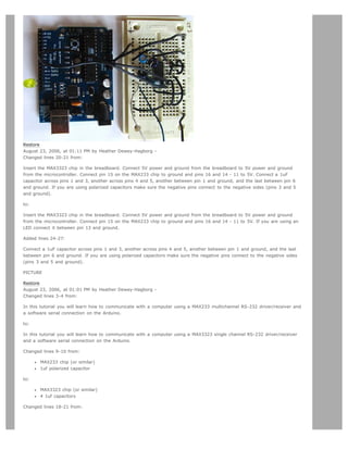
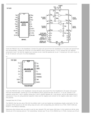
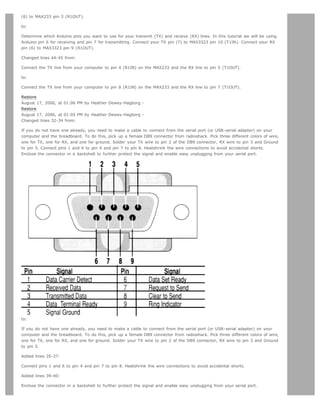
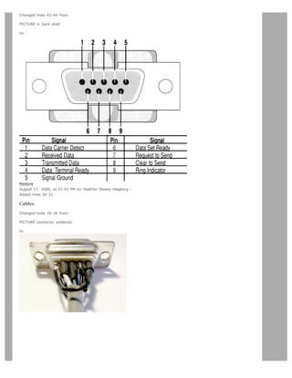
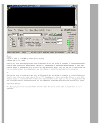
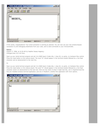
![Restore
August 17, 2006, at 10:19 AM by Heather Dewey-Hagborg -
Changed line 34 from:
PICTURE connector soldered
to:
PICTURE connector soldered, in back shell
Changed lines 110-112 from:
@]
to:
@]
Open up your serial terminal program and set it to 9600 baud, 8 data bits, 1 stop bit, no parity, no hardware flow control.
Press the reset button on the arduino board. The word hi should appear in the terminal window followed by a line feed
character and an advancement to the next line.
Restore
August 17, 2006, at 10:02 AM by Heather Dewey-Hagborg -
Changed lines 30-31 from:
If you do not have one already, you need to make a cable to connect from the serial port (or USB-serial adapter) on your
computer and the breadboard. To do this, pick up a female DB9 connector from radioshack. Pick three different colors of wire,
one for TX, one for RX, and one for ground. Solder your TX wire to pin 2 of the DB9 connector, RX wire to pin 3 and Ground
to pin 5. Connect pins 1 and 6 to pin 4 and pin 7 to pin 8. Heatshrink the wire connections to avoid accidental shorts.
to:
If you do not have one already, you need to make a cable to connect from the serial port (or USB-serial adapter) on your
computer and the breadboard. To do this, pick up a female DB9 connector from radioshack. Pick three different colors of wire,
one for TX, one for RX, and one for ground. Solder your TX wire to pin 2 of the DB9 connector, RX wire to pin 3 and Ground
to pin 5. Connect pins 1 and 6 to pin 4 and pin 7 to pin 8. Heatshrink the wire connections to avoid accidental shorts.
Enclose the connector in a backshell to further protect the signal and enable easy unplugging from your serial port.
Restore
August 17, 2006, at 10:01 AM by Heather Dewey-Hagborg -
Changed line 9 from:](https://image.slidesharecdn.com/arduino-learning-111105084504-phpapp01/85/Arduino-learning-451-320.jpg)
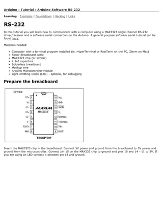
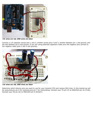
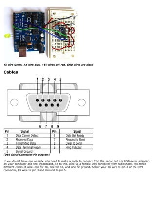
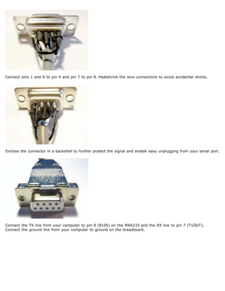
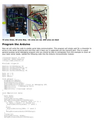
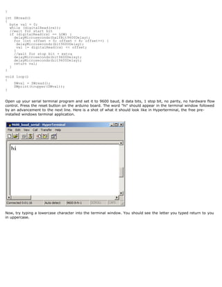
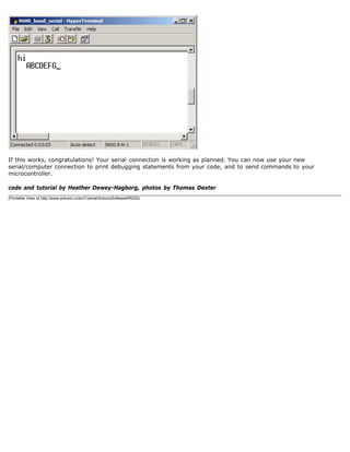

![Arduino search
Buy | Download | Getting Started | Learning | Reference | Hardware | FAQ Blog » | Forum » | Playground »
Tutorial.SPIEEPROM History
Hide minor edits - Show changes to markup
October 07, 2006, at 11:30 AM by Heather Dewey-Hagborg -
Changed lines 16-17 from:
Master In Slave Out (MISO) - The Master line for sending data to the peripherals,
Master Out Slave In (MOSI) - The Slave line for sending data to the master,
to:
Master In Slave Out (MISO) - The Slave line for sending data to the master,
Master Out Slave In (MOSI) - The Master line for sending data to the peripherals,
Restore
September 06, 2006, at 04:30 PM by David A. Mellis - adding note about internal eeprom on arduino
Changed lines 3-4 from:
In this tutorial you will learn how to interface with an AT25HP512 Atmel serial EEPROM using the Serial Peripheral Interface
(SPI) protocol. EEPROM chips such as this are very useful for data storage, and the steps we will cover for implementing SPI
communication can be modified for use with most other SPI devices.
to:
In this tutorial you will learn how to interface with an AT25HP512 Atmel serial EEPROM using the Serial Peripheral Interface
(SPI) protocol. EEPROM chips such as this are very useful for data storage, and the steps we will cover for implementing SPI
communication can be modified for use with most other SPI devices. Note that the chip on the Arduino board contains an
internal EEPROM, so follow this tutorial only if you need more space than it provides.
Restore
September 06, 2006, at 03:38 PM by Heather Dewey-Hagborg -
Changed lines 7-10 from:
1. AT25HP512 Serial EEPROM chip (or similar)
2. Hookup wire
3. Arduino Microcontroller Module
to:
AT25HP512 Serial EEPROM chip (or similar)
Hookup wire
Arduino Microcontroller Module
Restore
September 05, 2006, at 12:57 PM by Heather Dewey-Hagborg -
Changed lines 329-331 from:
@]
to:
@]
code and tutorial by Heather Dewey-Hagborg, photos by Thomas Dexter
Restore
August 31, 2006, at 01:19 PM by Heather Dewey-Hagborg -
Changed lines 70-71 from:](https://image.slidesharecdn.com/arduino-learning-111105084504-phpapp01/85/Arduino-learning-465-320.jpg)
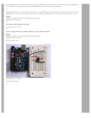
![August 30, 2006, at 11:05 AM by Heather Dewey-Hagborg -
Added lines 78-81:
The first step is setting up our pre-processor directives. Pre-processor directives are processed before the actual compilation
begins. They start with a # and do not end with semi-colons.
We define the pins we will be using for our SPI connection, DATAOUT, DATAIN, SPICLOCK and SLAVESELECT. Then we define
our opcodes for the EEPROM. Opcodes are control commands:
Changed lines 96-99 from:
Here we set up our pre-processor directives. Pre-processor directives are processed before the actual compilation begins.
They start with a # and do not end with semi-colons.
First we define the pins we will be using for our SPI connection, DATAOUT, DATAIN, SPICLOCK and SLAVESELECT. Then we
define our opcodes for the EEPROM. Opcodes are control commands.
to:
Here we allocate the global variables we will be using later in the program. Note char buffer [128];. this is a 128 byte
array we will be using to store the data for the EEPROM write:
Changed lines 106-107 from:
Here we allocate the global variables we will be using later in the program. Note char buffer [128];. this is a 128 byte
array we will be using to store the data for the EEPROM write.
to:
First we initialize our serial connection, set our input and output pin modes and set the SLAVESELECT line high to start. This
deselects the device and avoids any false transmission messages due to line noise:
Changed lines 119-120 from:
First we initialize our serial connection, set our input and output pin modes and set the SLAVESELECT line high to start. This
deselects the device and avoids any false transmission messages due to line noise.
to:
Now we set the SPI Control register (SPCR) to the binary value 01010000. In the control register each bit sets a different
functionality. The eighth bit disables the SPI interrupt, the seventh bit enables the SPI, the sixth bit chooses transmission
with the most significant bit going first, the fifth bit puts the Arduino in Master mode, the fourth bit sets the data clock idle
when it is low, the third bit sets the SPI to sample data on the rising edge of the data clock, and the second and first bits
set the speed of the SPI to system speed / 4 (the fastest). After setting our control register up we read the SPI status
register (SPSR) and data register (SPDR) in to the junk clr variable to clear out any spurious data from past runs:
Changed lines 131-133 from:
Now we set the SPI Control register (SPCR) to the binary value 01010000. In the control register each bit sets a different
functionality. The eighth bit disables the SPI interrupt, the seventh bit enables the SPI, the sixth bit chooses transmission
with the most significant bit going first, the fifth bit puts the Arduino in Master mode, the fourth bit sets the data clock idle
when it is low, the third bit sets the SPI to sample data on the rising edge of the data clock, and the second and first bits
set the speed of the SPI to system speed / 4 (the fastest). After setting our control register up we read the SPI status
register (SPSR) and data register (SPDR) in to the junk clr variabl to clear out any spurious data from past runs.
to:
Here we fill our data array with numbers and send a write enable instruction to the EEPROM. The EEPROM MUST be write
enabled before every write instruction. To send the instruction we pull the SLAVESELECT line low, enabling the device, and
then send the instruction using the spi_transfer function. Note that we use the WREN opcode we defined at the beginning of
the program. Finally we pull the SLAVESELECT line high again to release it:
Changed lines 141-142 from:
Here we fill our data array with numbers and send a write enable instruction to the EEPROM. The EEPROM MUST be write
enabled before every write instruction. To send the instruction we pull the SLAVESELECT line low, enabling the device, and
then send the instruction using the spi_transfer function. Note that we use the WREN opcode we defined at the beginning of
the program. Finally we pull the SLAVESELECT line high again to release it.
to:
Now we pull the SLAVESELECT line low to select the device again after a brief delay. We send a WRITE instruction to tell the](https://image.slidesharecdn.com/arduino-learning-111105084504-phpapp01/85/Arduino-learning-468-320.jpg)
![Restore
August 30, 2006, at 11:01 AM by Heather Dewey-Hagborg -
Changed line 107 from:
void fill_buffer()
to:
void setup()
Deleted lines 108-132:
for (int I=0;I128;I++)
{
buffer[I]=I;
}
} @]
This function simply fills our data array with numbers 0 - 127 for each index in the array. This function could easily be
changed to fill the array with data relevant to your application.
char spi_transfer(volatile char data)
{
SPDR = data; // Start the transmission
while (!(SPSR (1SPIF))) // Wait for the end of the transmission
{
};
return SPDR; // return the received byte
}
This function loads the output data into the data transmission register, thus starting the SPI transmission. It polls a bit to the
SPI Status register (SPSR) to detect when the transmission is complete using a bit mask, SPIF. An explanation of bit masks
can be found here. It then returns any data that has been shifted in to the data register by the EEPROM.
The following setup function is long so we will take it in parts.
[@ void setup() {
Changed lines 163-164 from:
delay(1000);@]
to:
delay(1000);
}@]
Changed line 169 from:
byte read_eeprom(int EEPROM_address)
to:
void loop()
Changed lines 171-179 from:
//READ EEPROM
int data;
digitalWrite(SLAVESELECT,LOW);
spi_transfer(READ); //transmit read opcode
spi_transfer((char)(EEPROM_address8)); //send MSByte address first
spi_transfer((char)(EEPROM_address)); //send LSByte address
data = spi_transfer(0xFF); //get data byte
digitalWrite(SLAVESELECT,HIGH); //release chip, signal end transfer
return data;
to:
eeprom_output_data = read_eeprom(address);
Serial.print(eeprom_output_data,DEC);](https://image.slidesharecdn.com/arduino-learning-111105084504-phpapp01/85/Arduino-learning-470-320.jpg)
![Serial.print('n',BYTE);
address++;
delay(500); //pause for readability
Changed lines 178-179 from:
This function allows us to read data back out of the EEPROM. First we set the SLAVESELECT line low to enable the device.
Then we transmit a READ instruction, followed by the 16-bit address we wish to read from, Most Significant Bit first. Next we
send a dummy byte to the EEPROM for the purpose of shifting the data out. Finally we pull the SLAVESELECT line high again
to release the device after reading one byte, and return the data. If we wanted to read multiple bytes at a time we could
hold the SLAVESELECT line low while we repeated the data = spi_transfer(0xFF); up to 128 times for a full page of data.
to:
In our main loop we just read one byte at a time from the EEPROM and print it out the serial port. We add a line feed and a
pause for readability. Each time through the loop we increment the eeprom address to read. When the address increments to
128 we turn it back to 0 because we have only filled 128 addresses in the EEPROM with data.
Changed line 181 from:
void loop()
to:
void fill_buffer()
Changed lines 183-187 from:
eeprom_output_data = read_eeprom(address);
Serial.print(eeprom_output_data,DEC);
Serial.print('n',BYTE);
address++;
delay(500); //pause for readability
to:
for (int I=0;I128;I++)
{
buffer[I]=I;
}
Changed lines 189-193 from:
Finally we get to our main loop, the simplest function in the program! Here we just read one byte at a time from the
EEPROM and print it out the serial port. We add a line feed and a pause for readability. Each time through the loop we
increment the eeprom address to read. When the address increments to 128 we turn it back to 0 because we have only filled
128 addresses in the EEPROM with data.
For easy copy and pasting the full program text of this tutorial is below:
to:
This function simply fills our data array with numbers 0 - 127 for each index in the array. This function could easily be
changed to fill the array with data relevant to your application.
Changed lines 192-212 from:
1. define DATAOUT 11//MOSI
2. define DATAIN 12//MISO
3. define SPICLOCK 13//sck
4. define SLAVESELECT 10//ss
//opcodes
1. define WREN 6
2. define WRDI 4
3. define RDSR 5
4. define WRSR 1
5. define READ 3
6. define WRITE 2
byte eeprom_output_data; byte eeprom_input_data=0; byte clr; int address=0; //data buffer char buffer [128];](https://image.slidesharecdn.com/arduino-learning-111105084504-phpapp01/85/Arduino-learning-471-320.jpg)
![void fill_buffer()
to:
char spi_transfer(volatile char data)
Changed lines 194-195 from:
for (int I=0;I128;I++)
to:
SPDR = data; // Start the transmission
while (!(SPSR (1SPIF))) // Wait for the end of the transmission
Deleted lines 196-204:
buffer[I]=I;
}
}
char spi_transfer(volatile char data) {
SPDR = data; // Start the transmission
while (!(SPSR (1SPIF))) // Wait the end of the transmission
{
Changed lines 199-201 from:
}
void setup()
to:
}@]
This function loads the output data into the data transmission register, thus starting the SPI transmission. It polls a bit to the
SPI Status register (SPSR) to detect when the transmission is complete using a bit mask, SPIF. An explanation of bit masks
can be found here. It then returns any data that has been shifted in to the data register by the EEPROM.
[@ byte read_eeprom(int EEPROM_address)
Changed lines 206-222 from:
Serial.begin(9600);
pinMode(DATAOUT, OUTPUT);
pinMode(DATAIN, INPUT);
pinMode(SPICLOCK,OUTPUT);
pinMode(SLAVESELECT,OUTPUT);
digitalWrite(SLAVESELECT,HIGH); //disable device
// SPCR = 01010000
//interrupt disabled,spi enabled,msb 1st,master,clk low when idle,
//sample on leading edge of clk,system clock/4 rate (fastest)
SPCR = (1SPE)|(1MSTR);
clr=SPSR;
clr=SPDR;
delay(10);
//fill buffer with data
fill_buffer();
//fill eeprom w/ buffer
to:
//READ EEPROM
int data;
Deleted lines 208-234:
spi_transfer(WREN); //write enable](https://image.slidesharecdn.com/arduino-learning-111105084504-phpapp01/85/Arduino-learning-472-320.jpg)
![digitalWrite(SLAVESELECT,HIGH);
delay(10);
digitalWrite(SLAVESELECT,LOW);
spi_transfer(WRITE); //write instruction
address=0;
spi_transfer((char)(address8)); //send MSByte address first
spi_transfer((char)(address)); //send LSByte address
//write 128 bytes
for (int I=0;I128;I++)
{
spi_transfer(buffer[I]); //write data byte
}
digitalWrite(SLAVESELECT,HIGH); //release chip
//wait for eeprom to finish writing
delay(3000);
Serial.print('h',BYTE);
Serial.print('i',BYTE);
Serial.print('n',BYTE);//debug
delay(1000);
}
byte read_eeprom(int EEPROM_address) {
//READ EEPROM
int data;
digitalWrite(SLAVESELECT,LOW);
Changed lines 215-228 from:
}
void loop() {
eeprom_output_data = read_eeprom(address);
Serial.print(eeprom_output_data,DEC);
Serial.print('n',BYTE);
address++;
if (address == 128)
address = 0;
delay(500); //pause for readability
} @]
to:
} @]
This function allows us to read data back out of the EEPROM. First we set the SLAVESELECT line low to enable the device.
Then we transmit a READ instruction, followed by the 16-bit address we wish to read from, Most Significant Bit first. Next we
send a dummy byte to the EEPROM for the purpose of shifting the data out. Finally we pull the SLAVESELECT line high again
to release the device after reading one byte, and return the data. If we wanted to read multiple bytes at a time we could
hold the SLAVESELECT line low while we repeated the data = spi_transfer(0xFF); up to 128 times for a full page of data.
For easy copy and pasting the full program text of this tutorial is below:
Added lines 223-327:
1. define DATAOUT 11//MOSI
2. define DATAIN 12//MISO
3. define SPICLOCK 13//sck
4. define SLAVESELECT 10//ss
//opcodes
1. define WREN 6
2. define WRDI 4
3. define RDSR 5
4. define WRSR 1
5. define READ 3](https://image.slidesharecdn.com/arduino-learning-111105084504-phpapp01/85/Arduino-learning-473-320.jpg)
![6. define WRITE 2
byte eeprom_output_data; byte eeprom_input_data=0; byte clr; int address=0; //data buffer char buffer [128];
void fill_buffer() {
for (int I=0;I128;I++)
{
buffer[I]=I;
}
}
char spi_transfer(volatile char data) {
SPDR = data; // Start the transmission
while (!(SPSR (1SPIF))) // Wait the end of the transmission
{
};
return SPDR; // return the received byte
}
void setup() {
Serial.begin(9600);
pinMode(DATAOUT, OUTPUT);
pinMode(DATAIN, INPUT);
pinMode(SPICLOCK,OUTPUT);
pinMode(SLAVESELECT,OUTPUT);
digitalWrite(SLAVESELECT,HIGH); //disable device
// SPCR = 01010000
//interrupt disabled,spi enabled,msb 1st,master,clk low when idle,
//sample on leading edge of clk,system clock/4 rate (fastest)
SPCR = (1SPE)|(1MSTR);
clr=SPSR;
clr=SPDR;
delay(10);
//fill buffer with data
fill_buffer();
//fill eeprom w/ buffer
digitalWrite(SLAVESELECT,LOW);
spi_transfer(WREN); //write enable
digitalWrite(SLAVESELECT,HIGH);
delay(10);
digitalWrite(SLAVESELECT,LOW);
spi_transfer(WRITE); //write instruction
address=0;
spi_transfer((char)(address8)); //send MSByte address first
spi_transfer((char)(address)); //send LSByte address
//write 128 bytes
for (int I=0;I128;I++)
{
spi_transfer(buffer[I]); //write data byte
}
digitalWrite(SLAVESELECT,HIGH); //release chip
//wait for eeprom to finish writing
delay(3000);
Serial.print('h',BYTE);
Serial.print('i',BYTE);
Serial.print('n',BYTE);//debug
delay(1000);
}
byte read_eeprom(int EEPROM_address) {
//READ EEPROM](https://image.slidesharecdn.com/arduino-learning-111105084504-phpapp01/85/Arduino-learning-474-320.jpg)
![int data;
digitalWrite(SLAVESELECT,LOW);
spi_transfer(READ); //transmit read opcode
spi_transfer((char)(EEPROM_address8)); //send MSByte address first
spi_transfer((char)(EEPROM_address)); //send LSByte address
data = spi_transfer(0xFF); //get data byte
digitalWrite(SLAVESELECT,HIGH); //release chip, signal end transfer
return data;
}
void loop() {
eeprom_output_data = read_eeprom(address);
Serial.print(eeprom_output_data,DEC);
Serial.print('n',BYTE);
address++;
if (address == 128)
address = 0;
delay(500); //pause for readability
} @]
[@
Restore
August 30, 2006, at 10:57 AM by Heather Dewey-Hagborg -
Changed lines 53-54 from:
Once you have your SPI Control Register set correctly you just need to figure out how long you need to pause between
instructions and you are ready to go. Now that you have a feel for how SPI works, let's take a look at the EEPROM chip.
to:
Once you have your SPI Control Register set correctly you just need to figure out how long you need to pause between
instructions and you are ready to go. Now that you have a feel for how SPI works, let's take a look at the details of the
EEPROM chip.
Changed lines 62-63 from:
The device is enabled by pulling the Chip Select (CS) pin low. Instructions are 8 bit opcodes and are shifted in on the rising
edge of the data clock. It takes the EEPROM about 10 milliseconds to write a page (128 bytes) of data, so a 10ms pause
should follow each EEPROM write routine.
to:
The device is enabled by pulling the Chip Select (CS) pin low. Instructions are sent as 8 bit operational codes (opcodes) and
are shifted in on the rising edge of the data clock. It takes the EEPROM about 10 milliseconds to write a page (128 bytes) of
data, so a 10ms pause should follow each EEPROM write routine.
Changed lines 127-128 from:
This function loads the output data into the data transmission register, thus starting the SPI transmission. It polls a bit to the
SPI Status register (SPSR) to detect when the transmission is complete. It then returns any data that has been shifted in to
the data register by the EEPROM.
to:
This function loads the output data into the data transmission register, thus starting the SPI transmission. It polls a bit to the
SPI Status register (SPSR) to detect when the transmission is complete using a bit mask, SPIF. An explanation of bit masks
can be found here. It then returns any data that has been shifted in to the data register by the EEPROM.
Changed lines 154-155 from:
After setting our control register up we clear any spurious data from the Status and Control registers.
to:
After setting our control register up we read the SPI status register (SPSR) and data register (SPDR) in to the junk clr variabl
to clear out any spurious data from past runs.
Restore](https://image.slidesharecdn.com/arduino-learning-111105084504-phpapp01/85/Arduino-learning-475-320.jpg)
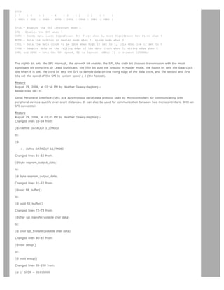
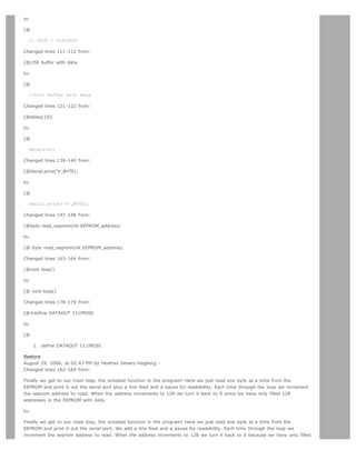
![128 addresses in the EEPROM with data.
Restore
August 29, 2006, at 02:42 PM by Heather Dewey-Hagborg -
Added lines 59-164:
void fill_buffer()
{
for (int I=0;I128;I++)
{
buffer[I]=I;
}
}
This function simply fills our data array with numbers 0 - 127 for each index in the array. This function could easily be
changed to fill the array with data relevant to your application.
char spi_transfer(volatile char data)
{
SPDR = data; // Start the transmission
while (!(SPSR (1SPIF))) // Wait for the end of the transmission
{
};
return SPDR; // return the received byte
}
This function loads the output data into the data transmission register, thus starting the SPI transmission. It polls a bit to the
SPI Status register (SPSR) to detect when the transmission is complete. It then returns any data that has been shifted in to
the data register by the EEPROM.
The following setup function is long so we will take it in parts.
void setup()
{
Serial.begin(9600);
pinMode(DATAOUT, OUTPUT);
pinMode(DATAIN, INPUT);
pinMode(SPICLOCK,OUTPUT);
pinMode(SLAVESELECT,OUTPUT);
digitalWrite(SLAVESELECT,HIGH); //disable device
First we initialize our serial connection, set our input and output pin modes and set the SLAVESELECT line high to start. This
deselects the device and avoids any false transmission messages due to line noise.
// SPCR = 01010000
//interrupt disabled,spi enabled,msb 1st,master,clk low when idle,
//sample on leading edge of clk,system clock/4 rate (fastest)
SPCR = (1SPE)|(1MSTR);
clr=SPSR;
clr=SPDR;
delay(10);
Now we set the SPI Control register (SPCR) to the binary value 01010000. In the control register each bit sets a different
functionality. The eighth bit disables the SPI interrupt, the seventh bit enables the SPI, the sixth bit chooses transmission
with the most significant bit going first, the fifth bit puts the Arduino in Master mode, the fourth bit sets the data clock idle
when it is low, the third bit sets the SPI to sample data on the rising edge of the data clock, and the second and first bits
set the speed of the SPI to system speed / 4 (the fastest). After setting our control register up we clear any spurious data
from the Status and Control registers.
//fill buffer with data
fill_buffer();
//fill eeprom w/ buffer
digitalWrite(SLAVESELECT,LOW);
spi_transfer(WREN); //write enable
digitalWrite(SLAVESELECT,HIGH);
Here we fill our data array with numbers and send a write enable instruction to the EEPROM. The EEPROM MUST be write
enabled before every write instruction. To send the instruction we pull the SLAVESELECT line low, enabling the device, and](https://image.slidesharecdn.com/arduino-learning-111105084504-phpapp01/85/Arduino-learning-480-320.jpg)
![then send the instruction using the spi_transfer function. Note that we use the WREN opcode we defined at the beginning of
the program. Finally we pull the SLAVESELECT line high again to release it.
delay(10);
digitalWrite(SLAVESELECT,LOW);
spi_transfer(WRITE); //write instruction
address=0;
spi_transfer((char)(address8)); //send MSByte address first
spi_transfer((char)(address)); //send LSByte address
//write 128 bytes
for (int I=0;I128;I++)
{
spi_transfer(buffer[I]); //write data byte
}
digitalWrite(SLAVESELECT,HIGH); //release chip
//wait for eeprom to finish writing
delay(3000);
Now we pull the SLAVESELECT line low to select the device again after a brief delay. We send a WRITE instruction to tell the
EEPROM we will be sending data to record into memory. We send the 16 bit address to begin writing at in two bytes, Most
Significant Bit first. Next we send our 128 bytes of data from our buffer array, one byte after another without pause. Finally
we set the SLAVESELECT pin high to release the device and pause to allow the EEPROM to write the data.
Serial.print('h',BYTE);
Serial.print('i',BYTE);
Serial.print('n',BYTE);//debug
delay(1000);
We end the setup function by sending the word hi plus a line feed out the built in serial port for debugging purposes. This
way if our data comes out looking funny later on we can tell it isn't just the serial port acting up.
byte read_eeprom(int EEPROM_address)
{
//READ EEPROM
int data;
digitalWrite(SLAVESELECT,LOW);
spi_transfer(READ); //transmit read opcode
spi_transfer((char)(EEPROM_address8)); //send MSByte address first
spi_transfer((char)(EEPROM_address)); //send LSByte address
data = spi_transfer(0xFF); //get data byte
digitalWrite(SLAVESELECT,HIGH); //release chip, signal end transfer
return data;
}
This function allows us to read data back out of the EEPROM. First we set the SLAVESELECT line low to enable the device.
Then we transmit a READ instruction, followed by the 16-bit address we wish to read from, Most Significant Bit first. Next we
send a dummy byte to the EEPROM for the purpose of shifting the data out. Finally we pull the SLAVESELECT line high again
to release the device after reading one byte, and return the data. If we wanted to read multiple bytes at a time we could
hold the SLAVESELECT line low while we repeated the data = spi_transfer(0xFF); up to 128 times for a full page of data.
void loop()
{
eeprom_output_data = read_eeprom(address);
Serial.print(eeprom_output_data,DEC);
Serial.print('n',BYTE);
address++;
delay(500); //pause for readability
}
Finally we get to our main loop, the simplest function in the program! Here we just read one byte at a time from the
EEPROM and print it out the serial port plus a line feed and a pause for readability. Each time through the loop we increment
the eeprom address to read. When the address increments to 128 we turn it back to 0 since we have only filled 128
addresses in the EEPROM with data.
Added lines 166-270:
#define DATAOUT 11//MOSI
#define DATAIN 12//MISO](https://image.slidesharecdn.com/arduino-learning-111105084504-phpapp01/85/Arduino-learning-481-320.jpg)
![#define SPICLOCK 13//sck
#define SLAVESELECT 10//ss
//opcodes
#define WREN 6
#define WRDI 4
#define RDSR 5
#define WRSR 1
#define READ 3
#define WRITE 2
byte eeprom_output_data;
byte eeprom_input_data=0;
byte clr;
int address=0;
//data buffer
char buffer [128];
void fill_buffer()
{
for (int I=0;I128;I++)
{
buffer[I]=I;
}
}
char spi_transfer(volatile char data)
{
SPDR = data; // Start the transmission
while (!(SPSR (1SPIF))) // Wait the end of the transmission
{
};
return SPDR; // return the received byte
}
void setup()
{
Serial.begin(9600);
pinMode(DATAOUT, OUTPUT);
pinMode(DATAIN, INPUT);
pinMode(SPICLOCK,OUTPUT);
pinMode(SLAVESELECT,OUTPUT);
digitalWrite(SLAVESELECT,HIGH); //disable device
// SPCR = 01010000
//interrupt disabled,spi enabled,msb 1st,master,clk low when idle,
//sample on leading edge of clk,system clock/4 rate (fastest)
SPCR = (1SPE)|(1MSTR);
clr=SPSR;
clr=SPDR;
delay(10);
//fill buffer with data
fill_buffer();
//fill eeprom w/ buffer
digitalWrite(SLAVESELECT,LOW);
spi_transfer(WREN); //write enable
digitalWrite(SLAVESELECT,HIGH);
delay(10);
digitalWrite(SLAVESELECT,LOW);
spi_transfer(WRITE); //write instruction
address=0;
spi_transfer((char)(address8)); //send MSByte address first
spi_transfer((char)(address)); //send LSByte address
//write 128 bytes
for (int I=0;I128;I++)](https://image.slidesharecdn.com/arduino-learning-111105084504-phpapp01/85/Arduino-learning-482-320.jpg)
![{
spi_transfer(buffer[I]); //write data byte
}
digitalWrite(SLAVESELECT,HIGH); //release chip
//wait for eeprom to finish writing
delay(3000);
Serial.print('h',BYTE);
Serial.print('i',BYTE);
Serial.print('n',BYTE);//debug
delay(1000);
}
byte read_eeprom(int EEPROM_address)
{
//READ EEPROM
int data;
digitalWrite(SLAVESELECT,LOW);
spi_transfer(READ); //transmit read opcode
spi_transfer((char)(EEPROM_address8)); //send MSByte address first
spi_transfer((char)(EEPROM_address)); //send LSByte address
data = spi_transfer(0xFF); //get data byte
digitalWrite(SLAVESELECT,HIGH); //release chip, signal end transfer
return data;
}
void loop()
{
eeprom_output_data = read_eeprom(address);
Serial.print(eeprom_output_data,DEC);
Serial.print('n',BYTE);
address++;
if (address == 128)
address = 0;
delay(500); //pause for readability
}
Restore
August 29, 2006, at 01:15 PM by Heather Dewey-Hagborg -
Added lines 30-61:
Now we will write the code to enable SPI communication between the EEPROM and the Arduino. In the setup routine this
program fills 128 bytes, or one page of the EEPROM with data. In the main loop it reads that data back out, one byte at a
time and prints that byte out the built in serial port. We will walk through the code in small sections.
#define DATAOUT 11//MOSI
#define DATAIN 12//MISO
#define SPICLOCK 13//sck
#define SLAVESELECT 10//ss
//opcodes
#define WREN 6
#define WRDI 4
#define RDSR 5
#define WRSR 1
#define READ 3
#define WRITE 2
Here we set up our pre-processor directives. Pre-processor directives are processed before the actual compilation begins.
They start with a # and do not end with semi-colons.
First we define the pins we will be using for our SPI connection, DATAOUT, DATAIN, SPICLOCK and SLAVESELECT. Then we
define our opcodes for the EEPROM. Opcodes are control commands.
byte eeprom_output_data;
byte eeprom_input_data=0;](https://image.slidesharecdn.com/arduino-learning-111105084504-phpapp01/85/Arduino-learning-483-320.jpg)
![byte clr;
int address=0;
//data buffer
char buffer [128];
Here we allocate the global variables we will be using later in the program. Note char buffer [128];. this is a 128 byte
array we will be using to store the data for the EEPROM write.
For easy copy and pasting the full program text of this tutorial is below:
Restore
August 29, 2006, at 12:58 PM by Heather Dewey-Hagborg -
Added lines 21-28:
Insert the AT25HP512 chip into the breadboard. Connect 5V power and ground from the breadboard to 5V power and ground
from the microcontroller. Connect EEPROM pins 3, 7 and 8 to 5v and pin 4 to ground.
PICTURE of pwr wires
Connect EEPROM pin 1 to Arduino pin 10 (Slave Select), EEPROM pin 2 to Arduino pin 12 (Master In Slave Out), EEPROM pin
5 to Arduino pin 11 (Master Out Slave In), and EEPROM pin 6 to Arduino pin 13 (Serial Clock).
PICTURE of SPI wires
Restore
August 27, 2006, at 01:17 PM by Heather Dewey-Hagborg -
Changed line 1 from:
Interfacing a serial EEPROM using SPI
to:
Interfacing a Serial EEPROM Using SPI
Changed lines 12-15 from:
Serial Peripheral Interface
Atmel 25HP512 EEPROM chip
to:
Introduction to the Serial Peripheral Interface
Introduction to Serial EEPROM
Restore
August 27, 2006, at 01:14 PM by Heather Dewey-Hagborg -
Added lines 14-18:
Atmel 25HP512 EEPROM chip](https://image.slidesharecdn.com/arduino-learning-111105084504-phpapp01/85/Arduino-learning-484-320.jpg)
![#define DATAIN 12//MISO
#define SPICLOCK 13//sck
#define SLAVESELECT 10//ss
//opcodes
#define WREN 6
#define WRDI 4
#define RDSR 5
#define WRSR 1
#define READ 3
#define WRITE 2
Here we allocate the global variables we will be using later in the program. Note char buffer [128];. this is a
128 byte array we will be using to store the data for the EEPROM write:
byte eeprom_output_data;
byte eeprom_input_data=0;
byte clr;
int address=0;
//data buffer
char buffer [128];
First we initialize our serial connection, set our input and output pin modes and set the SLAVESELECT line high to
start. This deselects the device and avoids any false transmission messages due to line noise:
void setup()
{
Serial.begin(9600);
pinMode(DATAOUT, OUTPUT);
pinMode(DATAIN, INPUT);
pinMode(SPICLOCK,OUTPUT);
pinMode(SLAVESELECT,OUTPUT);
digitalWrite(SLAVESELECT,HIGH); //disable device
Now we set the SPI Control register (SPCR) to the binary value 01010000. In the control register each bit sets a
different functionality. The eighth bit disables the SPI interrupt, the seventh bit enables the SPI, the sixth bit
chooses transmission with the most significant bit going first, the fifth bit puts the Arduino in Master mode, the
fourth bit sets the data clock idle when it is low, the third bit sets the SPI to sample data on the rising edge of the
data clock, and the second and first bits set the speed of the SPI to system speed / 4 (the fastest). After setting
our control register up we read the SPI status register (SPSR) and data register (SPDR) in to the junk clr variable
to clear out any spurious data from past runs:
// SPCR = 01010000
//interrupt disabled,spi enabled,msb 1st,master,clk low when idle,
//sample on leading edge of clk,system clock/4 rate (fastest)
SPCR = (1SPE)|(1MSTR);
clr=SPSR;
clr=SPDR;
delay(10);
Here we fill our data array with numbers and send a write enable instruction to the EEPROM. The EEPROM MUST
be write enabled before every write instruction. To send the instruction we pull the SLAVESELECT line low, enabling
the device, and then send the instruction using the spi_transfer function. Note that we use the WREN opcode we
defined at the beginning of the program. Finally we pull the SLAVESELECT line high again to release it:
//fill buffer with data
fill_buffer();
//fill eeprom w/ buffer
digitalWrite(SLAVESELECT,LOW);
spi_transfer(WREN); //write enable
digitalWrite(SLAVESELECT,HIGH);
Now we pull the SLAVESELECT line low to select the device again after a brief delay. We send a WRITE instruction
to tell the EEPROM we will be sending data to record into memory. We send the 16 bit address to begin writing at
in two bytes, Most Significant Bit first. Next we send our 128 bytes of data from our buffer array, one byte after
another without pause. Finally we set the SLAVESELECT pin high to release the device and pause to allow the
EEPROM to write the data:](https://image.slidesharecdn.com/arduino-learning-111105084504-phpapp01/85/Arduino-learning-489-320.jpg)
![delay(10);
digitalWrite(SLAVESELECT,LOW);
spi_transfer(WRITE); //write instruction
address=0;
spi_transfer((char)(address8)); //send MSByte address first
spi_transfer((char)(address)); //send LSByte address
//write 128 bytes
for (int I=0;I128;I++)
{
spi_transfer(buffer[I]); //write data byte
}
digitalWrite(SLAVESELECT,HIGH); //release chip
//wait for eeprom to finish writing
delay(3000);
We end the setup function by sending the word hi plus a line feed out the built in serial port for debugging
purposes. This way if our data comes out looking funny later on we can tell it isn't just the serial port acting up:
Serial.print('h',BYTE);
Serial.print('i',BYTE);
Serial.print('n',BYTE);//debug
delay(1000);
}
In our main loop we just read one byte at a time from the EEPROM and print it out the serial port. We add a line
feed and a pause for readability. Each time through the loop we increment the eeprom address to read. When the
address increments to 128 we turn it back to 0 because we have only filled 128 addresses in the EEPROM with
data:
void loop()
{
eeprom_output_data = read_eeprom(address);
Serial.print(eeprom_output_data,DEC);
Serial.print('n',BYTE);
address++;
delay(500); //pause for readability
}
The fill_buffer function simply fills our data array with numbers 0 - 127 for each index in the array. This function
could easily be changed to fill the array with data relevant to your application:
void fill_buffer()
{
for (int I=0;I128;I++)
{
buffer[I]=I;
}
}
The spi_transfer function loads the output data into the data transmission register, thus starting the SPI
transmission. It polls a bit to the SPI Status register (SPSR) to detect when the transmission is complete using a
bit mask, SPIF. An explanation of bit masks can be found here. It then returns any data that has been shifted in to
the data register by the EEPROM:
char spi_transfer(volatile char data)
{
SPDR = data; // Start the transmission
while (!(SPSR (1SPIF))) // Wait for the end of the transmission
{
};
return SPDR; // return the received byte
}
The read_eeprom function allows us to read data back out of the EEPROM. First we set the SLAVESELECT line low
to enable the device. Then we transmit a READ instruction, followed by the 16-bit address we wish to read from,
Most Significant Bit first. Next we send a dummy byte to the EEPROM for the purpose of shifting the data out.
Finally we pull the SLAVESELECT line high again to release the device after reading one byte, and return the data.
If we wanted to read multiple bytes at a time we could hold the SLAVESELECT line low while we repeated the
data = spi_transfer(0xFF); up to 128 times for a full page of data:
byte read_eeprom(int EEPROM_address)
{](https://image.slidesharecdn.com/arduino-learning-111105084504-phpapp01/85/Arduino-learning-490-320.jpg)
![//READ EEPROM
int data;
digitalWrite(SLAVESELECT,LOW);
spi_transfer(READ); //transmit read opcode
spi_transfer((char)(EEPROM_address8)); //send MSByte address first
spi_transfer((char)(EEPROM_address)); //send LSByte address
data = spi_transfer(0xFF); //get data byte
digitalWrite(SLAVESELECT,HIGH); //release chip, signal end transfer
return data;
}
For easy copy and pasting the full program text of this tutorial is below:
#define DATAOUT 11//MOSI
#define DATAIN 12//MISO
#define SPICLOCK 13//sck
#define SLAVESELECT 10//ss
//opcodes
#define WREN 6
#define WRDI 4
#define RDSR 5
#define WRSR 1
#define READ 3
#define WRITE 2
byte eeprom_output_data;
byte eeprom_input_data=0;
byte clr;
int address=0;
//data buffer
char buffer [128];
void fill_buffer()
{
for (int I=0;I128;I++)
{
buffer[I]=I;
}
}
char spi_transfer(volatile char data)
{
SPDR = data; // Start the transmission
while (!(SPSR (1SPIF))) // Wait the end of the transmission
{
};
return SPDR; // return the received byte
}
void setup()
{
Serial.begin(9600);
pinMode(DATAOUT, OUTPUT);
pinMode(DATAIN, INPUT);
pinMode(SPICLOCK,OUTPUT);
pinMode(SLAVESELECT,OUTPUT);
digitalWrite(SLAVESELECT,HIGH); //disable device
// SPCR = 01010000
//interrupt disabled,spi enabled,msb 1st,master,clk low when idle,
//sample on leading edge of clk,system clock/4 rate (fastest)
SPCR = (1SPE)|(1MSTR);
clr=SPSR;
clr=SPDR;
delay(10);
//fill buffer with data
fill_buffer();
//fill eeprom w/ buffer
digitalWrite(SLAVESELECT,LOW);
spi_transfer(WREN); //write enable
digitalWrite(SLAVESELECT,HIGH);
delay(10);
digitalWrite(SLAVESELECT,LOW);
spi_transfer(WRITE); //write instruction
address=0;
spi_transfer((char)(address8)); //send MSByte address first
spi_transfer((char)(address)); //send LSByte address
//write 128 bytes](https://image.slidesharecdn.com/arduino-learning-111105084504-phpapp01/85/Arduino-learning-491-320.jpg)
![for (int I=0;I128;I++)
{
spi_transfer(buffer[I]); //write data byte
}
digitalWrite(SLAVESELECT,HIGH); //release chip
//wait for eeprom to finish writing
delay(3000);
Serial.print('h',BYTE);
Serial.print('i',BYTE);
Serial.print('n',BYTE);//debug
delay(1000);
}
byte read_eeprom(int EEPROM_address)
{
//READ EEPROM
int data;
digitalWrite(SLAVESELECT,LOW);
spi_transfer(READ); //transmit read opcode
spi_transfer((char)(EEPROM_address8)); //send MSByte address first
spi_transfer((char)(EEPROM_address)); //send LSByte address
data = spi_transfer(0xFF); //get data byte
digitalWrite(SLAVESELECT,HIGH); //release chip, signal end transfer
return data;
}
void loop()
{
eeprom_output_data = read_eeprom(address);
Serial.print(eeprom_output_data,DEC);
Serial.print('n',BYTE);
address++;
if (address == 128)
address = 0;
delay(500); //pause for readability
}
code and tutorial by Heather Dewey-Hagborg, photos by Thomas Dexter
(Printable View of http://www.arduino.cc/en/Tutorial/SPIEEPROM)](https://image.slidesharecdn.com/arduino-learning-111105084504-phpapp01/85/Arduino-learning-492-320.jpg)

![Arduino search
Buy | Download | Getting Started | Learning | Reference | Hardware | FAQ Blog » | Forum » | Playground »
Tutorial.SPIDigitalPot History
Hide minor edits - Show changes to markup
September 06, 2006, at 04:02 PM by Heather Dewey-Hagborg -
Changed lines 137-138 from:
VIDEO ? LEDs
to:
LED video
Restore
September 06, 2006, at 03:55 PM by Heather Dewey-Hagborg -
Changed lines 204-206 from:
@]
to:
@]
code, tutorial and photos by Heather Dewey-Hagborg
Restore
September 06, 2006, at 03:49 PM by Heather Dewey-Hagborg -
Changed lines 28-29 from:
PICTURE power
to:
Changed lines 32-33 from:
PICTURE datacom
to:](https://image.slidesharecdn.com/arduino-learning-111105084504-phpapp01/85/Arduino-learning-494-320.jpg)
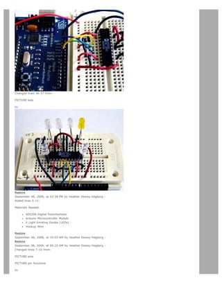
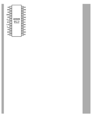
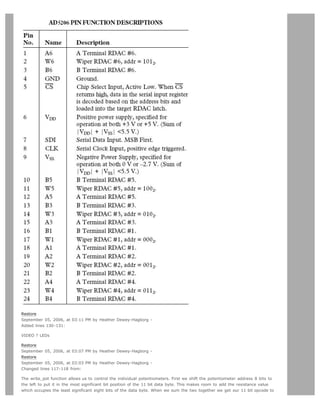
![transmit:
to:
The write_pot function allows us to control the individual potentiometers. We set the SLAVESELECT line low to enable the
device. Then we transfer the address byte followed by the resistance value byte. Finally, we set the SLAVSELECT line high
again to release the chip and signal the end of our data transfer.
Deleted lines 121-128:
int opcode=0;
address=8; //shift pot address 8 left, ie. 101 = 10100000000
opcode = address+value; //10111111111
@]
We set the SLAVESELECT line low to enable the device. Then we transfer the 11 bit opcode in two bytes sending the eight
most significant bits first and sending the three least significant bits last. We set the SLAVSELECT line high again to release
the chip and signal the end of our data transfer.
[@
Changed lines 124-125 from:
spi_transfer((char)(opcode8)); //send MSByte address first a0a1a2d0d1d2d3d4
spi_transfer((char)(opcode)); //send LSByte address, d5d6d700000
to:
spi_transfer(address);
spi_transfer(value);
Deleted lines 173-175:
int opcode=0;
address=8; //shift pot address 8 left, ie. 101 = 10100000000
opcode = address+value; //10111111111
Changed lines 176-177 from:
spi_transfer((char)(opcode8)); //send MSByte address first a0a1a2d0d1d2d3d4
spi_transfer((char)(opcode)); //send LSByte address, d5d6d700000
to:
spi_transfer(address);
spi_transfer(value);
Restore
September 05, 2006, at 02:42 PM by Heather Dewey-Hagborg -
Changed lines 11-12 from:
The AD5206 is a 6 channel digital potentiometer. This means it has six variable resistors built in for individual electronic
control. There are three pins on the chip for each of the six internal variable resistors, and they can be interfaced with just as
you would use a mechanical potentiometer. The individual variable resistor pins are labeled Ax, Bx and Wx, ie. A1, B1 and
W1.
to:
The AD5206 is a 6 channel digital potentiometer. This means it has six variable resistors (potentiometers) built in for
individual electronic control. There are three pins on the chip for each of the six internal variable resistors, and they can be
interfaced with just as you would use a mechanical potentiometer. The individual variable resistor pins are labeled Ax, Bx and
Wx, ie. A1, B1 and W1.
Changed lines 85-86 from:
The spi_transfer function loads the output data into the data transmission register, thus starting the SPI transmission. It polls
a bit to the SPI Status register (SPSR) to detect when the transmission is complete using a bit mask, SPIF. An explanation of
bit masks can be found here?. It then returns any data that has been shifted in to the data register by the EEPROM:
to:
In our main loop we iterate through each resistance value (0-255) for each potentiometer address (0-5). We pause for 10](https://image.slidesharecdn.com/arduino-learning-111105084504-phpapp01/85/Arduino-learning-498-320.jpg)
![milliseconds each iteration to make the steps visible. This causes the LEDs to sequentially flash on brightly and then fade out
slowly:
Changed line 88 from:
char spi_transfer(volatile char data)
to:
void loop()
Changed lines 90-94 from:
SPDR = data; // Start the transmission
while (!(SPSR (1SPIF))) // Wait the end of the transmission
{
};
return SPDR; // return the received byte
to:
write_pot(pot,resistance);
delay(10);
resistance++;
if (resistance==255)
{
pot++;
}
if (pot==6)
{
pot=0;
}
Added lines 102-205:
@]
The spi_transfer function loads the output data into the data transmission register, thus starting the SPI transmission. It polls
a bit to the SPI Status register (SPSR) to detect when the transmission is complete using a bit mask, SPIF. An explanation of
bit masks can be found here. It then returns any data that has been shifted in to the data register by the EEPROM:
char spi_transfer(volatile char data)
{
SPDR = data; // Start the transmission
while (!(SPSR (1SPIF))) // Wait the end of the transmission
{
};
return SPDR; // return the received byte
}
The write_pot function allows us to control the individual potentiometers. First we shift the potentiometer address 8 bits to
the left to put it in the most significant bit position of the 11 bit data byte. This makes room to add the resistance value
which occupies the least significant eight bits of the data byte. When we sum the two together we get our 11 bit opcode to
transmit:
byte write_pot(int address, int value)
{
int opcode=0;
address=8; //shift pot address 8 left, ie. 101 = 10100000000
opcode = address+value; //10111111111
We set the SLAVESELECT line low to enable the device. Then we transfer the 11 bit opcode in two bytes sending the eight
most significant bits first and sending the three least significant bits last. We set the SLAVSELECT line high again to release
the chip and signal the end of our data transfer.
digitalWrite(SLAVESELECT,LOW);
//2 byte opcode
spi_transfer((char)(opcode8)); //send MSByte address first a0a1a2d0d1d2d3d4](https://image.slidesharecdn.com/arduino-learning-111105084504-phpapp01/85/Arduino-learning-499-320.jpg)
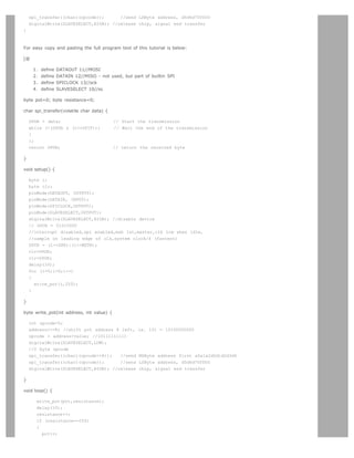
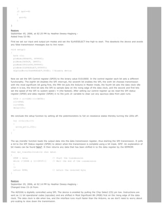
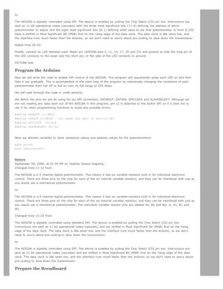
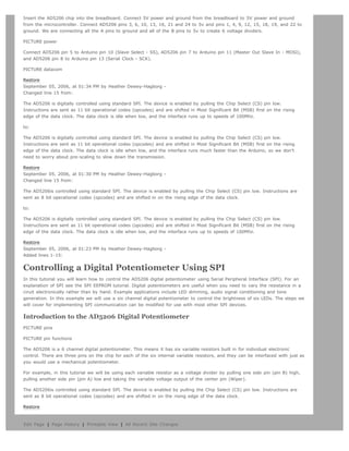

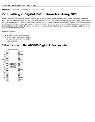
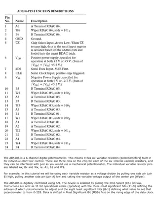
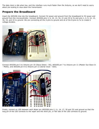
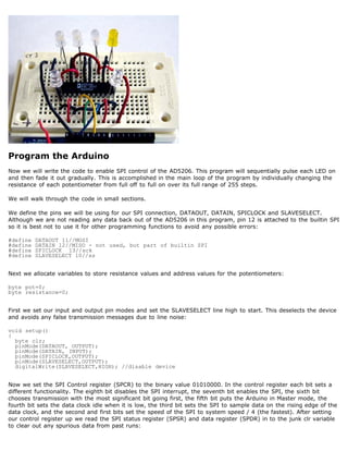
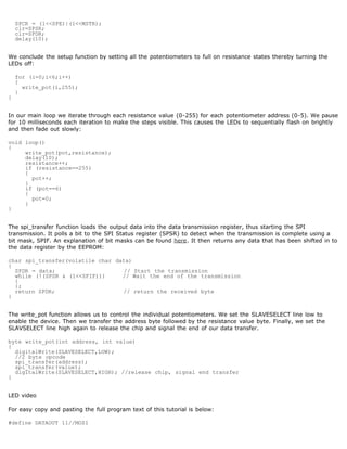
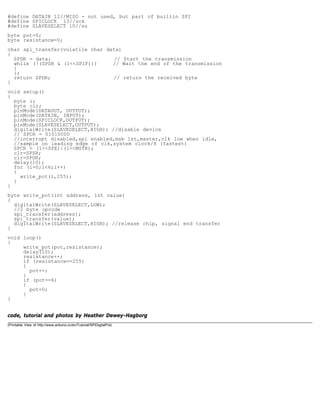

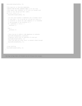
![Arduino search
Buy | Download | Getting Started | Learning | Reference | Hardware | FAQ Blog » | Forum » | Playground »
Learning Examples | Foundations | Hacking | Links
Back to ShiftOut Tutorial
//**************************************************************//
// Name : shiftOutCode, Predefined Array Style //
// Author : Carlyn Maw, Tom Igoe //
// Date : 25 Oct, 2006 //
// Version : 1.0 //
// Notes : Code for using a 74HC595 Shift Register //
// : to count from 0 to 255 //
//****************************************************************
//Pin connected to ST_CP of 74HC595
int latchPin = 8;
//Pin connected to SH_CP of 74HC595
int clockPin = 12;
////Pin connected to DS of 74HC595
int dataPin = 11;
//holders for infromation you're going to pass to shifting function
byte data;
byte dataArray[10];
void setup() {
//set pins to output because they are addressed in the main loop
pinMode(latchPin, OUTPUT);
Serial.begin(9600);
//Arduino doesn't seem to have a way to write binary straight into the code
//so these values are in HEX. Decimal would have been fine, too.
dataArray[0] = 0xAA; //10101010
dataArray[1] = 0x55; //01010101
dataArray[2] = 0x81; //10000001
dataArray[3] = 0xC3; //11000011
dataArray[4] = 0xE7; //11100111
dataArray[5] = 0xFF; //11111111
dataArray[6] = 0x7E; //01111110
dataArray[7] = 0x3C; //00111100
dataArray[8] = 0x18; //00011000
dataArray[9] = 0x00; //00000000
//function that blinks all the LEDs
//gets passed the number of blinks and the pause time
blinkAll(2,500);
}
void loop() {
for (int j = 0; j 10; j++) {
//load the light sequence you want from array
data = dataArray[j];
//ground latchPin and hold low for as long as you are transmitting
digitalWrite(latchPin, 0);](https://image.slidesharecdn.com/arduino-learning-111105084504-phpapp01/85/Arduino-learning-516-320.jpg)
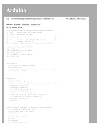
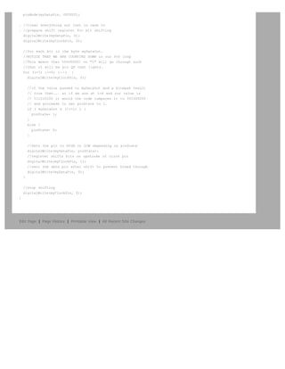

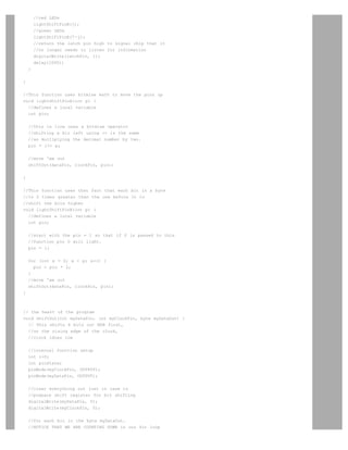
![Arduino search
Buy | Download | Getting Started | Learning | Reference | Hardware | FAQ Blog » | Forum » | Playground »
Learning Examples | Foundations | Hacking | Links
Back to ShiftOut Tutorial
//**************************************************************//
// Name : shiftOutCode, Predefined Dual Array Style //
// Author : Carlyn Maw, Tom Igoe //
// Date : 25 Oct, 2006 //
// Version : 1.0 //
// Notes : Code for using a 74HC595 Shift Register //
// : to count from 0 to 255 //
//****************************************************************
//Pin connected to ST_CP of 74HC595
int latchPin = 8;
//Pin connected to SH_CP of 74HC595
int clockPin = 12;
////Pin connected to DS of 74HC595
int dataPin = 11;
//holders for infromation you're going to pass to shifting function
byte dataRED;
byte dataGREEN;
byte dataArrayRED[10];
byte dataArrayGREEN[10];
void setup() {
//set pins to output because they are addressed in the main loop
pinMode(latchPin, OUTPUT);
Serial.begin(9600);
//Arduino doesn't seem to have a way to write binary straight into the code
//so these values are in HEX. Decimal would have been fine, too.
dataArrayRED[0] = 0xFF; //11111111
dataArrayRED[1] = 0xFE; //11111110
dataArrayRED[2] = 0xFC; //11111100
dataArrayRED[3] = 0xF8; //11111000
dataArrayRED[4] = 0xF0; //11110000
dataArrayRED[5] = 0xE0; //11100000
dataArrayRED[6] = 0xC0; //11000000
dataArrayRED[7] = 0x80; //10000000
dataArrayRED[8] = 0x00; //00000000
dataArrayRED[9] = 0xE0; //11100000
//Arduino doesn't seem to have a way to write binary straight into the code
//so these values are in HEX. Decimal would have been fine, too.
dataArrayGREEN[0] = 0xFF; //11111111
dataArrayGREEN[1] = 0x7F; //01111111
dataArrayGREEN[2] = 0x3F; //00111111
dataArrayGREEN[3] = 0x1F; //00011111
dataArrayGREEN[4] = 0x0F; //00001111
dataArrayGREEN[5] = 0x07; //00000111
dataArrayGREEN[6] = 0x03; //00000011
dataArrayGREEN[7] = 0x01; //00000001
dataArrayGREEN[8] = 0x00; //00000000](https://image.slidesharecdn.com/arduino-learning-111105084504-phpapp01/85/Arduino-learning-524-320.jpg)
![dataArrayGREEN[9] = 0x07; //00000111
//function that blinks all the LEDs
//gets passed the number of blinks and the pause time
blinkAll_2Bytes(2,500);
}
void loop() {
for (int j = 0; j 10; j++) {
//load the light sequence you want from array
dataRED = dataArrayRED[j];
dataGREEN = dataArrayGREEN[j];
//ground latchPin and hold low for as long as you are transmitting
digitalWrite(latchPin, 0);
//move 'em out
shiftOut(dataPin, clockPin, dataGREEN);
shiftOut(dataPin, clockPin, dataRED);
//return the latch pin high to signal chip that it
//no longer needs to listen for information
digitalWrite(latchPin, 1);
delay(300);
}
}
// the heart of the program
void shiftOut(int myDataPin, int myClockPin, byte myDataOut) {
// This shifts 8 bits out MSB first,
//on the rising edge of the clock,
//clock idles low
//internal function setup
int i=0;
int pinState;
pinMode(myClockPin, OUTPUT);
pinMode(myDataPin, OUTPUT);
//clear everything out just in case to
//prepare shift register for bit shifting
digitalWrite(myDataPin, 0);
digitalWrite(myClockPin, 0);
//for each bit in the byte myDataOut…
//NOTICE THAT WE ARE COUNTING DOWN in our for loop
//This means that %00000001 or 1 will go through such
//that it will be pin Q0 that lights.
for (i=7; i=0; i--) {
digitalWrite(myClockPin, 0);
//if the value passed to myDataOut and a bitmask result
// true then... so if we are at i=6 and our value is
// %11010100 it would the code compares it to %01000000
// and proceeds to set pinState to 1.
if ( myDataOut (1i) ) {
pinState= 1;
}
else {
pinState= 0;
}
//Sets the pin to HIGH or LOW depending on pinState
digitalWrite(myDataPin, pinState);](https://image.slidesharecdn.com/arduino-learning-111105084504-phpapp01/85/Arduino-learning-525-320.jpg)

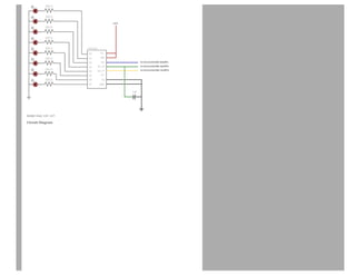
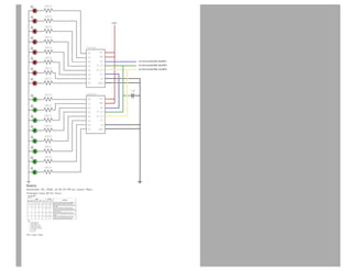
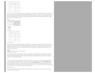
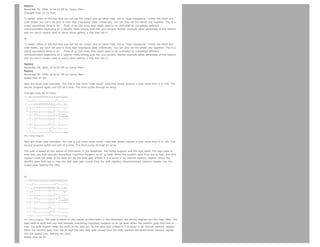
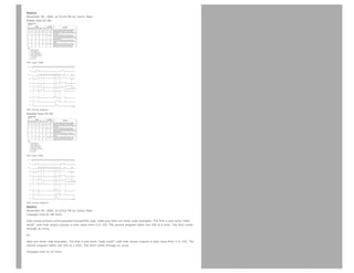

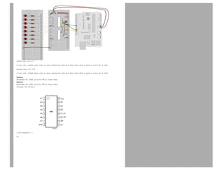
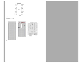
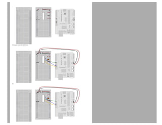
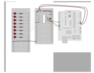
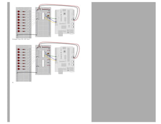
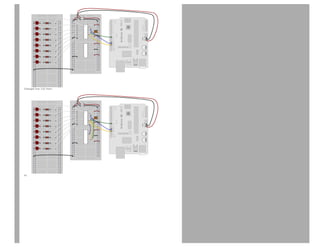
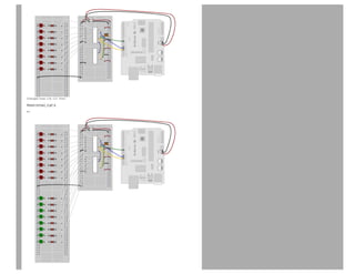
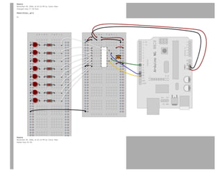
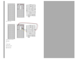
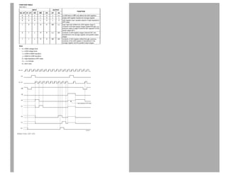
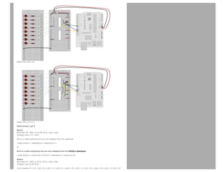
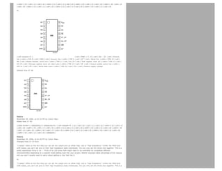
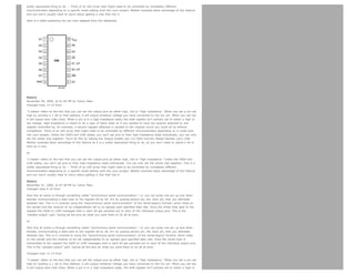
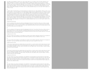
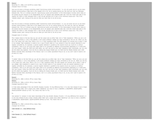
![November 01, 2006, at 06:45 PM by Carlyn Maw -
Changed lines 3-4 from:
Carlyn Maw, Tom Igoe
to:
Started by Carlyn Maw and Tom Igoe Nov, 06
Changed line 73 from:
Code Sample 2.1 – Dual Binary Counters
to:
Code Sample 2.1 – Dual Binary Counters
Added lines 75-97:
Code Sample 2.2 – 2 Byte One By One
Comparing this code to the similar code from Example 1 you see that a little bit more has had to change. The blinkAll()
function has been changed to the blinkAll_2Bytes() function to reflect the fact that now there are 16 LEDs to control. Also, in
version 1 the pulsings of the latchPin were situated inside the subfunctions lightShiftPinA and lightShiftPinB(). Here they need
to be moved back into the main loop to accommodate needing to run each subfunction twice in a row, once for the green
LEDs and once for the red ones.
Code Sample 2.3 - Dual Defined Arrays 2.3 also takes advantage of the new blinkAll_2bytes() function. Its big difference
from 1.3 is only that instead of just a single variable called “data” and a single array called “dataArray” you have to have a
dataRED, a dataGREEN, dataArrayRED, dataArrayGREEN defined up front. This means that later on line
data = dataArray[j];
becomes
dataRED = dataArrayRED[j];
dataGREEN = dataArrayGREEN[j];
and
shiftOut(dataPin, clockPin, data);
becomes
shiftOut(dataPin, clockPin, dataGREEN);
shiftOut(dataPin, clockPin, dataRED);
Restore
November 01, 2006, at 06:41 PM by Carlyn Maw -
Added lines 53-74:
Example 2
The Circuit
1. Add a second shift register.
Starting from the previous example, you should put a second shift register on the board. It should have the same leads to
power and ground.
2. Connect the 2 registers.
Two of these connections simply extend the same clock and latch signal from the Arduino to the second shift register (yellow
and green wires). The blue wire is going from the serial out pin (pin 9) of the first shift register to the serial data input (pin
14) of the second register.
3. Add a second set of LEDs.
In this case I added green ones so when reading the code it is clear which byte is going to which set of LEDs
The Code
Here again are three code samples. If you are curious, you might want to try the samples from the first example with this
circuit set up just to see what happens.
Code Sample 2.1 – Dual Binary Counters There is only one extra line of code compared to the first code sample from
Example 1. It sends out a second byte. This forces the first shift register, the one directly attached to the Arduino, to pass](https://image.slidesharecdn.com/arduino-learning-111105084504-phpapp01/85/Arduino-learning-554-320.jpg)
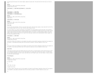

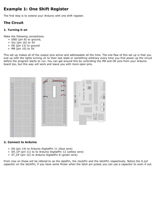
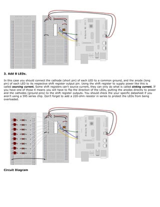
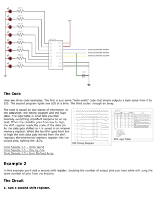

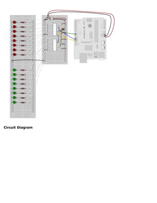
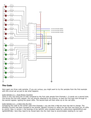
![subfunction twice in a row, once for the green LEDs and once for the red ones.
Code Sample 2.3 - Dual Defined Arrays
Like sample 2.2, sample 2.3 also takes advantage of the new blinkAll_2bytes() function. 2.3's big difference from
sample 1.3 is only that instead of just a single variable called “data” and a single array called “dataArray” you have
to have a dataRED, a dataGREEN, dataArrayRED, dataArrayGREEN defined up front. This means that line
data = dataArray[j];
becomes
dataRED = dataArrayRED[j];
dataGREEN = dataArrayGREEN[j];
and
shiftOut(dataPin, clockPin, data);
becomes
shiftOut(dataPin, clockPin, dataGREEN);
shiftOut(dataPin, clockPin, dataRED);
(Printable View of http://www.arduino.cc/en/Tutorial/ShiftOut)](https://image.slidesharecdn.com/arduino-learning-111105084504-phpapp01/85/Arduino-learning-567-320.jpg)

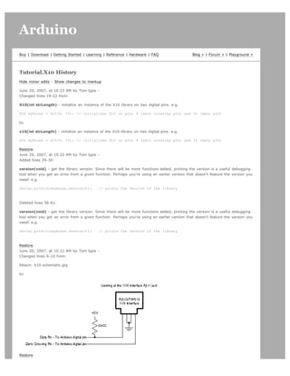
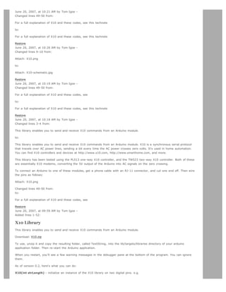
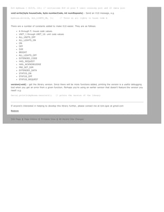

![Arduino search
Buy | Download | Getting Started | Learning | Reference | Hardware | FAQ Blog » | Forum » | Playground »
Tutorial.EEPROMClear History
Hide minor edits - Show changes to markup
May 21, 2008, at 09:32 PM by David A. Mellis -
Changed lines 29-31 from:
Example: EEPROM Read
Example: EEPROM Write
Reference: EEPROM library
to:
EEPROM Read example
EEPROM Write example
EEPROM library reference
Restore
May 21, 2008, at 09:32 PM by David A. Mellis -
Changed lines 25-31 from:
@]
to:
@]
See also
Example: EEPROM Read
Example: EEPROM Write
Reference: EEPROM library
Restore
May 21, 2008, at 09:27 PM by David A. Mellis -
Added lines 1-25:
Examples EEPROM Library
EEPROM Clear
Sets all of the bytes of the EEPROM to 0.
Code
#include EEPROM.h
void setup()
{
// write a 0 to all 512 bytes of the EEPROM
for (int i = 0; i 512; i++)
EEPROM.write(i, 0);
// turn the LED on when we're done
digitalWrite(13, HIGH);
}
void loop()
{](https://image.slidesharecdn.com/arduino-learning-111105084504-phpapp01/85/Arduino-learning-575-320.jpg)


![Arduino search
Buy | Download | Getting Started | Learning | Reference | Hardware | FAQ Blog » | Forum » | Playground »
Tutorial.EEPROMRead History
Hide minor edits - Show changes to markup
May 21, 2008, at 09:33 PM by David A. Mellis -
Changed lines 41-47 from:
@]
to:
@]
See also
EEPROM Clear example
EEPROM Write example
EEPROM library reference
Restore
May 21, 2008, at 09:28 PM by David A. Mellis -
Added lines 1-41:
Examples EEPROM Library
EEPROM Read
Reads the value of each byte of the EEPROM and prints it to the computer.
Code
#include EEPROM.h
// start reading from the first byte (address 0) of the EEPROM
int address = 0;
byte value;
void setup()
{
Serial.begin(9600);
}
void loop()
{
// read a byte from the current address of the EEPROM
value = EEPROM.read(address);
Serial.print(address);
Serial.print(t);
Serial.print(value, DEC);
Serial.println();
// advance to the next address of the EEPROM
address = address + 1;
// there are only 512 bytes of EEPROM, from 0 to 511, so if we're
// on address 512, wrap around to address 0
if (address == 512)](https://image.slidesharecdn.com/arduino-learning-111105084504-phpapp01/85/Arduino-learning-579-320.jpg)


![Arduino search
Buy | Download | Getting Started | Learning | Reference | Hardware | FAQ Blog » | Forum » | Playground »
Tutorial.EEPROMWrite History
Hide minor edits - Show changes to markup
May 21, 2008, at 09:33 PM by David A. Mellis -
Changed lines 40-46 from:
@]
to:
@]
See also
EEPROM Clear example
EEPROM Read example
EEPROM library reference
Restore
May 21, 2008, at 09:30 PM by David A. Mellis -
Added lines 1-40:
Examples EEPROM Library
EEPROM Write
Stores values read from analog input 0 into the EEPROM. These values will stay in the EEPROM when the board is turned off
and may be retrieved later by another sketch.
Code
#include EEPROM.h
// the current address in the EEPROM (i.e. which byte
// we're going to write to next)
int addr = 0;
void setup()
{
}
void loop()
{
// need to divide by 4 because analog inputs range from
// 0 to 1023 and each byte of the EEPROM can only hold a
// value from 0 to 255.
int val = analogRead(0) / 4;
// write the value to the appropriate byte of the EEPROM.
// these values will remain there when the board is
// turned off.
EEPROM.write(addr, val);
// advance to the next address. there are 512 bytes in
// the EEPROM, so go back to 0 when we hit 512.
addr = addr + 1;
if (addr == 512)](https://image.slidesharecdn.com/arduino-learning-111105084504-phpapp01/85/Arduino-learning-583-320.jpg)


![Arduino search
Buy | Download | Getting Started | Learning | Reference | Hardware | FAQ Blog » | Forum » | Playground »
Tutorial.MotorKnob History
Hide minor edits - Show changes to markup
May 21, 2008, at 09:40 PM by David A. Mellis -
Changed lines 45-46 from:
See Also
to:
See also
Restore
May 21, 2008, at 09:40 PM by David A. Mellis -
Changed lines 43-47 from:
@]
to:
@]
See Also
Stepper library reference
Restore
May 21, 2008, at 09:37 PM by David A. Mellis -
Changed lines 7-8 from:
A stepper motor follows the turns of a potentiometer (or other sensor) on analog input 0. The unipolar? or bipolar? stepper is
controlled with pins 8, 9, 10, and 11, using one of the circuits on the linked pages.
to:
A stepper motor follows the turns of a potentiometer (or other sensor) on analog input 0. The unipolar or bipolar stepper is
controlled with pins 8, 9, 10, and 11, using one of the circuits on the linked pages.
Restore
May 21, 2008, at 09:36 PM by David A. Mellis -
Added lines 1-43:
Examples Stepper Library
Motor Knob
Description
A stepper motor follows the turns of a potentiometer (or other sensor) on analog input 0. The unipolar? or bipolar? stepper is
controlled with pins 8, 9, 10, and 11, using one of the circuits on the linked pages.
Code
#include Stepper.h
// change this to the number of steps on your motor
#define STEPS 100](https://image.slidesharecdn.com/arduino-learning-111105084504-phpapp01/85/Arduino-learning-587-320.jpg)
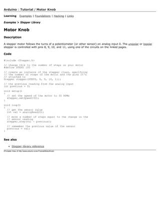

![PWM all of the digital pins in a sinewave pattern
Restore
May 10, 2007, at 07:07 PM by Paul Badger -
Changed lines 36-37 from:
http://www.arduino.cc/cgi-bin/yabb2/YaBB.pl?num=1171076259 |Use a couple of Arduino pins as a capacitive
sensor]]
to:
Use two Arduino pins as a capacitive sensor
Restore
May 10, 2007, at 07:05 PM by Paul Badger -
Changed lines 36-37 from:
http://www.arduino.cc/cgi-bin/yabb2/YaBB.pl?num=1171076259 Use a couple of Arduino pins as a capacitive sensor
to:
http://www.arduino.cc/cgi-bin/yabb2/YaBB.pl?num=1171076259 |Use a couple of Arduino pins as a capacitive
sensor]]
Restore
May 10, 2007, at 07:04 PM by Paul Badger -
Changed lines 36-37 from:
to:
http://www.arduino.cc/cgi-bin/yabb2/YaBB.pl?num=1171076259 Use a couple of Arduino pins as a capacitive sensor
Restore
May 10, 2007, at 06:59 PM by Paul Badger -
Added line 39:
More sound ideas
Restore
April 24, 2007, at 03:40 PM by Clay Shirky -
Changed lines 13-14 from:
Dimming 3 LEDs with Pulse-Width Modulation (PWM)
to:
Simple Dimming 3 LEDs with Pulse-Width Modulation (PWM)
More complex dimming/color crossfader
Restore
February 08, 2007, at 12:02 PM by Carlyn Maw -
Changed lines 52-53 from:
to:
Multiple digital inputs with a CD4021 Shift Register
Restore
February 06, 2007, at 02:52 PM by Carlyn Maw -
Changed lines 52-54 from:
Multiple digital ins with a CD4021 Shift Register
to:
Restore
February 06, 2007, at 02:51 PM by Carlyn Maw -
Changed lines 52-53 from:
to:
Multiple digital ins with a CD4021 Shift Register
Restore
January 30, 2007, at 03:37 PM by David A. Mellis -
Deleted line 46:](https://image.slidesharecdn.com/arduino-learning-111105084504-phpapp01/85/Arduino-learning-600-320.jpg)
![Arduino search
Buy | Download | Getting Started | Learning | Reference | Hardware | FAQ Blog » | Forum » | Playground »
Tutorial.HomePage History
Hide minor edits - Show changes to output
July 02, 2008, at 03:11 PM by David A. Mellis -
Changed lines 2-3 from:
!!Arduino Examples
to:
!!Examples
Restore
July 02, 2008, at 03:11 PM by David A. Mellis -
Changed lines 4-5 from:
''See the '''[[Tutorial/Foundations | foundations page]]''' for in-depth description of core concepts of the Arduino hardware and
software, and the '''[[Tutorial/Links | links page]]''' for other documentation.''
to:
''See the '''[[Tutorial/Foundations | foundations page]]''' for in-depth description of core concepts of the Arduino hardware and
software; the '''[[Hacking/HomePage | hacking page]]''' for information on extending and modifying the Arduino hardware and
software; and the '''[[Tutorial/Links | links page]]''' for other documentation.''
Restore
July 02, 2008, at 02:07 PM by David A. Mellis -
Added line 63:
* [[ Tutorial/ADXL3xx | Read an ADXL3xx accelerometer]]
Restore
May 21, 2008, at 09:44 PM by David A. Mellis -
Deleted lines 42-45:
!!!! Matrix Library
* [[HelloMatrix | Hello Matrix]]: blinks a smiley face on the LED matrix.
Restore
May 21, 2008, at 09:43 PM by David A. Mellis -
Added lines 43-46:
!!!! Matrix Library
* [[HelloMatrix | Hello Matrix]]: blinks a smiley face on the LED matrix.
Restore
May 21, 2008, at 09:36 PM by David A. Mellis -
Added lines 43-46:
!!!! Stepper Library
* [[MotorKnob | Motor Knob]]: control a stepper motor with a potentiometer.
Restore
May 21, 2008, at 09:25 PM by David A. Mellis - adding EEPROM examples.
Added lines 37-42:
!!!! EEPROM Library
* [[EEPROMClear | EEPROM Clear]]: clear the bytes in the EEPROM.
* [[EEPROMRead | EEPROM Read]]: read the EEPROM and send its values to the computer.
* [[EEPROMWrite | EEPROM Write]]: stores values from an analog input to the EEPROM.
Restore
May 21, 2008, at 09:22 PM by David A. Mellis -
Changed line 15 from:
* [[BlinkWithoutDelay | BlinkWithoutDelay]]: blinking an LED without using the delay() function.
to:
* [[BlinkWithoutDelay | Blink Without Delay]]: blinking an LED without using the delay() function.](https://image.slidesharecdn.com/arduino-learning-111105084504-phpapp01/85/Arduino-learning-607-320.jpg)
![Restore
April 29, 2008, at 06:55 PM by David A. Mellis - moving the resources to the links page.
Changed lines 2-5 from:
!!Arduino Tutorials
Here you will find a growing number of examples and tutorials for accomplishing specific tasks or interfacing to other
hardware and software with Arduino. For instructions on getting the board and environment up and running, see the Arduino
[[Guide/HomePage | Getting Started]].
to:
!!Arduino Examples
''See the '''[[Tutorial/Foundations | foundations page]]''' for in-depth description of core concepts of the Arduino hardware and
software, and the '''[[Tutorial/Links | links page]]''' for other documentation.''
Added line 15:
* [[BlinkWithoutDelay | BlinkWithoutDelay]]: blinking an LED without using the delay() function.
Changed lines 37-42 from:
!!!Timing Millis
* [[ Tutorial/BlinkWithoutDelay | Blinking an LED without using the delay() function]]
* [[ Tutorial/stopwatch | Stopwatch ]]
(:if false:)
* [[TimeSinceStart]]:
(:ifend:)
to:
(:cell width=50%:)
Changed lines 41-42 from:
These are more complex examples for using particular electronic components or accomplishing specific tasks. The code is
included in the tutorial.
to:
These are more complex examples for using particular electronic components or accomplishing specific tasks. The code is
included on the page.
Deleted lines 43-44:
Added lines 49-51:
!!!Timing Millis
* [[ Tutorial/stopwatch | Stopwatch ]]
Deleted lines 75-125:
(:cell width=50%:)
!!!Foundations
See the [[Foundations| foundations page]] for explanations of the concepts involved in the Arduino hardware and software.
!!!Tutorials
Tutorials created by the Arduino community. Hosted on the publicly-editable [[http://www.arduino.cc/playground/ |
playground wiki]].
[[http://www.arduino.cc/playground/Main/ArduinoCoreHardware | Board Setup and Configuration]]: Information about the
components and usage of Arduino hardware.
[[http://www.arduino.cc/playground/Main/InterfacingWithHardware | Interfacing With Hardware]]: Code, circuits, and
instructions for using various electronic components with an Arduino board.
* [[http://www.arduino.cc/playground/Main/InterfacingWithHardware#Output | Output]]
* [[http://www.arduino.cc/playground/Main/InterfacingWithHardware#Input | Input]]
* [[http://www.arduino.cc/playground/Main/InterfacingWithHardware#Interaction | Interaction]]
* [[http://www.arduino.cc/playground/Main/InterfacingWithHardware#Storage | Storage]]
* [[http://www.arduino.cc/playground/Main/InterfacingWithHardware#Communication | Communication]]
[[http://www.arduino.cc/playground/Main/InterfacingWithSoftware | Interfacing with Software]]: how to get an Arduino board
talking to software running on the computer (e.g. Processing, PD, Flash, Max/MSP).
[[http://www.arduino.cc/playground/Main/GeneralCodeLibrary | Code Library and Tutorials]]: Arduino functions for performing
specific tasks and other programming tutorials.
[[http://www.arduino.cc/playground/Main/ElectroInfoResources | Electronics Techniques]]: tutorials on soldering and other
electronics resources.](https://image.slidesharecdn.com/arduino-learning-111105084504-phpapp01/85/Arduino-learning-608-320.jpg)
![!!!Manuals, Curricula, and Other Resources
[[http://www.tinker.it/en/uploads/v3_arduino_small.pdf | Arduino Booklet (pdf)]]: an illustrated guide to the philosophy and
practice of Arduino.
[[http://www.ladyada.net/learn/arduino/index.html | Learn electronics using Arduino]]: an introduction to programming, input
/ output, communication, etc. using Arduino. By [[http://www.ladyada.net/ | ladyada]].
* [[http://www.ladyada.net/learn/arduino/lesson0.html | Lesson 0]]: Pre-flight check...Is your Arduino and computer ready?
* [[http://www.ladyada.net/learn/arduino/lesson1.html | Lesson 1]]: The quot;Hello World!quot; of electronics, a simple
blinking light
* [[http://www.ladyada.net/learn/arduino/lesson2.html | Lesson 2]]: Sketches, variables, procedures and hacking code
* [[http://www.ladyada.net/learn/arduino/lesson3.html | Lesson 3]]: Breadboards, resistors and LEDs, schematics, and basic
RGB color-mixing
* [[http://www.ladyada.net/learn/arduino/lesson4.html | Lesson 4]]: The serial library and binary data - getting chatty with
Arduino and crunching numbers
* [[http://www.ladyada.net/learn/arduino/lesson5.html | Lesson 5]]: Buttons amp; switches, digital inputs, pull-up and pull-
down resistors, if/if-else statements, debouncing and your first contract product design.
[[ http://itp.nyu.edu/physcomp/Labs/Labs | Example labs from ITP]]
[[http://todbot.com/blog/spookyarduino/ | Spooky Arduino]]: Longer presentation-format documents introducing Arduino from
a Halloween hacking class taught by TodBot:
* [[http://todbot.com/blog/wp-content/uploads/2006/10/arduino_spooky_projects_class1.pdf | class 1 (getting started)]]
* [[http://todbot.com/blog/wp-content/uploads/2006/10/arduino_spooky_projects_class2.pdf | class 2 (input and sensors)]]
* [[http://todbot.com/blog/wp-content/uploads/2006/10/arduino_spooky_projects_class3.pdf | class 3 (communication, servos,
and pwm)]]
* [[http://todbot.com/blog/wp-content/uploads/2006/10/arduino_spooky_projects_class4.pdf | class 4 (piezo sound sensors,
arduino+processing, stand-alone operation)]]
[[http://todbot.com/blog/bionicarduino/ | Bionic Arduino]]: another Arduino class from TodBot, this one focusing on physical
sensing and making motion.
[[http://www.tigoe.net/pcomp/code/archives/avr/arduino/index.shtml | Examples from Tom Igoe]]
[[http://www.grayfuse.com/blog/?p=15 | Examples from Jeff Gray]]
Restore
April 23, 2008, at 10:29 PM by David A. Mellis -
Changed line 6 from:
(:table width=90% border=0 cellpadding=5 cellspacing=0:)
to:
(:table width=100% border=0 cellpadding=5 cellspacing=0:)
Restore
April 22, 2008, at 05:59 PM by Paul Badger -
Changed line 39 from:
to:
(:if false:)
Changed line 41 from:
to:
(:ifend:)
Restore
April 22, 2008, at 05:56 PM by Paul Badger -
Added lines 40-41:
* [[TimeSinceStart]]:
Restore
April 18, 2008, at 07:22 AM by Paul Badger -
Added lines 36-39:
!!!Timing Millis
* [[ Tutorial/BlinkWithoutDelay | Blinking an LED without using the delay() function]]
* [[ Tutorial/stopwatch | Stopwatch ]]
Changed line 46 from:
* [[ Tutorial/BlinkWithoutDelay | Blinking an LED without using the delay() function]]
to:](https://image.slidesharecdn.com/arduino-learning-111105084504-phpapp01/85/Arduino-learning-609-320.jpg)
![Restore
April 08, 2008, at 08:23 PM by David A. Mellis -
Changed line 43 from:
* * [[TwoSwitchesOnePin]]: Read two switches with one I/O pin
to:
* [[TwoSwitchesOnePin]]: Read two switches with one I/O pin
Restore
April 08, 2008, at 08:22 PM by David A. Mellis - moving TwoSwitchesOnePin to other examples since it's not (yet) in the
distribution.
Changed lines 18-19 from:
* [[TwoSwitchesOnePin]]: Read two switches with one I/O pin
to:
Added line 43:
* * [[TwoSwitchesOnePin]]: Read two switches with one I/O pin
Restore
April 08, 2008, at 07:41 PM by Paul Badger -
Changed lines 18-19 from:
to:
* [[TwoSwitchesOnePin]]: Read two switches with one I/O pin
Restore
March 09, 2008, at 07:20 PM by David A. Mellis -
Changed lines 73-78 from:
* [[Foundations| Foundations has moved here]]
* [[Bootloader]]: A small program pre-loaded on the Arduino board to allow uploading sketches.
to:
See the [[Foundations| foundations page]] for explanations of the concepts involved in the Arduino hardware and software.
Restore
March 07, 2008, at 09:26 PM by Paul Badger -
Changed lines 73-75 from:
to:
* [[Foundations| Foundations has moved here]]
Restore
March 07, 2008, at 09:24 PM by Paul Badger -
Changed lines 74-107 from:
* [[Memory]]: The various types of memory available on the Arduino board.
* [[Digital Pins]]: How the pins work and what it means for them to be configured as inputs or outputs.
* [[Analog Input Pins]]: Details about the analog-to-digital conversion and other uses of the pins.
* [[Foundations]]
(:if false:)
* [[PWM | PWM (Pulse-Width Modulation)]]: The method used by analogWrite() to simulate an analog output with digital
pins.
* [[Communication]]: An overview of the various ways in which an Arduino board can communicate with other devices
(serial, I2C, SPI, Midi, etc.)
* [[Serial | Serial Communication]]: How to send serial data from an Arduino board to a computer or other device (including
via the USB connection).
* [[Interrupts]]: Code that interrupts other code under certain conditions.
* [[Numbers]]: The various types of numbers available and how to use them.](https://image.slidesharecdn.com/arduino-learning-111105084504-phpapp01/85/Arduino-learning-610-320.jpg)
![* [[Variables]]: How to define and use variables.
* [[Arrays]]: How to store multiple values of the same type.
* [[Pointers]]:
* [[Functions]]: How to write and call functions.
* [[Optimization]]: What to do when your program runs too slowly.
* [[Debugging]]: Figuring out what's wrong with your hardware or software and how to fix it.
(:ifend:)
to:
Restore
March 07, 2008, at 09:09 PM by Paul Badger -
Added lines 80-81:
* [[Foundations]]
Restore
February 15, 2008, at 06:00 PM by David A. Mellis -
Changed lines 72-73 from:
!!!Tutorials
to:
!!!Foundations
Changed lines 108-109 from:
!!!More Tutorials
to:
!!!Tutorials
Restore
February 13, 2008, at 10:42 PM by Paul Badger -
Changed lines 4-5 from:
Here you will find a growing number of examples and tutorials for accomplishing specific tasks or interfacing to other
hardware and software with Arduino. For instructions on getting the board and environment up and running, see the Arduino
[[Guide/HomePage | guide]].
to:
Here you will find a growing number of examples and tutorials for accomplishing specific tasks or interfacing to other
hardware and software with Arduino. For instructions on getting the board and environment up and running, see the Arduino
[[Guide/HomePage | Getting Started]].
Restore
February 13, 2008, at 10:06 PM by David A. Mellis -
Restore
February 13, 2008, at 09:58 PM by David A. Mellis -
Added lines 100-103:
* [[Optimization]]: What to do when your program runs too slowly.
* [[Debugging]]: Figuring out what's wrong with your hardware or software and how to fix it.
Restore
February 13, 2008, at 09:41 PM by David A. Mellis -
Added lines 90-99:
* [[Numbers]]: The various types of numbers available and how to use them.
* [[Variables]]: How to define and use variables.
* [[Arrays]]: How to store multiple values of the same type.
* [[Pointers]]:
* [[Functions]]: How to write and call functions.
Restore
February 13, 2008, at 09:38 PM by David A. Mellis -
Changed lines 86-87 from:
* [[Serial | Serial Communication]]: How to send serial data from an Arduino board to a computer or other device.
to:](https://image.slidesharecdn.com/arduino-learning-111105084504-phpapp01/85/Arduino-learning-611-320.jpg)
![* [[Serial | Serial Communication]]: How to send serial data from an Arduino board to a computer or other device (including
via the USB connection).
* [[Interrupts]]: Code that interrupts other code under certain conditions.
Restore
February 13, 2008, at 09:36 PM by David A. Mellis -
Added lines 80-81:
(:if false:)
Added lines 84-89:
* [[Communication]]: An overview of the various ways in which an Arduino board can communicate with other devices
(serial, I2C, SPI, Midi, etc.)
* [[Serial | Serial Communication]]: How to send serial data from an Arduino board to a computer or other device.
(:ifend:)
Restore
February 13, 2008, at 09:31 PM by David A. Mellis -
Changed lines 80-81 from:
* [[PWM]] (Pulse-Width Modulation): The method used by analogWrite() to simulate an analog output with digital pins.
to:
* [[PWM | PWM (Pulse-Width Modulation)]]: The method used by analogWrite() to simulate an analog output with digital
pins.
Restore
February 13, 2008, at 09:30 PM by David A. Mellis -
Added lines 80-81:
* [[PWM]] (Pulse-Width Modulation): The method used by analogWrite() to simulate an analog output with digital pins.
Restore
February 13, 2008, at 09:22 PM by David A. Mellis -
Added lines 80-81:
* [[Bootloader]]: A small program pre-loaded on the Arduino board to allow uploading sketches.
Restore
February 13, 2008, at 09:12 PM by David A. Mellis -
Added lines 74-81:
* [[Memory]]: The various types of memory available on the Arduino board.
* [[Digital Pins]]: How the pins work and what it means for them to be configured as inputs or outputs.
* [[Analog Input Pins]]: Details about the analog-to-digital conversion and other uses of the pins.
!!!More Tutorials
Restore
January 11, 2008, at 11:31 AM by David A. Mellis - linking to board setup and configuration on the playground.
Added lines 76-77:
[[http://www.arduino.cc/playground/Main/ArduinoCoreHardware | Board Setup and Configuration]]: Information about the
components and usage of Arduino hardware.
Restore
December 19, 2007, at 11:54 PM by David A. Mellis - adding links to other pages: the tutorial parts of the playground,
ladyada's tutorials, todbot, etc.
Changed lines 36-42 from:
(:cell width=50%:)
!!!Tutorials
These are more complex tutorials for using particular electronic components or accomplishing specific tasks. The code is
included in the tutorial.
to:
!!!Other Examples
These are more complex examples for using particular electronic components or accomplishing specific tasks. The code is
included in the tutorial.
Changed lines 71-78 from:
!!!!Other Arduino Tutorials
* [[http://www.arduino.cc/playground/Learning/Tutorials | Tutorials from the Arduino playground]]](https://image.slidesharecdn.com/arduino-learning-111105084504-phpapp01/85/Arduino-learning-612-320.jpg)
![* [[ http://itp.nyu.edu/physcomp/Labs/Labs | Example labs from ITP]]
* [[http://todbot.com/blog/category/arduino/ | Spooky Arduino and more from Todbot]]
* [[http://www.tigoe.net/pcomp/code/archives/avr/arduino/index.shtml | Examples from Tom Igoe]]
* [[http://www.grayfuse.com/blog/?p=15 | Examples from Jeff Gray]]
to:
(:cell width=50%:)
!!!Tutorials
Tutorials created by the Arduino community. Hosted on the publicly-editable [[http://www.arduino.cc/playground/ |
playground wiki]].
[[http://www.arduino.cc/playground/Main/InterfacingWithHardware | Interfacing With Hardware]]: Code, circuits, and
instructions for using various electronic components with an Arduino board.
* [[http://www.arduino.cc/playground/Main/InterfacingWithHardware#Output | Output]]
* [[http://www.arduino.cc/playground/Main/InterfacingWithHardware#Input | Input]]
* [[http://www.arduino.cc/playground/Main/InterfacingWithHardware#Interaction | Interaction]]
* [[http://www.arduino.cc/playground/Main/InterfacingWithHardware#Storage | Storage]]
* [[http://www.arduino.cc/playground/Main/InterfacingWithHardware#Communication | Communication]]
[[http://www.arduino.cc/playground/Main/InterfacingWithSoftware | Interfacing with Software]]: how to get an Arduino board
talking to software running on the computer (e.g. Processing, PD, Flash, Max/MSP).
[[http://www.arduino.cc/playground/Main/GeneralCodeLibrary | Code Library and Tutorials]]: Arduino functions for performing
specific tasks and other programming tutorials.
[[http://www.arduino.cc/playground/Main/ElectroInfoResources | Electronics Techniques]]: tutorials on soldering and other
electronics resources.
!!!Manuals, Curricula, and Other Resources
[[http://www.tinker.it/en/uploads/v3_arduino_small.pdf | Arduino Booklet (pdf)]]: an illustrated guide to the philosophy and
practice of Arduino.
[[http://www.ladyada.net/learn/arduino/index.html | Learn electronics using Arduino]]: an introduction to programming, input
/ output, communication, etc. using Arduino. By [[http://www.ladyada.net/ | ladyada]].
* [[http://www.ladyada.net/learn/arduino/lesson0.html | Lesson 0]]: Pre-flight check...Is your Arduino and computer ready?
* [[http://www.ladyada.net/learn/arduino/lesson1.html | Lesson 1]]: The quot;Hello World!quot; of electronics, a simple
blinking light
* [[http://www.ladyada.net/learn/arduino/lesson2.html | Lesson 2]]: Sketches, variables, procedures and hacking code
* [[http://www.ladyada.net/learn/arduino/lesson3.html | Lesson 3]]: Breadboards, resistors and LEDs, schematics, and basic
RGB color-mixing
* [[http://www.ladyada.net/learn/arduino/lesson4.html | Lesson 4]]: The serial library and binary data - getting chatty with
Arduino and crunching numbers
* [[http://www.ladyada.net/learn/arduino/lesson5.html | Lesson 5]]: Buttons amp; switches, digital inputs, pull-up and pull-
down resistors, if/if-else statements, debouncing and your first contract product design.
[[ http://itp.nyu.edu/physcomp/Labs/Labs | Example labs from ITP]]
[[http://todbot.com/blog/spookyarduino/ | Spooky Arduino]]: Longer presentation-format documents introducing Arduino from
a Halloween hacking class taught by TodBot:
* [[http://todbot.com/blog/wp-content/uploads/2006/10/arduino_spooky_projects_class1.pdf | class 1 (getting started)]]
* [[http://todbot.com/blog/wp-content/uploads/2006/10/arduino_spooky_projects_class2.pdf | class 2 (input and sensors)]]
* [[http://todbot.com/blog/wp-content/uploads/2006/10/arduino_spooky_projects_class3.pdf | class 3 (communication, servos,
and pwm)]]
* [[http://todbot.com/blog/wp-content/uploads/2006/10/arduino_spooky_projects_class4.pdf | class 4 (piezo sound sensors,
arduino+processing, stand-alone operation)]]
[[http://todbot.com/blog/bionicarduino/ | Bionic Arduino]]: another Arduino class from TodBot, this one focusing on physical
sensing and making motion.
[[http://www.tigoe.net/pcomp/code/archives/avr/arduino/index.shtml | Examples from Tom Igoe]]
[[http://www.grayfuse.com/blog/?p=15 | Examples from Jeff Gray]]](https://image.slidesharecdn.com/arduino-learning-111105084504-phpapp01/85/Arduino-learning-613-320.jpg)
![Restore
December 13, 2007, at 11:08 PM by David A. Mellis - adding debounce example.
Added line 16:
* [[Debounce]]: read a pushbutton, filtering noise.
Restore
August 28, 2007, at 11:15 PM by Tom Igoe -
Changed lines 71-72 from:
to:
* [[Tutorial/X10 | X10 output]] control devices over AC powerlines using X10
Restore
June 15, 2007, at 05:04 PM by David A. Mellis - adding link to Processing (for the communication examples)
Added lines 27-28:
''These examples include code that allows the Arduino to talk to Processing sketches running on the computer. For more
information or to download Processing, see [[http://processing.org/ | processing.org]].''
Restore
June 12, 2007, at 08:57 AM by David A. Mellis - removing link to obsolete joystick example.
Deleted line 43:
* [[ Tutorial/JoyStick | Interfacing a Joystick]]
Restore
June 11, 2007, at 11:14 PM by David A. Mellis -
Changed lines 10-11 from:
Simple programs that demonstrate the use of the Arduino board. These are included with the Arduino environment; to open
them, click the Open button on the toolbar and look in the '''examples''' folder. (If you're looking for an older example, check
the [[HomePage-0007 | Arduino 0007 tutorials page]].
to:
Simple programs that demonstrate the use of the Arduino board. These are included with the Arduino environment; to open
them, click the Open button on the toolbar and look in the '''examples''' folder. (If you're looking for an older example, check
the [[HomePage-0007 | Arduino 0007 tutorials page]].)
Restore
June 11, 2007, at 11:13 PM by David A. Mellis -
Changed lines 10-11 from:
Simple programs that demonstrate the use of the Arduino board. These are included with the Arduino environment; to open
them, click the Open button on the toolbar and look in the '''examples''' folder.
to:
Simple programs that demonstrate the use of the Arduino board. These are included with the Arduino environment; to open
them, click the Open button on the toolbar and look in the '''examples''' folder. (If you're looking for an older example, check
the [[HomePage-0007 | Arduino 0007 tutorials page]].
Restore
June 11, 2007, at 11:10 PM by David A. Mellis - updating to 0008 examples
Changed lines 10-11 from:
!!!! Digital Output
* [[ Tutorial/Blinking LED | Blinking LED]]
to:
Simple programs that demonstrate the use of the Arduino board. These are included with the Arduino environment; to open
them, click the Open button on the toolbar and look in the '''examples''' folder.
!!!! Digital I/O
* [[Blink]]: turn an LED on and off.
* [[Button]]: use a pushbutton to control an LED.
* [[Loop]]: controlling multiple LEDs with a loop and an array.
!!!! Analog I/O
* [[Analog Input]]: use a potentiometer to control the blinking of an LED.
* [[Fading]]: uses an analog output (PWM pin) to fade an LED.
* [[Knock]]: detect knocks with a piezo element.
* [[Smoothing]]: smooth multiple readings of an analog input.
!!!! Communication
* [[ASCII Table]]: demonstrates Arduino's advanced serial output functions.
* [[Dimmer]]: move the mouse to change the brightness of an LED.](https://image.slidesharecdn.com/arduino-learning-111105084504-phpapp01/85/Arduino-learning-614-320.jpg)
![* [[Graph]]: sending data to the computer and graphing it in Processing.
* [[Physical Pixel]]: turning on and off an LED by sending data from Processing.
* [[Virtual Color Mixer]]: sending multiple variables from Arduino to the computer and reading them in Processing.
(:cell width=50%:)
!!!Tutorials
These are more complex tutorials for using particular electronic components or accomplishing specific tasks. The code is
included in the tutorial.
!!!!Miscellaneous
Deleted lines 42-51:
* [[ Tutorial/Dimming LEDs | Simple Dimming 3 LEDs with Pulse-Width Modulation (PWM) ]]
* [[ Tutorial/Color Crossfader | More complex dimming/color crossfader ]]
* [[ Tutorial/Knight Rider|Knight Rider example]]
* [[ Tutorial/ShootingStar | Shooting star]]
* [[ http://www.arduino.cc/playground/Main/PWMallPins | PWM all of the digital pins in a sinewave pattern]]
!!!! Digital Input
* [[http://itp.nyu.edu/physcomp/Labs/DigitalInOut | Digital Input and Output]] (from [[http://itp.nyu.edu/physcomp/Labs/Labs
| ITP physcomp labs]])
* [[ Tutorial/Pushbutton | Read a Pushbutton]]
* [[ Tutorial/Switch | Using a pushbutton as a switch]]
Deleted lines 43-45:
!!!! Analog Input
* [[ Tutorial/Potentiometer | Read a Potentiometer]]
Deleted lines 45-46:
* [[ Tutorial/Knock Sensor | Read a Piezo Sensor]]
* [[ Tutorial/LED cross-fades with potentiometer | 3 LED cross-fades with a potentiometer ]]
Changed lines 52-53 from:
*[[http://www.arduino.cc/cgi-bin/yabb2/YaBB.pl?num=1171076259 | Use two Arduino pins as a capacitive sensor]]
to:
Deleted line 54:
* [[http://www.arduino.cc/playground/Main/Freqout|More sound ideas]]
Added line 64:
* [[ Tutorial/DMX Master | Build your own DMX Master device]]
Changed lines 70-72 from:
*[[Tutorial/ShiftIn | Multiple digital inputs with a CD4021 Shift Register]]
!!!Other Arduino Examples
to:
!!!!Other Arduino Tutorials
* [[http://www.arduino.cc/playground/Learning/Tutorials | Tutorials from the Arduino playground]]
Added line 75:
* [[http://todbot.com/blog/category/arduino/ | Spooky Arduino and more from Todbot]]
Deleted lines 78-105:
(:cell width=50%:)
!!!Interfacing with Other Software
* [[http://itp.nyu.edu/physcomp/Labs/Serial | Introduction to Serial Communication]] (from
[[http://itp.nyu.edu/physcomp/Labs/Labs | ITP physcomp labs]])
* [[http://www.arduino.cc/playground/Interfacing/Flash | Arduino + Flash]]
* [[http://www.arduino.cc/playground/Interfacing/Processing | Arduino + Processing]]
* [[http://www.arduino.cc/playground/Interfacing/PD | Arduino + PD]]
* [[http://www.arduino.cc/playground/Interfacing/MaxMSP | Arduino + MaxMSP]]
* [[http://www.arduino.cc/playground/Interfacing/VVVV | Arduino + VVVV]]
* [[http://www.arduino.cc/playground/Interfacing/Director | Arduino + Director]]
* [[http://www.arduino.cc/playground/Interfacing/Ruby | Arduino + Ruby]]
* [[http://todbot.com/blog/2006/12/06/arduino-serial-c-code-to-talk-to-arduino/ | Arduino + C]]](https://image.slidesharecdn.com/arduino-learning-111105084504-phpapp01/85/Arduino-learning-615-320.jpg)
![!!!Tech Notes (from the [[http://www.arduino.cc/cgi-bin/yabb2/YaBB.pl | forums]] or [[http://www.arduino.cc/playground/ |
playground]])
* [[http://www.arduino.cc/cgi-bin/yabb2/YaBB.pl?num=1147888882 | Software serial]] (serial on pins besides 0 and 1)
* [[http://www.arduino.cc/cgi-bin/yabb2/YaBB.pl?num=1138310274 | L297 motor driver]]
* [[http://www.arduino.cc/cgi-bin/yabb2/YaBB.pl?num=1135701338 | Hex inverter]]
* [[http://www.arduino.cc/cgi-bin/yabb2/YaBB.pl?num=1138666403 | Analog multiplexer]]
* [[http://www.arduino.cc/cgi-bin/yabb2/YaBB.pl?num=1138892708 | Power supplies]]
* [[http://www.arduino.cc/cgi-bin/yabb2/YaBB.pl?num=1139161553 | The components on the Arduino board]]
* [[http://www.arduino.cc/playground/Learning/BuildProcess | Arduino build process]]
* [[http://www.arduino.cc/playground/Code/OSXISPMKII | AVRISP mkII on the Mac]]
* [[http://www.arduino.cc/playground/Code/EEPROM-Flash | Non-volatile memory (EEPROM)]]
* [[http://www.arduino.cc/playground/Learning/Tutorial01 | Bluetooth]]
* [[http://mrtof.danslchamp.org/AXIC | Zigbee]]
* [[http://www.arduino.cc/cgi-bin/yabb2/YaBB.pl?num=1146679536 | LED as light sensor]] (en Francais)
* [[http://www.arduino.cc/playground/Learning/Asuro | Arduino and the Asuro robot]]
* [[http://www.arduino.cc/playground/Learning/CommandLine | Using Arduino from the command line]]
Restore
May 11, 2007, at 06:06 AM by Paul Badger -
Changed lines 17-18 from:
to:
* [[ http://www.arduino.cc/playground/Main/PWMallPins | PWM all of the digital pins in a sinewave pattern]]
Restore
May 10, 2007, at 07:07 PM by Paul Badger -
Changed lines 36-37 from:
* [[http://www.arduino.cc/cgi-bin/yabb2/YaBB.pl?num=1171076259]] |Use a couple of Arduino pins as a capacitive sensor]]
to:
*[[http://www.arduino.cc/cgi-bin/yabb2/YaBB.pl?num=1171076259 | Use two Arduino pins as a capacitive sensor]]
Restore
May 10, 2007, at 07:05 PM by Paul Badger -
Changed lines 36-37 from:
* [[http://www.arduino.cc/cgi-bin/yabb2/YaBB.pl?num=1171076259]] Use a couple of Arduino pins as a capacitive sensor
to:
* [[http://www.arduino.cc/cgi-bin/yabb2/YaBB.pl?num=1171076259]] |Use a couple of Arduino pins as a capacitive sensor]]
Restore
May 10, 2007, at 07:04 PM by Paul Badger -
Changed lines 36-37 from:
to:
* [[http://www.arduino.cc/cgi-bin/yabb2/YaBB.pl?num=1171076259]] Use a couple of Arduino pins as a capacitive sensor
Restore
May 10, 2007, at 06:59 PM by Paul Badger -
Added line 39:
* [[http://www.arduino.cc/playground/Main/Freqout|More sound ideas]]
Restore
April 24, 2007, at 03:40 PM by Clay Shirky -
Changed lines 13-14 from:
* [[ Tutorial/Dimming LEDs | Dimming 3 LEDs with Pulse-Width Modulation (PWM) ]]
to:
* [[ Tutorial/Dimming LEDs | Simple Dimming 3 LEDs with Pulse-Width Modulation (PWM) ]]
* [[ Tutorial/Color Crossfader | More complex dimming/color crossfader ]]
Restore
February 08, 2007, at 12:02 PM by Carlyn Maw -
Changed lines 52-53 from:
to:
*[[Tutorial/ShiftIn | Multiple digital inputs with a CD4021 Shift Register]]
Restore
February 06, 2007, at 02:52 PM by Carlyn Maw -
Changed lines 52-54 from:
*[[Tutorial/ShiftIn | Multiple digital ins with a CD4021 Shift Register]]
to:
Restore
February 06, 2007, at 02:51 PM by Carlyn Maw -
Changed lines 52-53 from:](https://image.slidesharecdn.com/arduino-learning-111105084504-phpapp01/85/Arduino-learning-616-320.jpg)
![to:
*[[Tutorial/ShiftIn | Multiple digital ins with a CD4021 Shift Register]]
Restore
January 30, 2007, at 03:37 PM by David A. Mellis -
Deleted line 46:
* [[ Tutorial/DMX Master | Build your own DMX Master device]]
Restore
December 25, 2006, at 11:57 PM by David A. Mellis -
Added line 20:
* [[ Tutorial/Switch | Using a pushbutton as a switch]]
Restore
December 07, 2006, at 06:04 AM by David A. Mellis - adding link to todbot's C serial port code.
Changed lines 69-70 from:
to:
* [[http://todbot.com/blog/2006/12/06/arduino-serial-c-code-to-talk-to-arduino/ | Arduino + C]]
Restore
December 02, 2006, at 10:43 AM by David A. Mellis -
Added line 1:
(:title Tutorials:)
Restore
November 21, 2006, at 10:13 AM by David A. Mellis -
Added line 64:
* [[http://www.arduino.cc/playground/Interfacing/MaxMSP | Arduino + MaxMSP]]
Changed lines 67-68 from:
to:
* [[http://www.arduino.cc/playground/Interfacing/Ruby | Arduino + Ruby]]
Restore
November 18, 2006, at 02:42 AM by David A. Mellis -
Changed lines 20-21 from:
* [[ Tutorial/ControleLEDcircleWithJoystick | Controlling an LED circle with a joystick]]
to:
Added line 24:
* [[ Tutorial/ControleLEDcircleWithJoystick | Controlling an LED circle with a joystick]]
Restore
November 09, 2006, at 03:10 PM by Carlyn Maw -
Changed lines 50-51 from:
to:
*[[Tutorial/ShiftOut | Multiple digital outs with a 595 Shift Register]]
Restore
November 06, 2006, at 10:49 AM by David A. Mellis -
Changed lines 37-38 from:
* [[http://itp.nyu.edu/physcomp/Labs/MIDIOutput | MIDI Output]] (from [[http://itp.nyu.edu/physcomp/Labs/Labs | ITP
physcomp labs]])
to:
* [[http://itp.nyu.edu/physcomp/Labs/MIDIOutput | MIDI Output]] (from [[http://itp.nyu.edu/physcomp/Labs/Labs | ITP
physcomp labs]]) and [[http://todbot.com/blog/2006/10/29/spooky-arduino-projects-4-and-musical-arduino/ | from Spooky
Arduino]]
Restore
November 04, 2006, at 12:25 PM by David A. Mellis -
Deleted line 53:
Deleted line 54:
Restore
November 04, 2006, at 12:24 PM by David A. Mellis -
Added lines 51-58:
!!!Other Arduino Examples
* [[ http://itp.nyu.edu/physcomp/Labs/Labs | Example labs from ITP]]
* [[http://www.tigoe.net/pcomp/code/archives/avr/arduino/index.shtml | Examples from Tom Igoe]]](https://image.slidesharecdn.com/arduino-learning-111105084504-phpapp01/85/Arduino-learning-617-320.jpg)
![* [[http://www.grayfuse.com/blog/?p=15 | Examples from Jeff Gray]]
Deleted lines 83-89:
!!!Other Arduino Examples
* [[ http://itp.nyu.edu/physcomp/Labs/Labs | Example labs from ITP]]
* [[http://www.tigoe.net/pcomp/code/archives/avr/arduino/index.shtml | Examples from Tom Igoe]].
* [[http://www.grayfuse.com/blog/?p=15 | Examples from Jeff Gray]].
Restore
November 04, 2006, at 12:24 PM by David A. Mellis -
Changed lines 50-51 from:
!!!! [[ http://itp.nyu.edu/physcomp/Labs/Labs | Example labs from ITP]]
to:
Changed lines 77-78 from:
Also, see the [[http://www.tigoe.net/pcomp/code/archives/avr/arduino/index.shtml | examples from Tom Igoe]] and
[[http://www.grayfuse.com/blog/?p=15 | those from Jeff Gray]].
to:
* [[ http://itp.nyu.edu/physcomp/Labs/Labs | Example labs from ITP]]
* [[http://www.tigoe.net/pcomp/code/archives/avr/arduino/index.shtml | Examples from Tom Igoe]].
* [[http://www.grayfuse.com/blog/?p=15 | Examples from Jeff Gray]].
Restore
November 04, 2006, at 12:23 PM by David A. Mellis -
Changed line 77 from:
!!!Other Arduino Sites
to:
!!!Other Arduino Examples
Deleted lines 79-81:
!!!Do you need extra help?
Is there a sensor you would like to see characterized for Arduino, or is there something you would like to see published in
this site? Refer to the [[ http://www.arduino.cc/cgi-bin/yabb2/YaBB.pl | forum]] for further help.
Restore
November 04, 2006, at 10:38 AM by David A. Mellis -
Changed lines 3-4 from:
Here you will find a growing number of examples and tutorials for accomplishing specific tasks or interfacing to other
hardware and software with Arduino. For instructions on getting the board and environment up and running, see the Arduino
[[Guide/Homepage | guide]].
to:
Here you will find a growing number of examples and tutorials for accomplishing specific tasks or interfacing to other
hardware and software with Arduino. For instructions on getting the board and environment up and running, see the Arduino
[[Guide/HomePage | guide]].
Restore
November 04, 2006, at 10:37 AM by David A. Mellis - lots of content moved to the new guide.
Deleted lines 52-67:
!!!The Arduino board
This [[ Tutorial/ArduinoBoard | guide to the Arduino board]] explains the functions of the various parts of the board.
!!!The Arduino environment
This [[Main/Environment | guide to the Arduino IDE]] (integrated development environment) explains the functions of the
various buttons and menus.
The [[Main/libraries]] page explains how to use libraries in your sketches and how to make your own.
!!!Video Lectures by Tom Igoe
[[http://www.sbk.flr4.org/arduino/index.html | Watch Tom]] introduce Arduino. Thanks to Pollie Barden for the great videos.
!!!Course Guides
[[http://todbot.com/blog | todbot]] has some very detailed, illustrated tutorials from his
[[http://todbot.com/blog/spookyarduino/ | Spooky Projects]] course: [[http://todbot.com/blog/wp-
content/uploads/2006/10/arduino_spooky_projects_class1.pdf | class 1 (getting started)]], [[http://todbot.com/blog/wp-
content/uploads/2006/10/arduino_spooky_projects_class2.pdf | class 2 (input and sensors)]], [[http://todbot.com/blog/wp-
content/uploads/2006/10/arduino_spooky_projects_class3.pdf | class 3 (communication, servos, and pwm)]],](https://image.slidesharecdn.com/arduino-learning-111105084504-phpapp01/85/Arduino-learning-618-320.jpg)
![[[http://todbot.com/blog/wp-content/uploads/2006/10/arduino_spooky_projects_class4.pdf | class 4 (piezo sound sensors,
arduino+processing, stand-alone operation)]]
Deleted lines 82-87:
!!!External Resources
[[http://www.instantsoup.org/ | Instant Soup]] is an introduction to electronics through a series of beautifully-documented fun
projects.
[[http://www.makezine.com/ | Make magazine]] has some great links in its
[[http://www.makezine.com/blog/archive/electronics/ | electronics archive]].
[[http://www.hackaday.com/ | hack a day]] has links to interesting hacks and how-to articles on various topics.
Restore
November 04, 2006, at 10:17 AM by David A. Mellis -
Changed lines 3-4 from:
Here you will find a growing number of examples and tutorials for accomplishing specific tasks or interfacing to other
hardware and software with Arduino. For instructions on getting the board and environment up and running, see the
[[Main/Howto]].
to:
Here you will find a growing number of examples and tutorials for accomplishing specific tasks or interfacing to other
hardware and software with Arduino. For instructions on getting the board and environment up and running, see the Arduino
[[Guide/Homepage | guide]].
Restore
November 01, 2006, at 06:54 PM by Carlyn Maw -
Deleted line 49:
*[[Tutorial/ShiftOut | Extend your digital outs with 74HC595 shift registers]]
Restore
November 01, 2006, at 06:06 PM by Carlyn Maw -
Added line 50:
*[[Tutorial/ShiftOut | Extend your digital outs with 74HC595 shift registers]]
Restore
October 31, 2006, at 10:47 AM by Tod E. Kurt -
Changed lines 67-68 from:
[[http://todbot.com/blog | todbot]] has some very detailed, illustrated tutorials from his
[[http://todbot.com/blog/spookyarduino/ | Spooky Projects]] course: [[http://todbot.com/blog/wp-
content/uploads/2006/10/arduino_spooky_projects_class1.pdf | class 1 (getting started)]], [[http://todbot.com/blog/wp-
content/uploads/2006/10/arduino_spooky_projects_class2.pdf | class 2 (input and sensors)]], [[http://todbot.com/blog/wp-
content/uploads/2006/10/arduino_spooky_projects_class3.pdf | class 3 (communication, servos, and pwm)]].
to:
[[http://todbot.com/blog | todbot]] has some very detailed, illustrated tutorials from his
[[http://todbot.com/blog/spookyarduino/ | Spooky Projects]] course: [[http://todbot.com/blog/wp-
content/uploads/2006/10/arduino_spooky_projects_class1.pdf | class 1 (getting started)]], [[http://todbot.com/blog/wp-
content/uploads/2006/10/arduino_spooky_projects_class2.pdf | class 2 (input and sensors)]], [[http://todbot.com/blog/wp-
content/uploads/2006/10/arduino_spooky_projects_class3.pdf | class 3 (communication, servos, and pwm)]],
[[http://todbot.com/blog/wp-content/uploads/2006/10/arduino_spooky_projects_class4.pdf | class 4 (piezo sound sensors,
arduino+processing, stand-alone operation)]]
Restore
October 22, 2006, at 12:52 PM by David A. Mellis -
Changed lines 1-4 from:
!!Learning to use Arduino
Here you will find a growing number of step by step guides on how to learn the basics of arduino and the things you can do
with it. For instructions on getting the board and IDE up and running, see the [[Main/Howto]].
to:
!!Arduino Tutorials
Here you will find a growing number of examples and tutorials for accomplishing specific tasks or interfacing to other
hardware and software with Arduino. For instructions on getting the board and environment up and running, see the
[[Main/Howto]].
Restore
October 22, 2006, at 12:51 PM by David A. Mellis -
Changed lines 67-68 from:
[[http://todbot.com/blog | todbot]] has some very detailed, illustrated tutorials from his
[[http://todbot.com/blog/spookyarduino/ | Spooky Projects]] course: [[http://todbot.com/blog/wp-
content/uploads/2006/10/arduino_spooky_projects_class1.pdf | class 1 (getting started)]], [[http://todbot.com/blog/wp-](https://image.slidesharecdn.com/arduino-learning-111105084504-phpapp01/85/Arduino-learning-619-320.jpg)
![content/uploads/2006/10/arduino_spooky_projects_class2.pdf | class 2 (input and sensors)]].
to:
[[http://todbot.com/blog | todbot]] has some very detailed, illustrated tutorials from his
[[http://todbot.com/blog/spookyarduino/ | Spooky Projects]] course: [[http://todbot.com/blog/wp-
content/uploads/2006/10/arduino_spooky_projects_class1.pdf | class 1 (getting started)]], [[http://todbot.com/blog/wp-
content/uploads/2006/10/arduino_spooky_projects_class2.pdf | class 2 (input and sensors)]], [[http://todbot.com/blog/wp-
content/uploads/2006/10/arduino_spooky_projects_class3.pdf | class 3 (communication, servos, and pwm)]].
Restore
October 21, 2006, at 04:25 PM by David A. Mellis - adding links to todbot's class notes.
Added lines 66-68:
!!!Course Guides
[[http://todbot.com/blog | todbot]] has some very detailed, illustrated tutorials from his
[[http://todbot.com/blog/spookyarduino/ | Spooky Projects]] course: [[http://todbot.com/blog/wp-
content/uploads/2006/10/arduino_spooky_projects_class1.pdf | class 1 (getting started)]], [[http://todbot.com/blog/wp-
content/uploads/2006/10/arduino_spooky_projects_class2.pdf | class 2 (input and sensors)]].
Restore
October 08, 2006, at 05:46 PM by David A. Mellis -
Changed lines 59-62 from:
This [[Environment | guide to the Arduino IDE]] (integrated development environment) explains the functions of the various
buttons and menus.
The [[libraries]] page explains how to use libraries in your sketches and how to make your own.
to:
This [[Main/Environment | guide to the Arduino IDE]] (integrated development environment) explains the functions of the
various buttons and menus.
The [[Main/libraries]] page explains how to use libraries in your sketches and how to make your own.
Restore
October 08, 2006, at 05:45 PM by David A. Mellis -
Changed lines 3-4 from:
Here you will find a growing number of step by step guides on how to learn the basics of arduino and the things you can do
with it. For instructions on getting the board and IDE up and running, see the [[Howto]].
to:
Here you will find a growing number of step by step guides on how to learn the basics of arduino and the things you can do
with it. For instructions on getting the board and IDE up and running, see the [[Main/Howto]].
Restore
October 08, 2006, at 05:38 PM by David A. Mellis -
Added lines 1-102:
!!Learning to use Arduino
Here you will find a growing number of step by step guides on how to learn the basics of arduino and the things you can do
with it. For instructions on getting the board and IDE up and running, see the [[Howto]].
(:table width=90% border=0 cellpadding=5 cellspacing=0:)
(:cell width=50%:)
!!!Examples
!!!! Digital Output
* [[ Tutorial/Blinking LED | Blinking LED]]
* [[ Tutorial/BlinkWithoutDelay | Blinking an LED without using the delay() function]]
* [[ Tutorial/Dimming LEDs | Dimming 3 LEDs with Pulse-Width Modulation (PWM) ]]
* [[ Tutorial/Knight Rider|Knight Rider example]]
* [[ Tutorial/ShootingStar | Shooting star]]
!!!! Digital Input
* [[http://itp.nyu.edu/physcomp/Labs/DigitalInOut | Digital Input and Output]] (from [[http://itp.nyu.edu/physcomp/Labs/Labs
| ITP physcomp labs]])
* [[ Tutorial/Pushbutton | Read a Pushbutton]]
* [[ Tutorial/Tilt Sensor | Read a Tilt Sensor]]
* [[ Tutorial/ControleLEDcircleWithJoystick | Controlling an LED circle with a joystick]]
!!!! Analog Input
* [[ Tutorial/Potentiometer | Read a Potentiometer]]
* [[ Tutorial/JoyStick | Interfacing a Joystick]]
* [[ Tutorial/Knock Sensor | Read a Piezo Sensor]]](https://image.slidesharecdn.com/arduino-learning-111105084504-phpapp01/85/Arduino-learning-620-320.jpg)
![* [[ Tutorial/LED cross-fades with potentiometer | 3 LED cross-fades with a potentiometer ]]
* [[ Tutorial/LED color mixer with 3 potentiometers | 3 LED color mixer with 3 potentiometers]]
!!!! Complex Sensors
* [[ Tutorial/Accelerometer Memsic 2125 | Read an Accelerometer]]
* [[ Tutorial/Ultrasound Sensor | Read an Ultrasonic Range Finder (ultrasound sensor)]]
* [[ Tutorial/qt401 | Reading the qprox qt401 linear touch sensor]]
!!!! Sound
* [[Tutorial/Play Melody | Play Melodies with a Piezo Speaker]]
* [[Tutotial/Keyboard Serial | Play Tones from the Serial Connection]]
* [[http://itp.nyu.edu/physcomp/Labs/MIDIOutput | MIDI Output]] (from [[http://itp.nyu.edu/physcomp/Labs/Labs | ITP
physcomp labs]])
!!!! Interfacing w/ Hardware
* [[ Tutorial/LED Driver | Multiply the Amount of Outputs with an LED Driver ]]
* [[ Tutorial/LCD 8 bits | Interfacing an LCD display with 8 bits]]
**[[Tutorial/LCD library | LCD interface library]]
* [[http://itp.nyu.edu/physcomp/Labs/DCMotorControl | Driving a DC Motor with an L293]] (from
[[http://itp.nyu.edu/physcomp/Labs/Labs | ITP physcomp labs]]).
* [[ Tutorial/Stepper Unipolar | Driving a Unipolar Stepper Motor]]
* [[ Tutorial/DMX Master | Build your own DMX Master device]]
* [[ Tutorial/Software Serial | Implement a software serial connection]]
** [[ http://www.arduino.cc/en/Tutorial/ArduinoSoftwareRS232 | RS-232 computer interface]]
*[[Tutorial/SPI_EEPROM | Interface with a serial EEPROM using SPI]]
*[[Tutorial/SPI_Digital_Pot | Control a digital potentiometer using SPI]]
!!!! [[ http://itp.nyu.edu/physcomp/Labs/Labs | Example labs from ITP]]
(:cell width=50%:)
!!!The Arduino board
This [[ Tutorial/ArduinoBoard | guide to the Arduino board]] explains the functions of the various parts of the board.
!!!The Arduino environment
This [[Environment | guide to the Arduino IDE]] (integrated development environment) explains the functions of the various
buttons and menus.
The [[libraries]] page explains how to use libraries in your sketches and how to make your own.
!!!Video Lectures by Tom Igoe
[[http://www.sbk.flr4.org/arduino/index.html | Watch Tom]] introduce Arduino. Thanks to Pollie Barden for the great videos.
!!!Interfacing with Other Software
* [[http://itp.nyu.edu/physcomp/Labs/Serial | Introduction to Serial Communication]] (from
[[http://itp.nyu.edu/physcomp/Labs/Labs | ITP physcomp labs]])
* [[http://www.arduino.cc/playground/Interfacing/Flash | Arduino + Flash]]
* [[http://www.arduino.cc/playground/Interfacing/Processing | Arduino + Processing]]
* [[http://www.arduino.cc/playground/Interfacing/PD | Arduino + PD]]
* [[http://www.arduino.cc/playground/Interfacing/VVVV | Arduino + VVVV]]
* [[http://www.arduino.cc/playground/Interfacing/Director | Arduino + Director]]
!!!Tech Notes (from the [[http://www.arduino.cc/cgi-bin/yabb2/YaBB.pl | forums]] or [[http://www.arduino.cc/playground/ |
playground]])
* [[http://www.arduino.cc/cgi-bin/yabb2/YaBB.pl?num=1147888882 | Software serial]] (serial on pins besides 0 and 1)
* [[http://www.arduino.cc/cgi-bin/yabb2/YaBB.pl?num=1138310274 | L297 motor driver]]
* [[http://www.arduino.cc/cgi-bin/yabb2/YaBB.pl?num=1135701338 | Hex inverter]]
* [[http://www.arduino.cc/cgi-bin/yabb2/YaBB.pl?num=1138666403 | Analog multiplexer]]
* [[http://www.arduino.cc/cgi-bin/yabb2/YaBB.pl?num=1138892708 | Power supplies]]
* [[http://www.arduino.cc/cgi-bin/yabb2/YaBB.pl?num=1139161553 | The components on the Arduino board]]
* [[http://www.arduino.cc/playground/Learning/BuildProcess | Arduino build process]]
* [[http://www.arduino.cc/playground/Code/OSXISPMKII | AVRISP mkII on the Mac]]
* [[http://www.arduino.cc/playground/Code/EEPROM-Flash | Non-volatile memory (EEPROM)]]
* [[http://www.arduino.cc/playground/Learning/Tutorial01 | Bluetooth]]](https://image.slidesharecdn.com/arduino-learning-111105084504-phpapp01/85/Arduino-learning-621-320.jpg)
![* [[http://mrtof.danslchamp.org/AXIC | Zigbee]]
* [[http://www.arduino.cc/cgi-bin/yabb2/YaBB.pl?num=1146679536 | LED as light sensor]] (en Francais)
* [[http://www.arduino.cc/playground/Learning/Asuro | Arduino and the Asuro robot]]
* [[http://www.arduino.cc/playground/Learning/CommandLine | Using Arduino from the command line]]
!!!Other Arduino Sites
Also, see the [[http://www.tigoe.net/pcomp/code/archives/avr/arduino/index.shtml | examples from Tom Igoe]] and
[[http://www.grayfuse.com/blog/?p=15 | those from Jeff Gray]].
!!!Do you need extra help?
Is there a sensor you would like to see characterized for Arduino, or is there something you would like to see published in
this site? Refer to the [[ http://www.arduino.cc/cgi-bin/yabb2/YaBB.pl | forum]] for further help.
!!!External Resources
[[http://www.instantsoup.org/ | Instant Soup]] is an introduction to electronics through a series of beautifully-documented fun
projects.
[[http://www.makezine.com/ | Make magazine]] has some great links in its
[[http://www.makezine.com/blog/archive/electronics/ | electronics archive]].
[[http://www.hackaday.com/ | hack a day]] has links to interesting hacks and how-to articles on various topics.
(:tableend:)
Restore
Edit Page | Page History | Printable View | All Recent Site Changes](https://image.slidesharecdn.com/arduino-learning-111105084504-phpapp01/85/Arduino-learning-622-320.jpg)


The Arduino document provides information on learning Arduino through examples, foundations of concepts, hacking guides, and additional links. It includes sections on examples programs, core concepts, extending Arduino hardware and software, and links to other documentation resources. A variety of examples are given to demonstrate uses of Arduino's input/output pins, analog/digital functions, communication, libraries, and interfacing with other hardware.


![Getting Started with Apache Spark: Big Data Made Simple [Free Meetup]](https://cdn.slidesharecdn.com/ss_thumbnails/apachesparkgettingstarted-260203175547-8361bcc3-thumbnail.jpg?width=640&height=640&fit=bounds)


