Download to read offline

![1-800-328-2174 www.tolomatic.com
a
B
mxe-s
mxe-p
b3s
b3w
tks
tkb
bcs
sls
rsa
gswa
gsa
mrv
mrs
GEARBOX
C
RODSTYLEACTUATORSRODLESSACTUATORS
swItCHswItCHswItCH
CONTROLSYSTEMS+
ICM_7
mxB-p
mxb-u
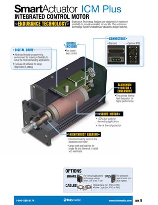
Series ICM Plus
SIZING
ACTUATOR
sizing software
available at www.
tolomatic.com
Motor Speed vs torque
Dimensions
Brake Considerations
An unpowered ICM will require a brake to maintain its position
if an external torque is applied.
A brake can be used with the ICM motor to keep the actuator
from backdriving, typically in vertical applications. A brake may
be used for safety reasons or for energy savings allowing the
actuator to hold position when unpowered.
NOTE: The optional Spring-Applied / Electronically-Released
Brake requires 24V power. It has a input current rating of
0.414 Amps.
0
4
8
12
16
2.00
1.75
1.50
1.25
1.00
0.75
0.50
0.25
0
0
500
1,000
1,500
2,000
2,500
2,900
SPEED (RPM)
TORQUE(in-lb)
TORQUE(N-m)
PEAK
CONTINUOUS
PEAK
CONTINUOUS
24V
48V
24V
48V
3d cad available at
www.tolomatic.com
Test conditions: Motor operated at rated temperature mount-
ed to an aluminum heatsink.Aluminum heatsink: 11 x 11 x 1
⁄2
IP65 CONNECTORSSTANDARD CONNECTORS BRAKE OPTION LENGTH
0.81 [20.6]
KEYWAY
LENGTH
1.500
1.498
38.10
38.05
Ø
Ø
.500
.499
12.70
12.67
Ø
3.23
3.18
KEYWAY
.127
.125
0.430
[10.92]
KEYWAY
Ø4.000
[101.60]
BOLT
CIRCLE
Ø.194
[4.93]
THRU (4)
0.06
[1.5]
1.36
[34.6]
0.30
[7.6]
7.31 [185.8]
0.26 [6.6]
0.47
[11.9]
0.70 [17.9]
3.14
[79.8]
3.14 [79.8]
4.40
[111.9]
0.53
[13.5]
1.22
[31.1]
1.22
[31.1]
1.03
[26.2]
1.03
[26.2]
0.50
[12.6]
0.51
[12.9]
2.09 [53.0]
1.56
[39.5]
2.07
[52.6]
9.38 [238.3]](https://image.slidesharecdn.com/tolomaticicmsmartactuatormotorbrochure-140806132641-phpapp02/85/Tolomatic-icm-smart-actuator-motor-brochure-7-320.jpg)

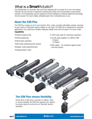
The document discusses the Tolomatic Integrated Control Motor (ICM) Plus, which combines a servo motor, drive, and controller into an integrated smart actuator solution. It can be used with Tolomatic rodless and rod-style electric actuators. The ICM Plus offers flexible operation modes, powerful software, and durable components designed for demanding industrial applications. It provides an affordable and easy to use integrated solution for automation needs.


