The Eclipse Edge provides a cost-effective wireless solution for network edge connections using licensed frequency bands between 7-38GHz. It offers a native mixed mode for both TDM and Ethernet transport over the same radio path at up to 32Mbps. The Eclipse Edge has a low profile and lightweight design for simplified installation, as well as low power consumption below 13W for reduced operational costs.
![Eclipse Edge Datasheet
Harris Stratex Networks and Eclipse are trademarks or registered trademarks
of Harris Stratex Networks Operating Corporation, a wholly owned subsidiary
of Harris Stratex Networks, Inc. and/or its subsidiaries in the United States
and other countries.
© Harris Stratex Networks, Inc. 2008
Data subject to change without notice.
d_etsi_EcliEdge_062108
www.harrisstratex.com
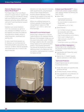
ODUspe Specifications
General
Frequency Band options 7, 13, 15, 18, 23, 38 GHz
ODU Interfaces
IDU to ODU cable (50m & 90m options available with one preterminated end) Shielded Weatherized Cat 5e
Cable length 100 Meters (Maximum)
Connector Connector Weatherproof RJ45 with MDI-X
AGC monitor point BNC
Antenna port Interface ODUspe standard
Polarisation, field selectable ODU rotation
Transmitter Specifications
Transmit Power Tolerance ± 2dB
Transmitter Source Synthesized
Frequency Stability ± 10 ppm
Manual Transmitter Power Control range 15dB
Resolution 1 dB
Accuracy ± 2dB
Automatic Transmitter Power Control Range Configurable over full manual attenuation
Synthesizer Resolution 250 KHz
Receiver Specifications
Receiver Source Synthesized
Frequency Stability 10 PPM
Residual (Background) Bit Error Rate 10-13
RSSI Accuracy [1]
-40 to -70 dBm, 0 to +35° C, ± 2dB
-25 to -85 dBm, -33 to +55° C, ± 4dB
Electrical and Mechanical
Power IEEE 802.3af PoE standard, Class 3 PD, maximum of 12.95W
Size / Weight 255mm x 250 mm x 110 mm / 2.6 kg
ODUspe RF Performance Specifications
System 7 GHz 13 GHz 15 GHz 18 GHz 23 GHz 38 GHz
Frequency Range, GHz 7.125 - 7.9 12.75 - 13.25 14.4 - 15.35 17.7 - 19.7 21.2 - 23.632 37.0 - 39.46
T-R Spacings supported, MHz 150, 154, 161, 168,
175, 196, 245
266 315, 420, 490,
644, 728
1010, 1092.5, 1120 1008, 1200, 1232 1260
Maximum Tuning Range (dependent upon T-R spacing), MHz 56 84 245 380 370 340
System Gain [2]
System Gain at 10-6
BER 4 Mbit/s /2xE1 3.5 MHz 116.0 dB 112.0 dB 112.0 dB 110.0 dB 110.0 dB 106.0 dB
8 Mbit/s /4xE1 7 MHz 114.0 dB 110.0 dB 110.0 dB 108.0 dB 108.0 dB 104.0 dB
16 Mbit/s /8xE1 13.75 / 14 MHz 111.0 dB 107.0 dB 107.0 dB 105.0 dB 105.0 dB 101.0 dB
32 Mbit/s /16xE1 27.5 / 28 MHz 107.0 dB 103.0 dB 103.0 dB 101.0 dB 101.0 dB 97.0 dB
Transmitter Specifications
Power Output, nominal 24.0 dBm 20.0 dBm 20.0 dBm 19.0 dBm 19.0 dBm 17.0 dBm
Receiver Specifications [2]
Threshold at 10-6
BER 4 Mbit/s /2xE1 3.5 MHz -92.0 dBm -92.0 dBm -92.0 dBm -91.0 dBm -91.0 dBm -89.0 dBm
8 Mbit/s /4xE1 7 MHz -90.0 dBm -90.0 dBm -90.0 dBm -89.0 dBm -89.0 dBm -87.0 dBm
16 Mbit/s /8xE1 13.75 / 14 MHz -87.0 dBm -87.0 dBm -87.0 dBm -86.0 dBm -86.0 dBm -84.0 dBm
32 Mbit/s /16xE1 27.5 / 28 MHz -83.0 dBm -83.0 dBm -83.0 dBm -82.0 dBm -82.0 dBm -80.0 dBm
All specifications are preliminary typical values unless otherwise stated, and are subject to change without notice.
[1] RSSI accuracy is only valid when there is no unwanted signal or potential interferer present within ±28MHz of the RX frequency.
[2] System Gain and Rx Threshold values are for BER=10-6
. Values for BER=10-3
are improved by 1dB.](https://image.slidesharecdn.com/eclipseedgedatasheet-130611024739-phpapp02/85/Eclipse-edge-datasheet-4-320.jpg)


![5G Explained! A High Level Overview [Introduction]](https://cdn.slidesharecdn.com/ss_thumbnails/5gexplainedahighleveloverview-260119165306-cc137a3e-thumbnail.jpg?width=640&height=640&fit=bounds)


