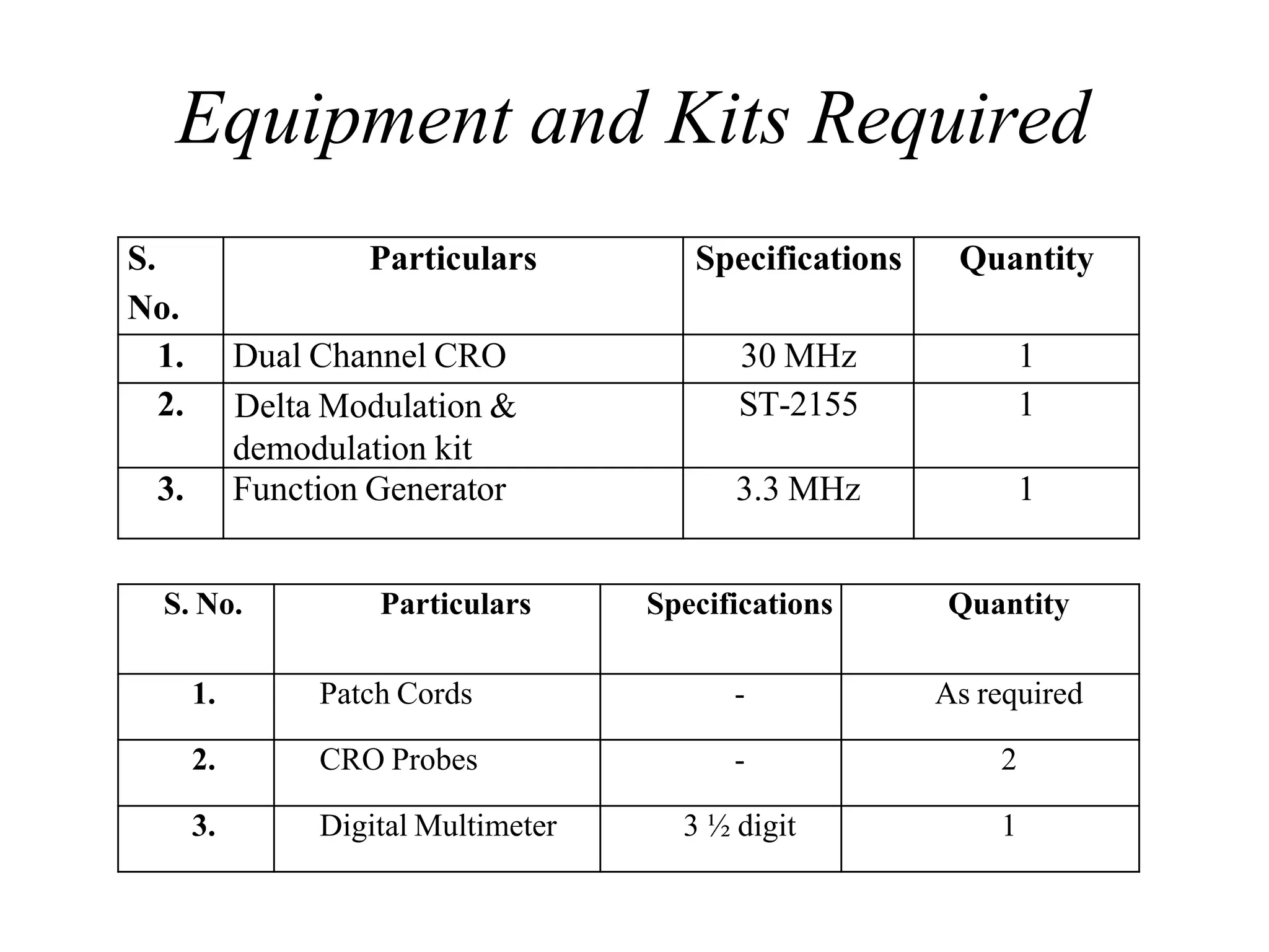
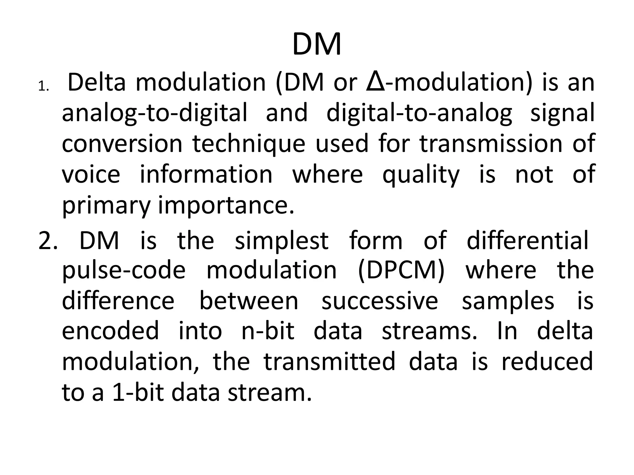
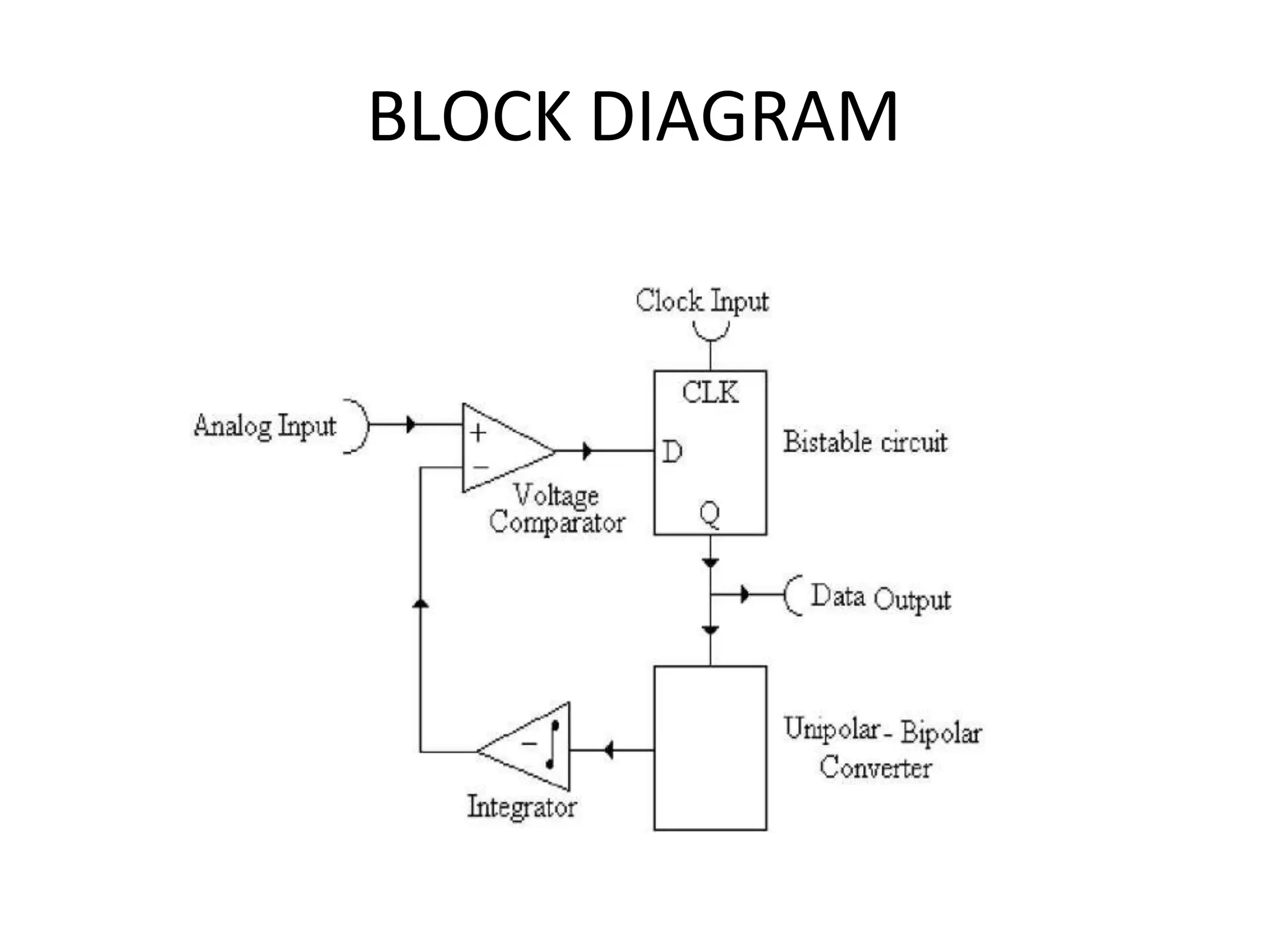
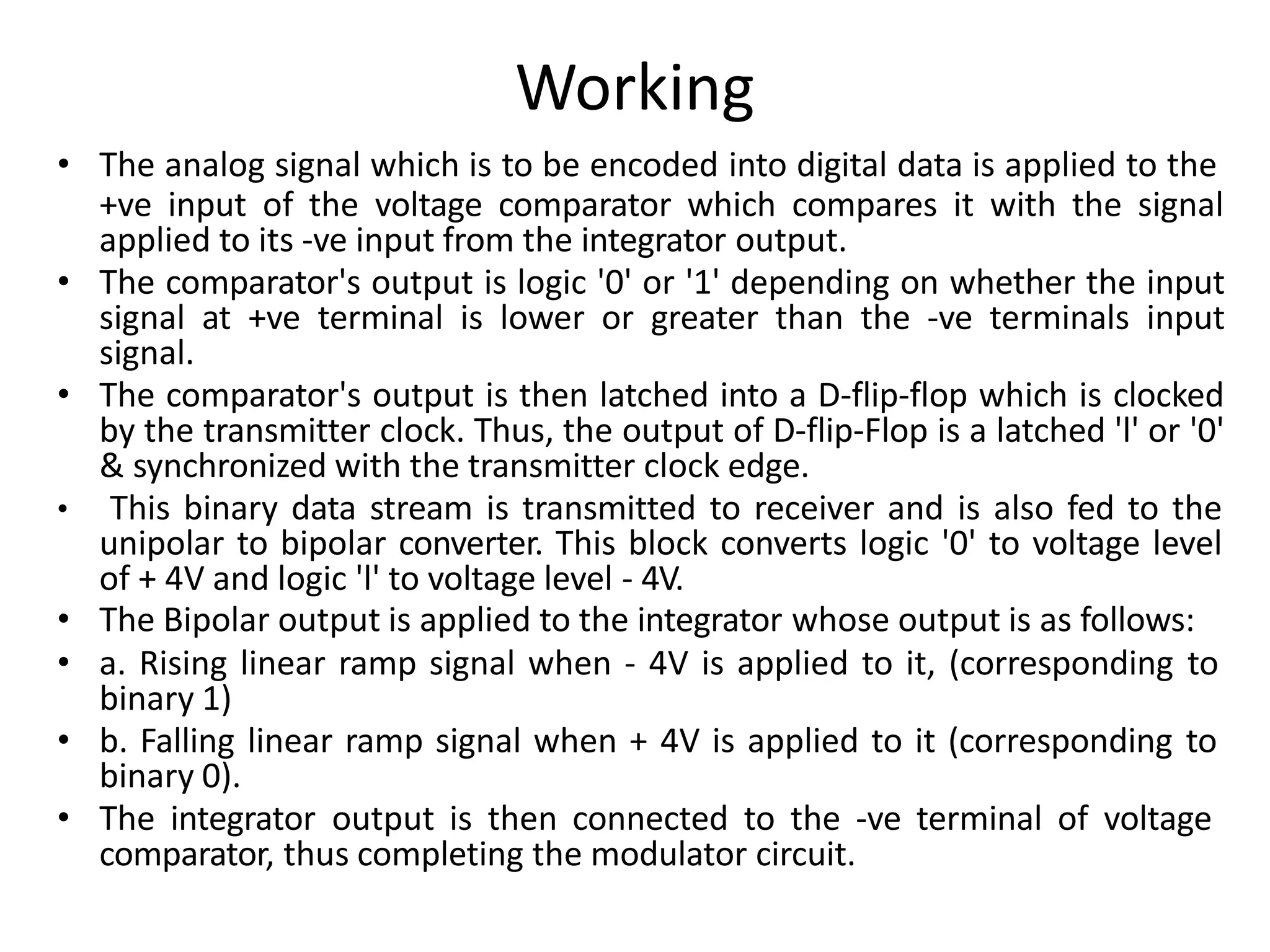
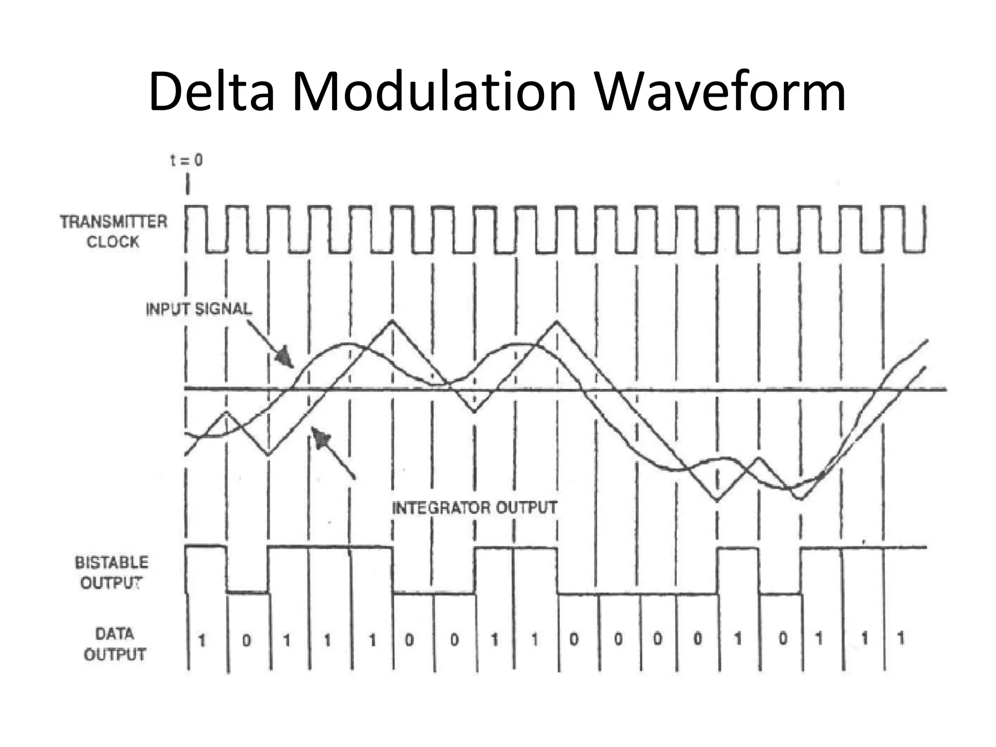
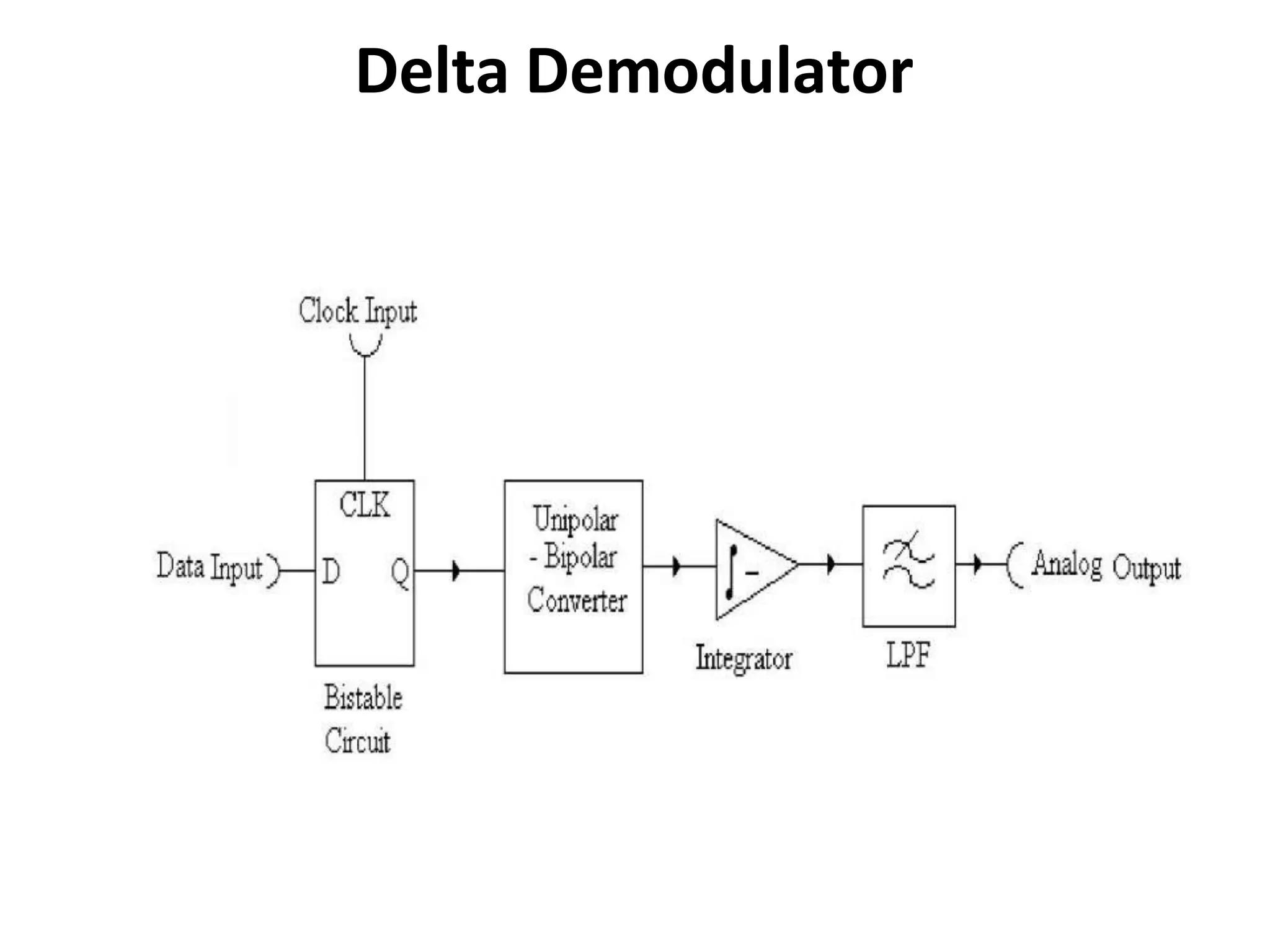
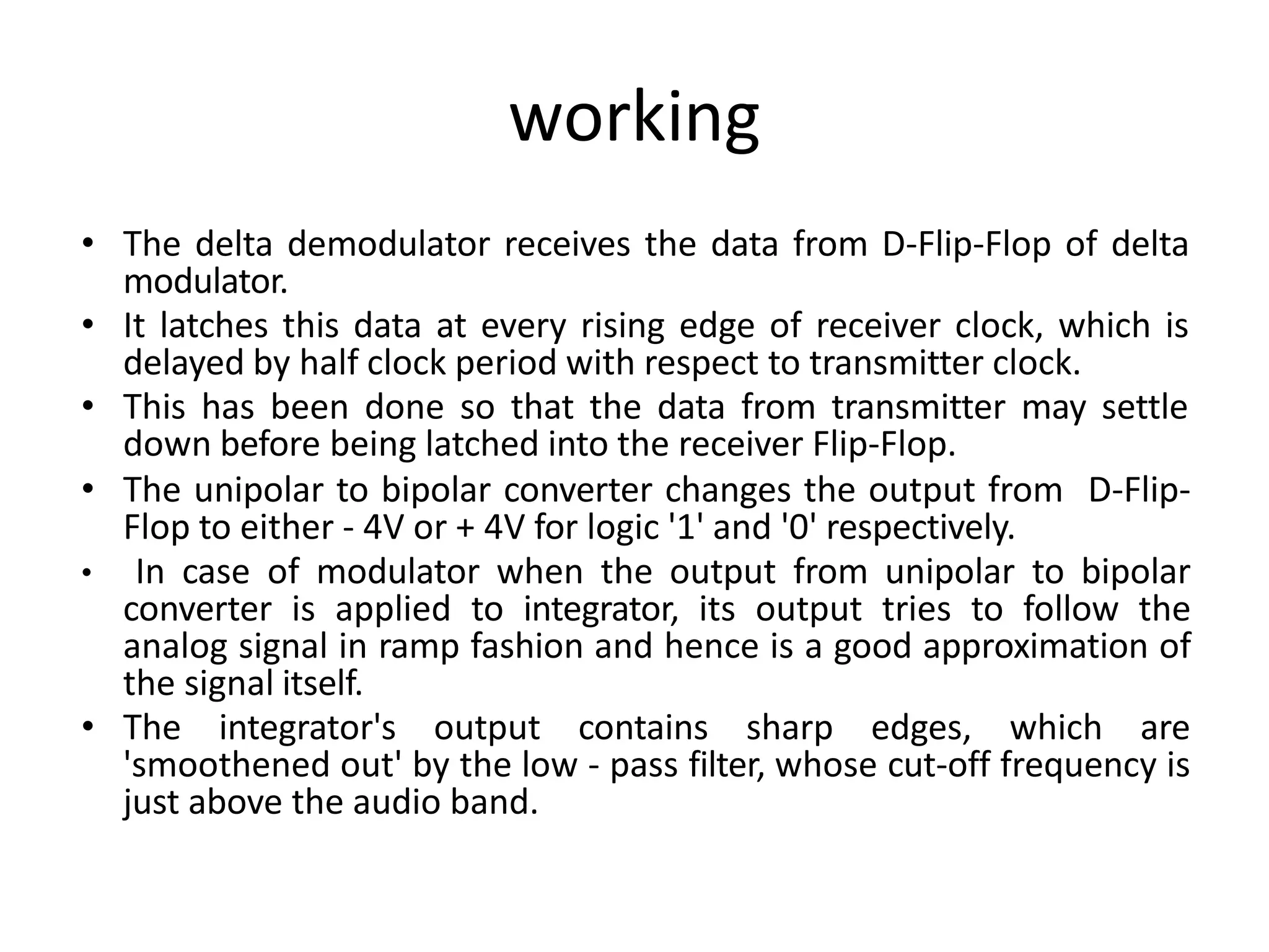
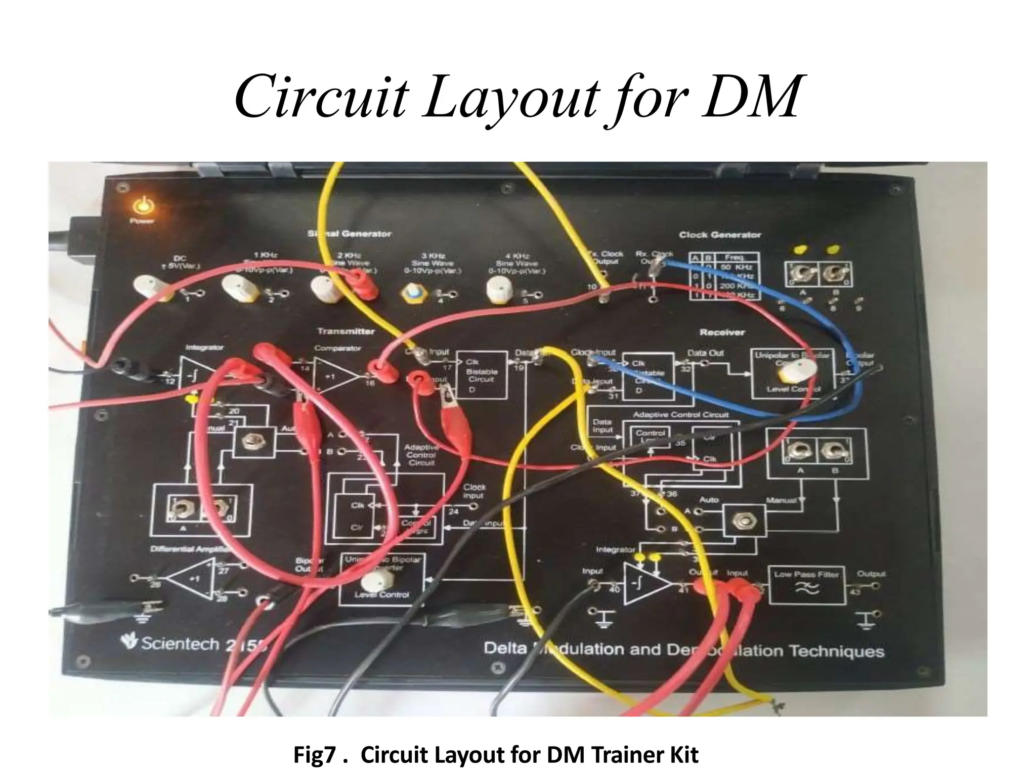
KEC 651
Digital Communications Lab
EXPERIMENT-07
To study Delta Modulation and
Demodulation and also observe
the effect of slope overload.
1
Outline
□ Introduction
□ Equipment and Kits Required
□ Delta Modulation and
□ Delta Demodulation
2
Equipment and Kits Required
S.
No.
Particulars Specifications Quantity
1. Dual Channel CRO 30 MHz 1
2. Delta Modulation &
demodulation kit
ST-2155 1
3. Function Generator 3.3 MHz 1
S. No. Particulars Specifications Quantity
1. Patch Cords - As required
2. CRO Probes - 2
3. Digital Multimeter 3 ½ digit 1
DM
1. Delta modulation (DM or Δ-modulation) is an
analog-to-digital and digital-to-analog signal
conversion technique used for transmission of
voice information where quality is not of
primary importance.
2. DM is the simplest form of differential
pulse-code modulation (DPCM)
difference between successive
where the
samples is
encoded into n-bit data streams. In delta
modulation, the transmitted data is reduced
to a 1-bit data stream.
BLOCK DIAGRAM
Working
• The analog signal which is to be encoded into digital data is applied to the
+ve input of the voltage comparator which compares it with the signal
applied to its -ve input from the integrator output.
• The comparator's output is logic '0' or '1' depending on whether the input
signal at +ve terminal is lower or greater than the -ve terminals input
signal.
• The comparator's output is then latched into a D-flip-flop which is clocked
by the transmitter clock. Thus, the output of D-flip-Flop is a latched 'l' or '0'
& synchronized with the transmitter clock edge.
• This binary data stream is transmitted to receiver and is also fed to the
unipolar to bipolar converter. This block converts logic '0' to voltage level
of + 4V and logic 'l' to voltage level - 4V.
• The Bipolar output is applied to the integrator whose output is as follows:
• a. Rising linear ramp signal when - 4V is applied to it, (corresponding to
binary 1)
• b. Falling linear ramp signal when + 4V is applied to it (corresponding to
binary 0).
• The integrator output is then connected to the -ve terminal of voltage
comparator, thus completing the modulator circuit.
Delta Modulation Waveform
Delta Demodulator
working
• The delta demodulator receives the data from D-Flip-Flop of delta
modulator.
• It latches this data at every rising edge of receiver clock, which is
delayed by half clock period with respect to transmitter clock.
• This has been done so that the data from transmitter may settle
down before being latched into the receiver Flip-Flop.
• The unipolar to bipolar converter changes the output from D-Flip-
Flop to either - 4V or + 4V for logic '1' and '0' respectively.
• In case of modulator when the output from unipolar to bipolar
converter is applied to integrator, its output tries to follow the
analog signal in ramp fashion and hence is a good approximation of
the signal itself.
• The integrator's output contains sharp edges, which are
'smoothened out' by the low - pass filter, whose cut-off frequency is
just above the audio band.
Circuit Layout for DM
Fig7 . Circuit Layout for DM Trainer Kit

To study Delta Modulation and Demodulation and also observe the effect of slope overload.

  • 1.
    KEC 651 Digital CommunicationsLab EXPERIMENT-07 To study Delta Modulation and Demodulation and also observe the effect of slope overload. 1
  • 2.
    Outline □ Introduction □ Equipmentand Kits Required □ Delta Modulation and □ Delta Demodulation 2
  • 3.
    Equipment and KitsRequired S. No. Particulars Specifications Quantity 1. Dual Channel CRO 30 MHz 1 2. Delta Modulation & demodulation kit ST-2155 1 3. Function Generator 3.3 MHz 1 S. No. Particulars Specifications Quantity 1. Patch Cords - As required 2. CRO Probes - 2 3. Digital Multimeter 3 ½ digit 1
  • 4.
    DM 1. Delta modulation(DM or Δ-modulation) is an analog-to-digital and digital-to-analog signal conversion technique used for transmission of voice information where quality is not of primary importance. 2. DM is the simplest form of differential pulse-code modulation (DPCM) difference between successive where the samples is encoded into n-bit data streams. In delta modulation, the transmitted data is reduced to a 1-bit data stream.
  • 5.
  • 6.
    Working • The analogsignal which is to be encoded into digital data is applied to the +ve input of the voltage comparator which compares it with the signal applied to its -ve input from the integrator output. • The comparator's output is logic '0' or '1' depending on whether the input signal at +ve terminal is lower or greater than the -ve terminals input signal. • The comparator's output is then latched into a D-flip-flop which is clocked by the transmitter clock. Thus, the output of D-flip-Flop is a latched 'l' or '0' & synchronized with the transmitter clock edge. • This binary data stream is transmitted to receiver and is also fed to the unipolar to bipolar converter. This block converts logic '0' to voltage level of + 4V and logic 'l' to voltage level - 4V. • The Bipolar output is applied to the integrator whose output is as follows: • a. Rising linear ramp signal when - 4V is applied to it, (corresponding to binary 1) • b. Falling linear ramp signal when + 4V is applied to it (corresponding to binary 0). • The integrator output is then connected to the -ve terminal of voltage comparator, thus completing the modulator circuit.
  • 7.
  • 8.
  • 9.
    working • The deltademodulator receives the data from D-Flip-Flop of delta modulator. • It latches this data at every rising edge of receiver clock, which is delayed by half clock period with respect to transmitter clock. • This has been done so that the data from transmitter may settle down before being latched into the receiver Flip-Flop. • The unipolar to bipolar converter changes the output from D-Flip- Flop to either - 4V or + 4V for logic '1' and '0' respectively. • In case of modulator when the output from unipolar to bipolar converter is applied to integrator, its output tries to follow the analog signal in ramp fashion and hence is a good approximation of the signal itself. • The integrator's output contains sharp edges, which are 'smoothened out' by the low - pass filter, whose cut-off frequency is just above the audio band.
  • 10.
    Circuit Layout forDM Fig7 . Circuit Layout for DM Trainer Kit