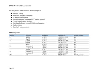
TN 566 Practice Skills Assessment
Page | 1
Skill integration challenge
In this activity, there are 2 parts include. The first part is, recover the routers with different defects. In the second part, you will implement
Cisco real lab scenario using those recovered routers. Instructions will be given to each student when you finish first part of this
assignment.
Part 1
You have been provided four Cisco 2600 series routers with different deficits. Each router has more than one defects. (Ex- corrupted
image (IOS) on the flash and inconsistence baud rate). Each student is assigned to Four of these routers and they must come up with
solutions to recover the router.
Router 1 stuck in ROMON mode. Recover router from ROMON mode and boot router with cisco IOS.
Router 2 needs enable password recovery.
Router 3 terminal session does not load properly in the terminal emulator screen.
Router 4 does lose its startup configurations during the reboot. Come up with solution to fix that problem. Then you need to upgrade
IOS in to 12.2 version.
Part 2
Background
In this Lab Scenario, you have been provided with four Cisco 2600 series routers, one Cisco 2950 series switch and one Windows 7
professional loaded computer. You will practice skills necessary for navigating the Cisco IOS commands and Physical cabling. You
will all so implement multi area OSPF version 2 routing protocol, Hot Standby Router Protocol (HSRP) and redistribute routes between
OSPF, EIGRP, RIP/V2 and Static routes. Finally, you will test the connectivity by using loopback interfaces.
All cisco routers and switch IOS configurations should be done through terminal connection to the device console.
TN 566 Practice Skills Assessment
Page | 2
Topology
TN 566 Practice Skills Assessment
Page | 3
You will practice and evaluates on the following skills
 Physical cabling
 Configure basic IOS commands
 IP address configuration
 Implementation of multi area OSPF routing protocol
 Virtual routs between networks.
 Hot Standby Router Protocol (HSRP) configuration.
 Redistribution
 Loopback test connectivity
Addressing table
Device Interface IP address Subnet Mask Default gateway
R1 Se0/0/0 10.10.3.1 255.255.255.252 N/A
Gig0/0 10.10.1.1 255.255.255.0 N/A
R2 Se0/0/0 10.10.2.1 255.255.255.252 N/A
Gig0/0 10.10.1.2 255.255.255.0 N/A
R3
Se0/0/1 10.10.2.2 255.255.255.252 N/A
Loopback 1 172.0.0.1 255.255.255.255 N/A
Loopback 2 172.0.0.2 255.255.255.255 N/A
R4
Se0/0/0 10.10.3.2 255.255.255.252 N/A
Loopback 1 172.0.0.3 255.255.255.255 N/A
Loopback 2 172.0.0.4 255.255.255.255 N/A
PC1 NIC 10.10.1.4 255.255.255.0 Default gateway
TN 566 Practice Skills Assessment
Page | 4
Requirements
You are required to complete the following steps. You will not be given all the steps to complete this activity. You will use your TN275,
TN375, TN475 knowledge to complete this activity.
Some values that are required to complete the configurations have not been given to you. In those cases, create the values that
you need to complete the steps. These values may include certain IP addresses, interface descriptions, MOTD banner, and
process IDs.
Step 1: Design this physical network using real cisco 2600 routers and switch base on the topology which is given above.
Step 2: Configuration of initial device settings such as host name and MOTD banner.
Step 3: Use the addressing table to configure router’s IP interfaces. Configure a description for each interface to help document the
network information.
Step 4: Configure multi area OSPF version 2 protocol in routers and test the connectivity between R3 and R4.
Step 5: Configure PC1 in order to involve network connectivity with routers. Test connectivity between PC1 and routers.
Step 6: Use the addressing table to configure loopback interfaces on R3 and R4. Each loop back interfaces are advertised like below.
1. Interface Loopback1 advertise in EIGRP
2. Interface Loopback2 advertise in OSPF
3. Interface Loopback3 advertise in RIP/V2
4. Interface Loopback4 advertise in Static
Step 7: Test connectivity between PC1 and Loopback addresses. Perform these test commands.
 Ping 172.0.0.1
 Ping 172.0.0.2
 Ping 172.0.0.3
 Ping 172.0.0.4

TN566 labs

  • 1.
    TN 566 PracticeSkills Assessment Page | 1 Skill integration challenge In this activity, there are 2 parts include. The first part is, recover the routers with different defects. In the second part, you will implement Cisco real lab scenario using those recovered routers. Instructions will be given to each student when you finish first part of this assignment. Part 1 You have been provided four Cisco 2600 series routers with different deficits. Each router has more than one defects. (Ex- corrupted image (IOS) on the flash and inconsistence baud rate). Each student is assigned to Four of these routers and they must come up with solutions to recover the router. Router 1 stuck in ROMON mode. Recover router from ROMON mode and boot router with cisco IOS. Router 2 needs enable password recovery. Router 3 terminal session does not load properly in the terminal emulator screen. Router 4 does lose its startup configurations during the reboot. Come up with solution to fix that problem. Then you need to upgrade IOS in to 12.2 version. Part 2 Background In this Lab Scenario, you have been provided with four Cisco 2600 series routers, one Cisco 2950 series switch and one Windows 7 professional loaded computer. You will practice skills necessary for navigating the Cisco IOS commands and Physical cabling. You will all so implement multi area OSPF version 2 routing protocol, Hot Standby Router Protocol (HSRP) and redistribute routes between OSPF, EIGRP, RIP/V2 and Static routes. Finally, you will test the connectivity by using loopback interfaces. All cisco routers and switch IOS configurations should be done through terminal connection to the device console.
  • 2.
    TN 566 PracticeSkills Assessment Page | 2 Topology
  • 3.
    TN 566 PracticeSkills Assessment Page | 3 You will practice and evaluates on the following skills  Physical cabling  Configure basic IOS commands  IP address configuration  Implementation of multi area OSPF routing protocol  Virtual routs between networks.  Hot Standby Router Protocol (HSRP) configuration.  Redistribution  Loopback test connectivity Addressing table Device Interface IP address Subnet Mask Default gateway R1 Se0/0/0 10.10.3.1 255.255.255.252 N/A Gig0/0 10.10.1.1 255.255.255.0 N/A R2 Se0/0/0 10.10.2.1 255.255.255.252 N/A Gig0/0 10.10.1.2 255.255.255.0 N/A R3 Se0/0/1 10.10.2.2 255.255.255.252 N/A Loopback 1 172.0.0.1 255.255.255.255 N/A Loopback 2 172.0.0.2 255.255.255.255 N/A R4 Se0/0/0 10.10.3.2 255.255.255.252 N/A Loopback 1 172.0.0.3 255.255.255.255 N/A Loopback 2 172.0.0.4 255.255.255.255 N/A PC1 NIC 10.10.1.4 255.255.255.0 Default gateway
  • 4.
    TN 566 PracticeSkills Assessment Page | 4 Requirements You are required to complete the following steps. You will not be given all the steps to complete this activity. You will use your TN275, TN375, TN475 knowledge to complete this activity. Some values that are required to complete the configurations have not been given to you. In those cases, create the values that you need to complete the steps. These values may include certain IP addresses, interface descriptions, MOTD banner, and process IDs. Step 1: Design this physical network using real cisco 2600 routers and switch base on the topology which is given above. Step 2: Configuration of initial device settings such as host name and MOTD banner. Step 3: Use the addressing table to configure router’s IP interfaces. Configure a description for each interface to help document the network information. Step 4: Configure multi area OSPF version 2 protocol in routers and test the connectivity between R3 and R4. Step 5: Configure PC1 in order to involve network connectivity with routers. Test connectivity between PC1 and routers. Step 6: Use the addressing table to configure loopback interfaces on R3 and R4. Each loop back interfaces are advertised like below. 1. Interface Loopback1 advertise in EIGRP 2. Interface Loopback2 advertise in OSPF 3. Interface Loopback3 advertise in RIP/V2 4. Interface Loopback4 advertise in Static Step 7: Test connectivity between PC1 and Loopback addresses. Perform these test commands.  Ping 172.0.0.1  Ping 172.0.0.2  Ping 172.0.0.3  Ping 172.0.0.4