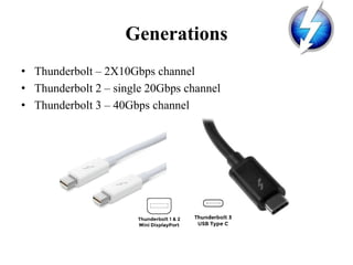
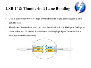
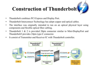
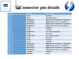
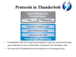
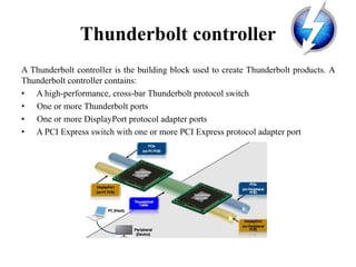
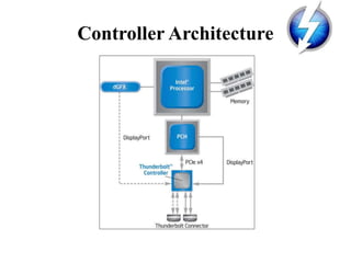
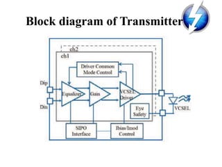
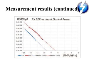
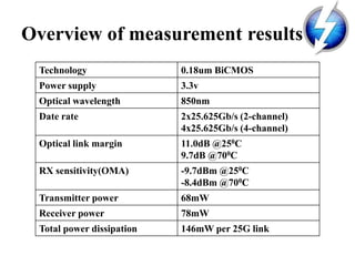
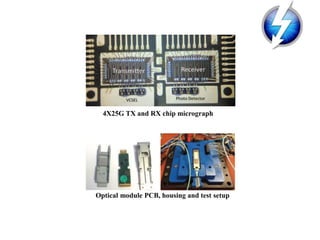
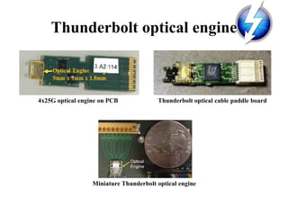
SAMBHRAM INSTITUTE OF TECHNOLOGY, BENGALURU
Department of Electronics & Communication Engineering
SEMINAR Presentation
on
THUNDERBOLT
Presentation by
PRAVEEN KUMAR C (1ST13EC725)
VIII Semester B.E.
Seminar coordinator Class Coordinator
Dr. C.V. Ravishankar S. Sowndeswari
HOD, Dept of ECE, SaIT Asst.Prof. Dept. ECE, SaIT
Contents
• Introduction
• Copper V/s Optical
• Generations
• Construction of Thunderbolt
• Connector pin details
• Protocol in Thunderbolt
• Thunderbolt control
• Thunderbolt transmitter
• Thunderbolt Receiver
• Measurement Results
• Key Features
• Conclusion & Future works
• References
Introduction
• Thunderbolt began in Intel labs with a simple concept to create an incredibly fast
input/output technology.
• Thunderbolt emerged from the lab to make its appearance in Mac computers after
technical collaboration between Intel and Apple.
• Thunderbolt is originally codenamed as “Light Peak”.
• It is an interface for connecting peripheral devices to a computer via an expansion
bus.
• Though initially registered with Apple Inc., full rights of the Thunderbolt
technology trademark belong to Intel Corp.,
• It is identical to normal Display Port connector.
Copper V/s Optical
Transmission Media Copper Optical
No. of Channels 2-4 2-4
Transmission rate per
channel
10Gbps 10 – 20Gbps
Transmission capacity 20-40Gbps 20-40Gbps
Cable Length 0.3m, 0.5m, 1m
1.5m, 2.0m, 3.0m
10m, 20m, 30m, 60m
Connector size 28mm 38mm
Bus power supply 15W None
Hot pluggable Yes Yes
Max voltage 18v No
Connector Type Mini DisplayPort,
USB Type-C
Mini DisplayPort,
USB Type-C
Maximum Current 550mA – 1A None
Daisy-Chain Upto 6 devices Upto 6 devices
Generations
• Thunderbolt – 2X10Gbps channel
• Thunderbolt 2 – single 20Gbps channel
• Thunderbolt 3 – 40Gbps channel
USB-C & Thunderbolt Lane Bonding
• USB-C connectors provide 4 high-speed differential signal paths clockable up to
20Gbps each.
• Thunderbolt 3 controllers bond two lanes in each direction at 10Gbps or 20Gbps to
create either two 20Gbps or 40Gbps links, enabling high-speed data transfers in
each direction simultaneously.
Construction of Thunderbolt
• Thunderbolt combines PCI Express and Display Port.
• Thunderbolt Interconnect Technology has adopt copper and optical cables.
• The interface was originally intended to run on an optical physical layer using
components and flexible optical fiber cabling.
• Thunderbolt 1 & 2 is provided 20pin connector similar to Mini-DisplayPort and
Thunderbolt3 provides 24pin type-C connector.
• It consist of Transmitter and Receiver IC with Thunderbolt controller.
Connector pin details
Protocols in Thunderbolt
• In thunderbolt, both PCIe signal and DisplayPort signal are transferred through
same cable based on the switched fabric architecture with full-duplex links.
• The heart of the Thunderbolt protocol architecture is the transport layer.
Thunderbolt controller
A Thunderbolt controller is the building block used to create Thunderbolt products. A
Thunderbolt controller contains:
• A high-performance, cross-bar Thunderbolt protocol switch
• One or more Thunderbolt ports
• One or more DisplayPort protocol adapter ports
• A PCI Express switch with one or more PCI Express protocol adapter port
Controller Architecture
Block diagram of Transmitter
Transmitter Circuit
Block Diagram of Receiver
Receiver circuit
Measurement results
Measurement results (continued)
Overview of measurement results
Technology 0.18um BiCMOS
Power supply 3.3v
Optical wavelength 850nm
Date rate 2x25.625Gb/s (2-channel)
4x25.625Gb/s (4-channel)
Optical link margin 11.0dB @250C
9.7dB @700C
RX sensitivity(OMA) -9.7dBm @250C
-8.4dBm @700C
Transmitter power 68mW
Receiver power 78mW
Total power dissipation 146mW per 25G link
4X25G TX and RX chip micrograph
Optical module PCB, housing and test setup
4x25G optical engine on PCB Thunderbolt optical cable paddle board
Miniature Thunderbolt optical engine
Thunderbolt optical engine
Key features
• 20-40Gbps channel.
• Bi-directional
• Dual-protocol (PCI Express and Display Port)
• Compatible with existing Display Port devices except Thunderbolt 3.
• Electrical or optical cables.
• Daisy-chained devices.
• Low latency with highly accurate time synchronization.
• Use native protocol software drivers.
• Power over cable for bus-powered devices.
Thunderbolt v/s FireWire 800 v/s
USB
Capability of Thunderbolt
Conclusion
• Thunderbolt technology brings a new balance of performance, simplicity and
flexibility to end users and product designers alike
• Due to cost factor, it is out of reach for an average product for now, USB still more
popular which practically free
• At present it is running at electrical standard but it will be at optical standard in
long run
References
• Jerry Gao, Hengju Cheng, Hui-Chin Wu, Guobin Liu. Edmond Lau, Li Yuan,
Christine Krause, “Thunderbolt Interconnect – Optical and copper”, IEEE journal
of Lightwave Technology, 2016.
• J. Gao, H. Cheng, H. Wu, G. Liu, E. Lau, Li Yuan, C. Krause, “2X25G Low Power
Optical IC for Thunderbolt Optical Cable Technology”, IEEE journal, 2016.
Thank You !

Thunderbolt

  • 1.
    SAMBHRAM INSTITUTE OFTECHNOLOGY, BENGALURU Department of Electronics & Communication Engineering SEMINAR Presentation on THUNDERBOLT Presentation by PRAVEEN KUMAR C (1ST13EC725) VIII Semester B.E. Seminar coordinator Class Coordinator Dr. C.V. Ravishankar S. Sowndeswari HOD, Dept of ECE, SaIT Asst.Prof. Dept. ECE, SaIT
  • 2.
    Contents • Introduction • CopperV/s Optical • Generations • Construction of Thunderbolt • Connector pin details • Protocol in Thunderbolt • Thunderbolt control • Thunderbolt transmitter • Thunderbolt Receiver • Measurement Results • Key Features • Conclusion & Future works • References
  • 3.
    Introduction • Thunderbolt beganin Intel labs with a simple concept to create an incredibly fast input/output technology. • Thunderbolt emerged from the lab to make its appearance in Mac computers after technical collaboration between Intel and Apple. • Thunderbolt is originally codenamed as “Light Peak”. • It is an interface for connecting peripheral devices to a computer via an expansion bus. • Though initially registered with Apple Inc., full rights of the Thunderbolt technology trademark belong to Intel Corp., • It is identical to normal Display Port connector.
  • 4.
    Copper V/s Optical TransmissionMedia Copper Optical No. of Channels 2-4 2-4 Transmission rate per channel 10Gbps 10 – 20Gbps Transmission capacity 20-40Gbps 20-40Gbps Cable Length 0.3m, 0.5m, 1m 1.5m, 2.0m, 3.0m 10m, 20m, 30m, 60m Connector size 28mm 38mm Bus power supply 15W None Hot pluggable Yes Yes Max voltage 18v No Connector Type Mini DisplayPort, USB Type-C Mini DisplayPort, USB Type-C Maximum Current 550mA – 1A None Daisy-Chain Upto 6 devices Upto 6 devices
  • 5.
    Generations • Thunderbolt –2X10Gbps channel • Thunderbolt 2 – single 20Gbps channel • Thunderbolt 3 – 40Gbps channel
  • 6.
    USB-C & ThunderboltLane Bonding • USB-C connectors provide 4 high-speed differential signal paths clockable up to 20Gbps each. • Thunderbolt 3 controllers bond two lanes in each direction at 10Gbps or 20Gbps to create either two 20Gbps or 40Gbps links, enabling high-speed data transfers in each direction simultaneously.
  • 7.
    Construction of Thunderbolt •Thunderbolt combines PCI Express and Display Port. • Thunderbolt Interconnect Technology has adopt copper and optical cables. • The interface was originally intended to run on an optical physical layer using components and flexible optical fiber cabling. • Thunderbolt 1 & 2 is provided 20pin connector similar to Mini-DisplayPort and Thunderbolt3 provides 24pin type-C connector. • It consist of Transmitter and Receiver IC with Thunderbolt controller.
  • 8.
  • 9.
    Protocols in Thunderbolt •In thunderbolt, both PCIe signal and DisplayPort signal are transferred through same cable based on the switched fabric architecture with full-duplex links. • The heart of the Thunderbolt protocol architecture is the transport layer.
  • 10.
    Thunderbolt controller A Thunderboltcontroller is the building block used to create Thunderbolt products. A Thunderbolt controller contains: • A high-performance, cross-bar Thunderbolt protocol switch • One or more Thunderbolt ports • One or more DisplayPort protocol adapter ports • A PCI Express switch with one or more PCI Express protocol adapter port
  • 11.
  • 12.
    Block diagram ofTransmitter
  • 13.
  • 14.
  • 15.
  • 16.
  • 17.
  • 18.
    Overview of measurementresults Technology 0.18um BiCMOS Power supply 3.3v Optical wavelength 850nm Date rate 2x25.625Gb/s (2-channel) 4x25.625Gb/s (4-channel) Optical link margin 11.0dB @250C 9.7dB @700C RX sensitivity(OMA) -9.7dBm @250C -8.4dBm @700C Transmitter power 68mW Receiver power 78mW Total power dissipation 146mW per 25G link
  • 19.
    4X25G TX andRX chip micrograph Optical module PCB, housing and test setup
  • 20.
    4x25G optical engineon PCB Thunderbolt optical cable paddle board Miniature Thunderbolt optical engine Thunderbolt optical engine
  • 21.
    Key features • 20-40Gbpschannel. • Bi-directional • Dual-protocol (PCI Express and Display Port) • Compatible with existing Display Port devices except Thunderbolt 3.
  • 22.
    • Electrical oroptical cables. • Daisy-chained devices. • Low latency with highly accurate time synchronization. • Use native protocol software drivers. • Power over cable for bus-powered devices.
  • 23.
  • 24.
  • 25.
    Conclusion • Thunderbolt technologybrings a new balance of performance, simplicity and flexibility to end users and product designers alike • Due to cost factor, it is out of reach for an average product for now, USB still more popular which practically free • At present it is running at electrical standard but it will be at optical standard in long run
  • 26.
    References • Jerry Gao,Hengju Cheng, Hui-Chin Wu, Guobin Liu. Edmond Lau, Li Yuan, Christine Krause, “Thunderbolt Interconnect – Optical and copper”, IEEE journal of Lightwave Technology, 2016. • J. Gao, H. Cheng, H. Wu, G. Liu, E. Lau, Li Yuan, C. Krause, “2X25G Low Power Optical IC for Thunderbolt Optical Cable Technology”, IEEE journal, 2016.
  • 27.