Download to read offline


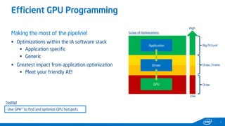
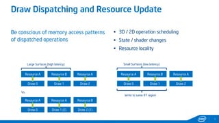

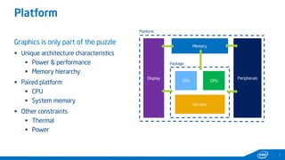
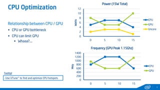
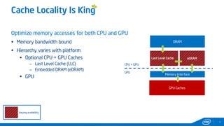

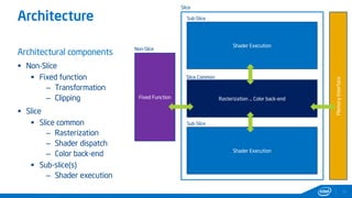
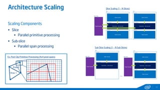
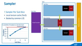

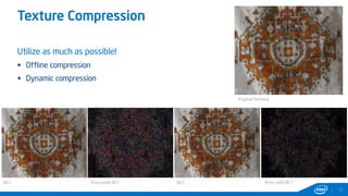
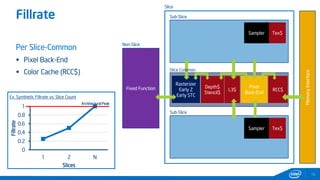
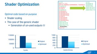


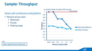

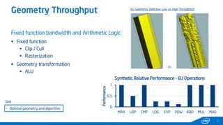


This document provides tips and tricks for achieving the best performance with Intel graphics. It discusses optimizing various aspects of an application including the platform, sampler, fillrate, arithmetic logic, and geometry. It emphasizes starting optimizations at the application level and being conscious of memory access patterns and cache locality. It also discusses scaling a game across different platforms by establishing performance ceilings and optimizing for varying memory bandwidth, sampler throughput, fillrate, and geometry throughput. The overall goal is to create a game that runs well on a wide range of systems.