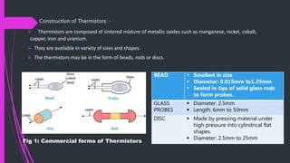
THERMISTORS
BY
SHIWANI RAJ
CONTENTS
 INTRODUCTION OF THERMISTORS
 TYPES OF THERMISTORS
 CONSTRUCTION OF THERMISTORS
 CHARACTERISTICS OF THERMISTORS
 RESISTANCE-TEMPERATURE CHARACTERISTICS
 VOLTAGE-CURRENT CHARACTERISTICS
 CURRENT-TIME CHARACTERISTICS
 ADVANTAGES, DISADVANTAGES AND APPLICATION OF THERMISTORS
 REFERENCE
Thermistors
 Thermistors is a contraction of term “Thermal Resistors”.
 Thermistors are essentially semiconductors which behave as resistors with
a high negative temperature coefficient of resistance.
 In some cases the resistance of a thermistor at room temperature may
decrease as much as 5 per cent for each 1° C rise in temperature. This high
sensitivity to temperature changes make the thermistors extremely useful
for precision temperature measurements, control and compensation.
 Thermistors are widely used in the temperature range of -60°C to +15°C.
 The resistance of thermistors ranges from 0.5 Ω to 0.75 Ω.
TYPES OF THERMISTORS
Thermistors are of basically two types:
1. NTC Type: Where the resistance decreases with an
increase in temperature.
2. PTC Type: Where the resistance increases with an
increase in temperature.
 NOTE: NTC stands for Negative Temperature Coefficient and PTC stands for Positive
Temperature Coefficient.
Construction of Thermistors: -
 Thermistors are composed of sintered mixture of metallic oxides such as manganese, nickel, cobalt,
copper, iron and uranium.
 They are available in variety of sizes and shapes.
 The thermistors may be in the form of beads, rods or discs.
Fig 1: Commercial forms of Thermistors
BEAD  Smallest in size
 Diameter: 0.015mm to1.25mm
 Sealed in tips of solid glass rods
to form probes.
GLASS
PROBES
 Diameter: 2.5mm
 Length: 6mm to 50mm
DISC  Made by pressing material under
high pressure into cylindrical flat
shapes.
 Diameter: 2.5mm to 25mm
CHARACTERISTICS OF THERMISTORS
 There are three important characteristics of thermistors given below:
1. Resistance-Temperature Characteristics
2. Voltage-Current Characteristics
3. Current-Time Characteristics
Resistance-Temperature Characteristics
 The resistance-temperature characteristics of thermistor is
non- linear.
 The resistance-temperature characteristics show that a
thermistor has a very high negative temperature co-efficient of
resistance, making it an ideal temperature transducer.
 The resistance-temperature characteristics show that even for a
small change in temperature the change in resistance of a
thermistor is very large.
 Between -100°C and 400°C, the thermistor changes its resistivity
from 10-7 to 10 Ω cm, a factor of 107.
FIG 2: Resistance-temperature
characteristics of a typical thermistor and
platinum
 The mathematical expression for the relationship between the resistance of a thermistor and absolute
temperature of thermistor is
 RT1 = RT2 exp. [ β (
1
𝑇1
-
1
𝑇2
) ]
where RT1 = resistance of the thermistor at absolute temperature T1 K,
RT2 = resistance of the thermistor at absolute temperature T2 K,
and β = a constant depending upon the material of thermistor, typically 3500 to 4500 K
 A linear approximation of the resistance-temperature curve can be obtained over a small range of
temperatures. For a limited range of temperature, the resistance of a thermistor is given as
 RT1 = RT2 [1 + αT1 ∆T]
where α = the temperature coefficient of the resistance which is typically
0.05 Ω/Ω - °C
∆T = Change in temperature = T2 – T1
 An approximate logarithmic relationship used for resistance-temperature relationship for a thermistor is
given as:
 RT = aR0 eb/T
where RT = resistance at temperature T K, R0 = resistance at temperature T K, a and b are constants
NOTE: A linear approximation means that we may develop an equation for a straight light which approximates the
resistance versus temperature curve over a specified span.
VOLTAGE-CURRENT CHARACTERISTICS
 If the applied voltage to a thermistor is small, the current is
small and the thermistor obeys Ohm’s law. At low voltage
current is proportional to voltage. When the current in the
thermistor is large enough to raise the temperature of the
thermistor appreciably above the ambient temperature,
the resistance of the thermistor will be decreased and
more current will flow, further increasing the temperature
and decreasing the resistance of the thermistor. This
current increases until the heat dissipation of the
thermistor equals the electrical power supplied to the
thermistor.
 The current increases with increase in voltage until a
maximum voltage is reached. Beyond this the current
increases with decrease in voltage and the thermistor has a
negative resistance.
.
FIG3: Voltage-Current Characteristics of a
Thermistor
 Under any fixed ambient conditions the resistance of a thermistor is largely a
function of power being dissipated within itself. Under such operating conditions,
the temperature above thermistor may rise 100°C to 200°C and its resistance may
drop to 1000th of its value at low current
 The characteristics of self heat of a thermistor can be used to measure flow,
pressure, liquid level, composition of gases etc.
 If the rate of heat removal is fixed, then the thermistor is sensitive to power input
and can be used for power level or voltage control.
NOTE: In the self heat, the thermistor is sensitive to anything that changes rate at which heat
is conducted away from it.
Current-Time Characteristics
 The current-time characteristics indicates the time
delay to reach maximum current as a function of
applied voltage. When the self heating effect occurs
in a thermistor network, a certain finite time is
required for the thermistor to heat and the current to
build up to a maximum steady value.
 This time may be changed by changing the applied
voltage or the series resistance of the circuit.
 This time-current relationship provides a simple and
accurate means o providing time delays ranging from
micro seconds to minutes. Thus a thermistor may be
used for providing time delays.
FIG 4: Current-Time Characteristics of a
Thermistor
ADVANTAGES
 Thermistors are compact, rugged and
inexpensive.
 Thermistors have good stability.
 The response time of thermistors are
fast.
DISADVANTAGES
 Non-linear
 High sensitivity allows the thermistor
to work at low temperature range
 Not suitable for wide temperature
change
 Shielded cable have to be used
Applications of Thermistors: -
1). The major application of thermistors is in the field of measurement of temperature.
2). Temperature compensation in complex electronic equipment, magnetic amplifier and instrumentation
equipment.
3). Measurement of power at high frequencies.
4). Measurement of thermal conductivity.
5). Vacuum Measurements.
REFERENCE
 A COURSE IN ELECTRICAL AND ELECTRONICS AND INSTRUMENTATION BY A.K.
SAWHNEY
THE END

Thermistors

  • 1.
  • 2.
    CONTENTS  INTRODUCTION OFTHERMISTORS  TYPES OF THERMISTORS  CONSTRUCTION OF THERMISTORS  CHARACTERISTICS OF THERMISTORS  RESISTANCE-TEMPERATURE CHARACTERISTICS  VOLTAGE-CURRENT CHARACTERISTICS  CURRENT-TIME CHARACTERISTICS  ADVANTAGES, DISADVANTAGES AND APPLICATION OF THERMISTORS  REFERENCE
  • 3.
    Thermistors  Thermistors isa contraction of term “Thermal Resistors”.  Thermistors are essentially semiconductors which behave as resistors with a high negative temperature coefficient of resistance.  In some cases the resistance of a thermistor at room temperature may decrease as much as 5 per cent for each 1° C rise in temperature. This high sensitivity to temperature changes make the thermistors extremely useful for precision temperature measurements, control and compensation.  Thermistors are widely used in the temperature range of -60°C to +15°C.  The resistance of thermistors ranges from 0.5 Ω to 0.75 Ω.
  • 4.
    TYPES OF THERMISTORS Thermistorsare of basically two types: 1. NTC Type: Where the resistance decreases with an increase in temperature. 2. PTC Type: Where the resistance increases with an increase in temperature.  NOTE: NTC stands for Negative Temperature Coefficient and PTC stands for Positive Temperature Coefficient.
  • 5.
    Construction of Thermistors:-  Thermistors are composed of sintered mixture of metallic oxides such as manganese, nickel, cobalt, copper, iron and uranium.  They are available in variety of sizes and shapes.  The thermistors may be in the form of beads, rods or discs. Fig 1: Commercial forms of Thermistors BEAD  Smallest in size  Diameter: 0.015mm to1.25mm  Sealed in tips of solid glass rods to form probes. GLASS PROBES  Diameter: 2.5mm  Length: 6mm to 50mm DISC  Made by pressing material under high pressure into cylindrical flat shapes.  Diameter: 2.5mm to 25mm
  • 6.
    CHARACTERISTICS OF THERMISTORS There are three important characteristics of thermistors given below: 1. Resistance-Temperature Characteristics 2. Voltage-Current Characteristics 3. Current-Time Characteristics
  • 7.
    Resistance-Temperature Characteristics  Theresistance-temperature characteristics of thermistor is non- linear.  The resistance-temperature characteristics show that a thermistor has a very high negative temperature co-efficient of resistance, making it an ideal temperature transducer.  The resistance-temperature characteristics show that even for a small change in temperature the change in resistance of a thermistor is very large.  Between -100°C and 400°C, the thermistor changes its resistivity from 10-7 to 10 Ω cm, a factor of 107. FIG 2: Resistance-temperature characteristics of a typical thermistor and platinum
  • 8.
     The mathematicalexpression for the relationship between the resistance of a thermistor and absolute temperature of thermistor is  RT1 = RT2 exp. [ β ( 1 𝑇1 - 1 𝑇2 ) ] where RT1 = resistance of the thermistor at absolute temperature T1 K, RT2 = resistance of the thermistor at absolute temperature T2 K, and β = a constant depending upon the material of thermistor, typically 3500 to 4500 K  A linear approximation of the resistance-temperature curve can be obtained over a small range of temperatures. For a limited range of temperature, the resistance of a thermistor is given as  RT1 = RT2 [1 + αT1 ∆T] where α = the temperature coefficient of the resistance which is typically 0.05 Ω/Ω - °C ∆T = Change in temperature = T2 – T1  An approximate logarithmic relationship used for resistance-temperature relationship for a thermistor is given as:  RT = aR0 eb/T where RT = resistance at temperature T K, R0 = resistance at temperature T K, a and b are constants NOTE: A linear approximation means that we may develop an equation for a straight light which approximates the resistance versus temperature curve over a specified span.
  • 9.
    VOLTAGE-CURRENT CHARACTERISTICS  Ifthe applied voltage to a thermistor is small, the current is small and the thermistor obeys Ohm’s law. At low voltage current is proportional to voltage. When the current in the thermistor is large enough to raise the temperature of the thermistor appreciably above the ambient temperature, the resistance of the thermistor will be decreased and more current will flow, further increasing the temperature and decreasing the resistance of the thermistor. This current increases until the heat dissipation of the thermistor equals the electrical power supplied to the thermistor.  The current increases with increase in voltage until a maximum voltage is reached. Beyond this the current increases with decrease in voltage and the thermistor has a negative resistance. . FIG3: Voltage-Current Characteristics of a Thermistor
  • 10.
     Under anyfixed ambient conditions the resistance of a thermistor is largely a function of power being dissipated within itself. Under such operating conditions, the temperature above thermistor may rise 100°C to 200°C and its resistance may drop to 1000th of its value at low current  The characteristics of self heat of a thermistor can be used to measure flow, pressure, liquid level, composition of gases etc.  If the rate of heat removal is fixed, then the thermistor is sensitive to power input and can be used for power level or voltage control. NOTE: In the self heat, the thermistor is sensitive to anything that changes rate at which heat is conducted away from it.
  • 11.
    Current-Time Characteristics  Thecurrent-time characteristics indicates the time delay to reach maximum current as a function of applied voltage. When the self heating effect occurs in a thermistor network, a certain finite time is required for the thermistor to heat and the current to build up to a maximum steady value.  This time may be changed by changing the applied voltage or the series resistance of the circuit.  This time-current relationship provides a simple and accurate means o providing time delays ranging from micro seconds to minutes. Thus a thermistor may be used for providing time delays. FIG 4: Current-Time Characteristics of a Thermistor
  • 12.
    ADVANTAGES  Thermistors arecompact, rugged and inexpensive.  Thermistors have good stability.  The response time of thermistors are fast. DISADVANTAGES  Non-linear  High sensitivity allows the thermistor to work at low temperature range  Not suitable for wide temperature change  Shielded cable have to be used Applications of Thermistors: - 1). The major application of thermistors is in the field of measurement of temperature. 2). Temperature compensation in complex electronic equipment, magnetic amplifier and instrumentation equipment. 3). Measurement of power at high frequencies. 4). Measurement of thermal conductivity. 5). Vacuum Measurements.
  • 13.
    REFERENCE  A COURSEIN ELECTRICAL AND ELECTRONICS AND INSTRUMENTATION BY A.K. SAWHNEY
  • 14.