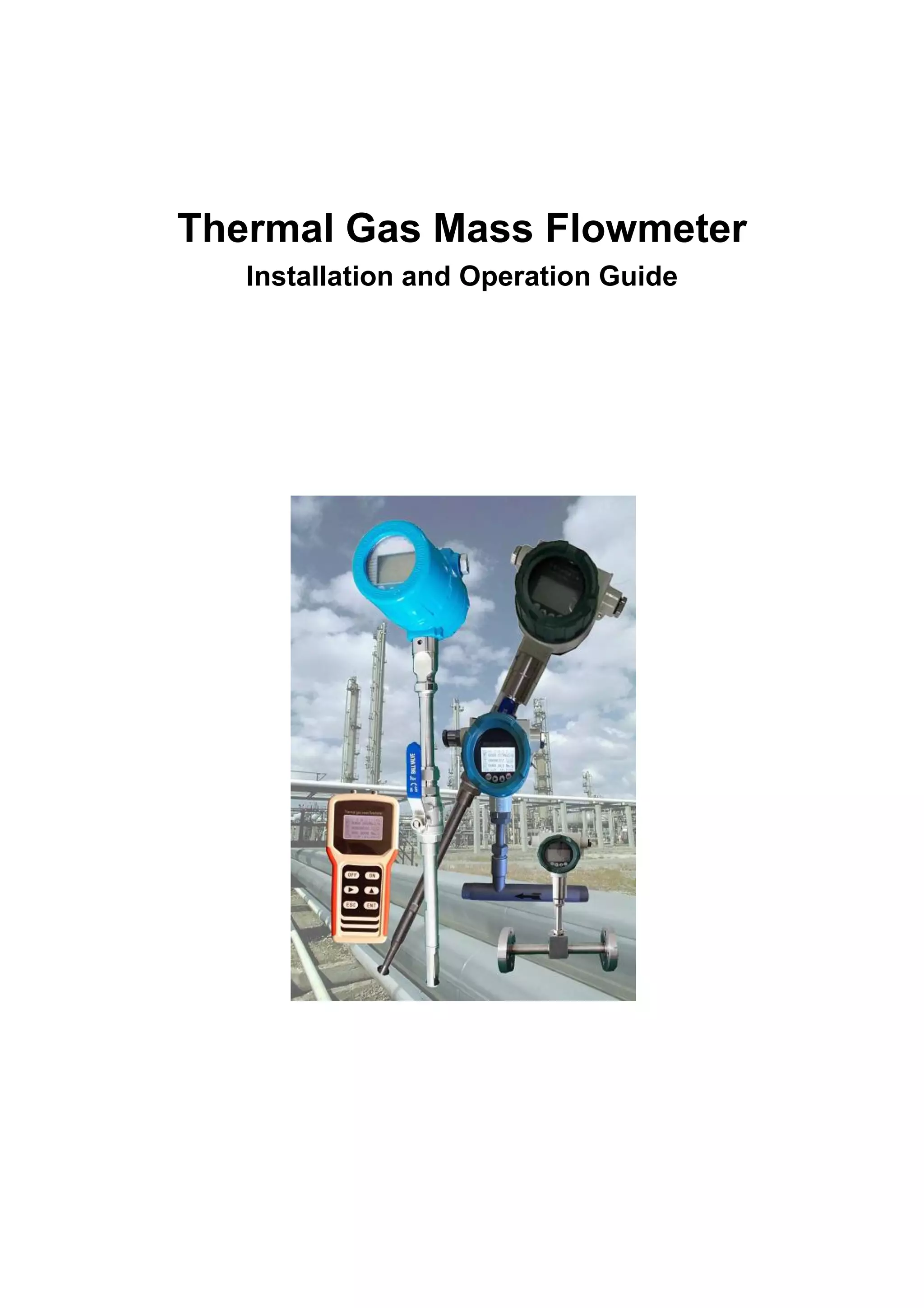
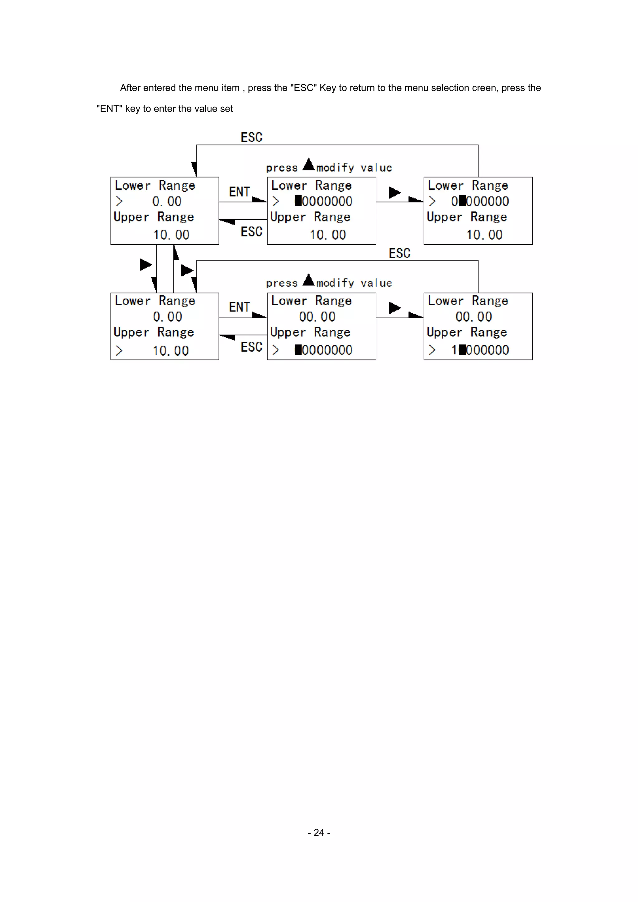
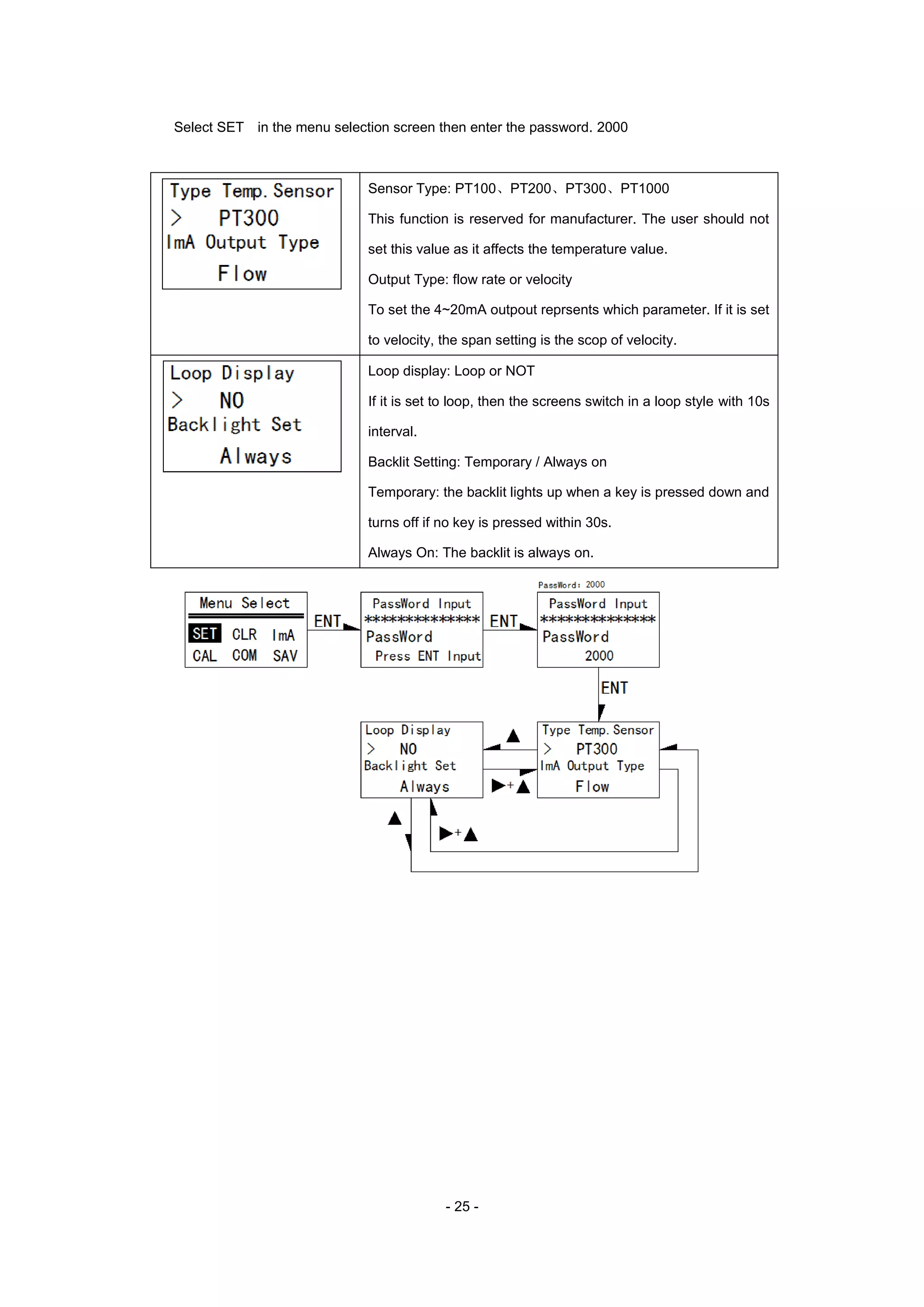
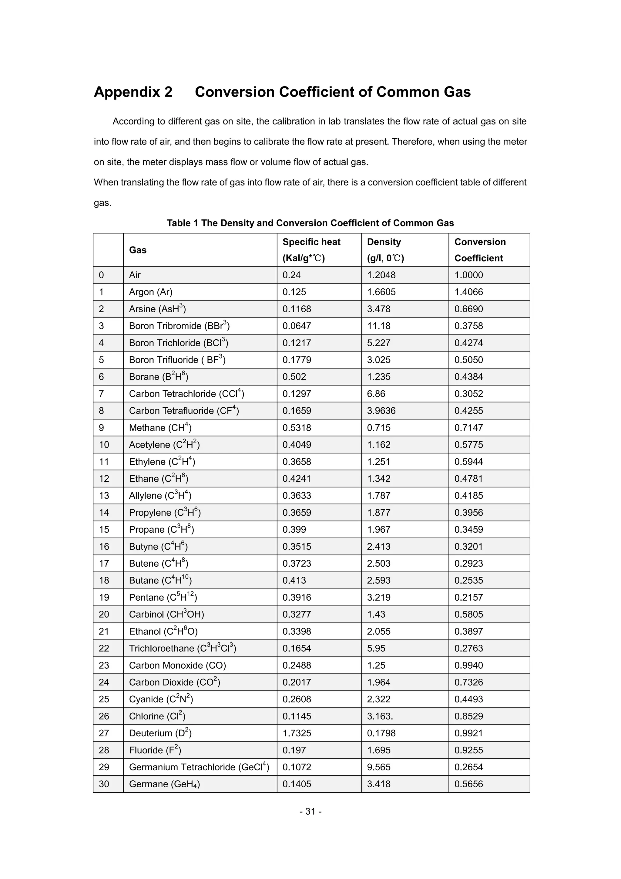
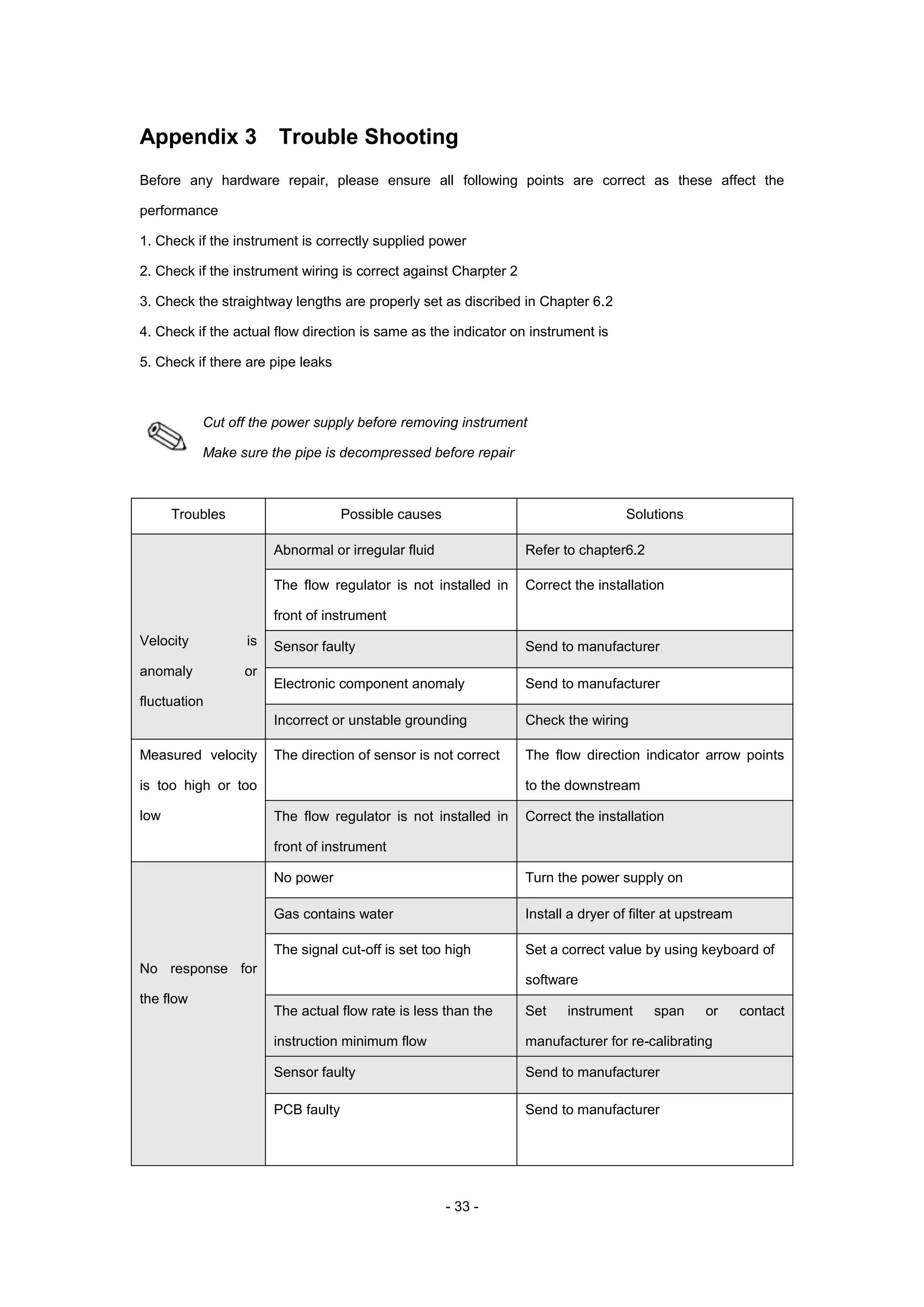
This document provides an installation and operation guide for a thermal gas mass flowmeter. It describes the measuring principle of using two temperature sensors, one heated, to monitor gas flow. Specifications include measuring various gases from 0.1-100 Nm/s with 1-2.5% accuracy from -40-220°C. Installation and wiring instructions are provided along with menus for the LCD display and appendices on conversions, troubleshooting and specifications.
El documento describe los procesos de fabricación y los productos ofrecidos por Beaucoup, una empresa ecuatoriana con más de 40 años de experiencia en la fabricación de productos metalmecánicos para aplicaciones eléctricas, electrónicas y de telecomunicaciones. La empresa tiene certificaciones ISO 9001:2015 y produce una variedad de gabinetes, cajas, racks y accesorios para el cableado estructurado siguiendo estrictos procesos de fabricación y control de calidad.
04-Introducción al analisis termográficoMiguel Pineda
Este documento presenta una introducción al análisis termográfico. Explica que la termografía infrarroja produce imágenes de la radiación infrarroja emitida por objetos para mostrar su condición térmica. Detalla las ventajas de los programas de análisis termográfico como reducciones en costos de mantenimiento y mejoras en seguridad. También describe cómo la capacidad de la termografía de realizarse de forma remota, bidimensional y en tiempo real la hace una herramienta útil, aunque tiene limitaciones como no poder penetrar pane
Termografia para diagnostico de edificios Eideo Análisis
Este documento proporciona información sobre FLIR Systems, el líder mundial en cámaras termográficas. Describe cómo funcionan las cámaras termográficas, las ventajas de la termografía, aplicaciones como inspecciones de edificios, y testimonios de clientes. También cubre las plantas de fabricación de FLIR, los mercados que sirve, y cómo seleccionar el fabricante adecuado de cámaras termográficas.
I. O documento lista as faixas de bitolas produzidas, bitolas padrão e tolerâncias de diversos produtos industriais da ArcelorMittal, incluindo barras laminadas, fio-máquina, perfis para serralheria e estruturais.
II. São detalhadas as normas de composição química ABNT/SAE J403, ABNT/SAE J404, SAE J1268 e DIN.
III. São apresentadas tabelas com propriedades mecânicas dos aços laminados e trefilados
This document describes the implementation of a bandgap reference circuit. It was designed by M. Lingadhar Reddy under the guidance of Mr. G. Shiva Kumar at GITAM University in Hyderabad, India from 2013-2015. The document outlines the basic operation of a bandgap reference circuit, which produces a reference voltage that is stable over changes in temperature, supply voltage, and process parameters. It discusses the tool and technology used, different approaches to bandgap references, and details the design and simulation results of a two-stage CMOS operational amplifier and final bandgap reference circuit implemented in a 90nm CMOS technology using Cadence Virtuoso.
Este documento descreve a quinta edição do livro "Juntas Industriais" de José Carlos Veiga. Contém informações sobre o autor, edições anteriores, gráfica, dados de catalogação e prefácio. O livro aborda temas como projeto, materiais, tipos e instalação de juntas industriais.
Series MSX and MSX Pro Magnesense® Differential Pressure TransmittersDwyer Instruments
The Series MSX and MSX Pro Magnesense® differential pressure transmitters are ideal for monitoring building control applications. With enhanced accuracy and stability, the MSX Pro is also suitable for high performance, critical environments.
To learn more or order, please visit https://info.dwyer-inst.com/msx-msxpro
Self-Regulating Heat Trace Cable Application and Operating PrinciplesIves Equipment
The document provides specifications and application information for Nelson Type CLT self-regulating heater cables. The cables consist of stranded copper conductors, a self-regulating conductive core, a thermoplastic elastomer jacket, and standard overjacket and metal braid. Tables are included that recommend cable wattages needed to maintain fluid temperatures in pipes of various sizes, insulation thicknesses, and ambient temperatures down to -40°F. The heaters are intended for freeze protection and temperature maintenance in pipelines and other fluid systems.
Este documento presenta el diseño e implementación de un sistema SCADA para controlar una planta piloto de producción y envasado de líquidos. El sistema SCADA consta de tres niveles: nivel de proceso, nivel de control y nivel de supervisión. El objetivo es reemplazar el sistema de control primitivo existente y aumentar la funcionalidad, especialmente en supervisión. Se revisará la instrumentación, se implementarán funciones de control en un PLC y reguladores, y se desarrollará una aplicación SCADA en Intouch para supervisión.
Este documento describe los requisitos y el proceso de instalación de WinCC flexible 2008 SP3. Explica los requisitos del sistema operativo, hardware y software necesarios, así como las opciones de instalación disponibles como instalación mínima, personalizada o completa. También cubre temas como la instalación de licencias, opciones y paquetes, y el tratamiento de errores. El objetivo es proporcionar una guía completa para la correcta instalación del software de ingeniería y tiempo de ejecución de WinCC flexible.
[Envimart's Products] Đồng hồ điện từ đo lưu lượng nước, MagFlux hãng MJKENVIMART
MagFlux flow meters use electromagnetic induction to measure flow of conductive liquids in closed pipes. They have no moving parts, provide accurate bidirectional measurement, and can be installed with the converter mounted on the sensor or remotely. Key features include large dynamic range, built-in data logging, pulse and analog outputs, and Modbus communication. They are available in sizes from DN15 to DN2000 with standard process connections.
This document is an instruction manual for the DELTA4000 12-kV Insulation Diagnostic System. It provides safety precautions for operating high voltage equipment and specifies the technical specifications, test modes, safety features, and accessories of the DELTA4000 system. The manual also details how to setup and use the system, including controls and connectors, the Delta Control user interface for running tests, and the PowerDB user interface for storing and analyzing test results.
This document discusses ultra thin body SOI FETs. Some key points:
- SOI uses a thin silicon layer on an insulating substrate to reduce parasitic capacitance and improve performance over bulk silicon. Fully depleted SOI is preferred for its thin size and reduced leakage/power consumption.
- Benefits of SOI include lower capacitance, resistance to latch-up, higher performance at lower voltages, reduced temperature effects, better yields, and reduced leakage currents.
- Ultra thin body SOI FETs have even better gate control and mobility due to thin channel thickness, lower parasitic capacitance, and reduced leakage currents, making them useful for applications like memory, microelectronics, RF devices,
1) O documento discute métodos de sintonia de controladores PID para sistemas de controle.
2) A síntese direta é um método que especifica a saída desejada do sistema para obter o controlador PID correspondente.
3) Quando a saída desejada possui a forma de uma resposta de 1a ordem sem atraso, é possível projetar o controlador PID para fornecer essa resposta com um tempo de estabilização de aproximadamente 4 vezes o constante de tempo desejado.
Signal and power integrity challenges in VLSI circuits and strategies for the...Pushpak Dagade
This document provides an overview of signal and power integrity challenges in VLSI circuits. It discusses interconnect modeling and the impacts of interconnect on delay, crosstalk, and power. Crosstalk effects and mitigation techniques are described. Supply bounce issues caused by di/dt noise are examined, including causes and effects. Mitigation approaches for supply bounce like intelligent engineering, guard rings, and on-chip decoupling capacitors are covered. The document concludes with a section on electromagnetic emission and interference in VLSI circuits and techniques to reduce emissions and noise.
1. O documento apresenta um curso de formação de operadores de refinaria sobre termodinâmica.
2. O curso aborda conceitos fundamentais da termodinâmica como pressão, estado, processo e equilíbrio de sistemas termodinâmicos.
3. Também são apresentados tópicos como as leis da termodinâmica, máquinas térmicas, ciclos térmicos, aplicações em sistemas térmicos e exercícios.
Este documento proporciona información técnica detallada sobre los compresores semiherméticos 06D/E de Carlyle, incluyendo sus características, especificaciones, diagramas, consideraciones de diseño de sistemas y accesorios. Explica el significado de los números de modelo de los compresores y proporciona tablas con sus especificaciones eléctricas y de capacidad. Además, describe los componentes y sistemas clave de los compresores, como las válvulas, pistones, bomba de aceite y control de
ABB are a leading manufacturer of medium voltage (MV) fuses used as main or back up protection elements of systems and apparatus. Fuses (commonly recognized as High Voltage Fuses) are classified as current limiting and non-current limiting (expulsion).
ABB fuses are designed based on wide application experience coming from designing of electrical protection in medium voltage systems and coordination with ABB products where fuses are applicable (air and SF6 insulated switchgears with load break switches, distribution transformers and contactors).
ABB MV HV medium-high voltage fuses protect distribution transformers, motors, switchgear and capacitor banks against overload currents - ABB MV-HV fuses can operate as sole devices or can be combined with air/SF6 insulated switch disconnectors. T&D distribute ABB medium voltage fuses for safe protection of 3.3kV, 6.6kV, 7.2kV, 11kV, 12kV 15kV, 20kV, 22kV, 24kV, 33kV, 36kV and 42kV cable systems.
Este documento fornece uma introdução sobre instrumentação industrial, sensores e transdutores. Apresenta definições fundamentais de sensor, transdutor, sensores discretos e absolutos. Também descreve conceitos como sensibilidade, exatidão, precisão, linearidade, estabilidade, alcance e resolução. Por fim, inclui exemplos de medição de pressão, vazão, nível, força, posição, temperatura e sensores de presença.
Este documento presenta las normas y especificaciones para proyectos de instalaciones de aire acondicionado en México. Incluye información sobre temperaturas exteriores e interiores de diseño, humedad relativa, velocidad del aire, ruido permitido, cálculo de capacidad, selección de sistemas y materiales para ductos. Además, presenta tablas con datos climáticos normalizados para diferentes ciudades mexicanas que son útiles para el diseño de sistemas de aire acondicionado.
Este documento presenta un tutorial sobre el análisis de transitorios electromagnéticos utilizando el software DigSILENT PowerFactory. Se dividen los temas en 5 secciones: 1) Corriente de arranque de transformadores, 2) Transitorios de maniobra en capacitores, 3) Tensión de recuperación tras despeje de fallas, 4) Transitorios de energización de líneas, y 5) Sobretensiones de origen atmosférico. Cada sección contiene ejemplos paso a paso para simular diferentes escenarios transitor
1. Fully Depleted Silicon On Insulator (FD-SOI) is an innovation that uses an ultra-thin silicon film and buried oxide layer to improve transistor performance and reduce leakage currents.
2. By using a thin buried oxide and silicon film, FD-SOI allows the depletion region to cover the entire film, improving electrostatic characteristics and reducing parasitic capacitance compared to bulk transistors.
3. The improvements allow FD-SOI transistors to operate faster at lower voltages while significantly reducing leakage currents and improving power efficiency through improved body biasing controls.
The document provides an operation manual for a DMF-1 Series Coriolis mass flow meter. It discusses safety guidelines, an overview of the instrument's operation, technical parameters, structure diagrams, terminal wiring, installation instructions, calibration procedures, dimensions, troubleshooting tips, gas density conversions, and upper flow limits.
Hướng dẫn sử dụng Teso 570
https://testostore.vn/san-pham/may-do-chan-khong-testo-570/
https://testostore.vn/danh-muc/do-ap-suat/may-do-ap-suat-chan-khong/
This document describes the SHTW2 humidity and temperature sensor IC. It provides specifications for the sensor including accuracy tolerances for humidity and temperature measurements, electrical characteristics, and timing information. Key features of the SHTW2 include an ultra-small flip chip package, industry-proven reliability, and typical accuracy of ±3% RH and ±0.4°C. The sensor uses Sensirion's CMOSens technology to integrate a humidity sensor, temperature sensor, analog and digital signal processing, calibration memory, and I2C interface on a single chip.
Hướng dẫn sử dụng máy đo đa năng Testo 550 KIT
https://testostore.vn/san-pham/testo-550-kit/
https://testostore.vn/danh-muc/do-ap-suat/may-do-ap-suat-chan-khong/
The document compares Thermal Stream Systems and Direct Thermal Head systems for temperature testing of integrated circuits (ICs). Thermal Stream Systems use compressed air to control temperature but require more space, infrastructure, and maintenance. Direct Thermal Head systems provide temperature control through direct contact and are more portable, quieter to operate, easier to set up, and less expensive to purchase and maintain long-term. For many IC testing needs, Direct Thermal Head systems offer a more practical solution due to their compact size, plug-and-play capability, and overall lower cost of ownership.
This document provides an overview of the AMS2750E heat treatment standard. It is part of a series of guides on heat treatment control. This specific guide focuses on explaining key aspects of the AMS2750E standard for suppliers and end users, including instrumentation requirements, system accuracy tests, temperature uniformity surveys, and equipment classes. The guide also discusses how instrument suppliers can help meet the standard's requirements through services like calibrated thermocouples, instruments, field testing equipment, calibration, training and data management support.
Thermal power stations require extensive instrumentation to monitor complex processes and ensure stable power generation. Instrumentation provides critical information to operators for starting up and shutting down processes safely. It also helps maintain the balance between heat input and electricity output by measuring deviations and enabling automatic controls and protections. The cost of instrumentation is high, around 7-12% of total costs, due to larger unit sizes, modernized equipment, and improved operator awareness of instrumentation benefits.
Vikalo Instruments is leading manufacturing company to provide Process Engineering Solutions with our industrial products such as Pressure & Temperature Gauges,Thermocouple,Rtd,Industrial Heater and other process equipment in the Instrumentation Engineering filed.
This document discusses automation in the pharmaceutical industry. It defines automation and describes its advantages such as improved quality, reduced costs, and increased safety. Automation can occur at various stages of manufacturing like material handling, production processes, and quality control. The document also discusses process control and variables like temperature, pressure, and flow that are important to measure. It provides examples of automation in tablet manufacturing that can improve material handling and specific unit operations.
Hướng dẫn sử dụng Testo 420
https://testostore.vn/san-pham/may-do-ap-suat-chenh-lech-testo-420-0560-0420/
https://testostore.vn/danh-muc/do-ap-suat/may-do-ap-suat-vi-sai/
Transformer monitoring and controlling with GSM based systemIRJET Journal
This document describes a proposed system for monitoring and controlling a distribution transformer using GSM technology. The system would monitor key parameters like voltage, current, temperature, oil level and detect any issues. Sensors would collect this data and send it to an Arduino controller. The controller would analyze the data and if any problems were detected, it would send an alert message using a GSM modem to notify operators remotely. This system aims to monitor transformers in real-time to detect issues early and prevent failures, allowing for more efficient maintenance and reducing costs. It could provide parameter updates at regular intervals to a control station for monitoring transformer health remotely.
What is a flowmeter ?
Simply a device that can monitor and measure the actual amount of ‘product’ being sent through it. Typically flowmeters in industry are used for monitoring use of water, chemicals, ingredients, etc.
Srinivas Reyya is seeking a challenging position utilizing his 11 years of experience in industrial instrumentation. He has worked in the sugar and cement industries calibrating and maintaining field instruments. He holds qualifications in instrumentation, electricity, and apprenticeships. Reyya has skills in software, operating systems, and hardware troubleshooting. He provides details of his professional experience maintaining and calibrating various instruments at multiple companies in the sugar and cement industries.
This document describes the design and installation of a low-cost wind monitoring system using scrap and readily available materials. It consists of a 4-cup anemometer to measure wind speed, a lightweight wind vane to measure wind direction, and a platinum resistance temperature detector to measure ambient air temperature. The system provides accurate measurements at a fraction of the cost of a commercial system. It was calibrated and tested and found to perform reliably while significantly reducing costs for small industries.
Thermal dispersion mass flow transmitters measure mass flow by detecting heat dissipation from a heated surface. The sensor contains two mass balanced elements with precision matched RTDs. The reference sensor measures the process temperature (up to +400° F [+200° C]); the second RTD measures the temperature of the heated sensor. The power to the heater is varied to maintain a constant temperature difference above the reference temperature.
There is an inherent non-linear relationship between power and mass flow. A microprocessor compares the power against the calibration curve and converts the power requirements to the mass flow rate. Temperature is also measured to provide temperature compensation of the mass flow over the operating range of the instrument.
Similar to Thermal mass flow meter English manual (20)
In the field of industrial measurement and control, radar level meters are widely favored for their advantages of high accuracy and non-contact measurement. However, as a key component of this system – antenna, its performance directly affects the measurement effect of the whole level meter. Today, we will explore the knowledge of radar level meter antenna in depth, in order to better understand its working principle and application.
In the process of modern urban wastewater treatment, the fecal liquid receiving tank undertakes the task of collecting feces and organic waste in domestic sewage, which is an indispensable link in the wastewater treatment chain, and the special environmental conditions of the fecal liquid receiving tank bring challenges to the liquid level measurement.
In this paper, we will discuss the characteristics of fecal liquid receiving tank and analyze the application effect of radar level meter in liquid level monitoring through practical cases.
In the bakery industry, the management of ingredients is crucial. Accurately monitoring the stock level of bakery ingredients in small silos is of great significance to ensure production continuity and reduce waste.
In this paper, we will discuss the level characteristics of small silos for bakery ingredients, and combine them with an actual measurement case to illustrate the application effect of radar level meters.
Industrial measurement and control technology, radar level meter has become an indispensable tool for many industries with its advantages of high accuracy, high reliability and easy maintenance.
However, there are many brands of radar level meters on the market with different functions, how to make a wise choice among the complicated products? This article will provide you with a detailed brand selection guide to help you find the most suitable radar level meter for your needs.
In ship operation, ensuring accurate monitoring of fuel level in fuel tanks is extremely critical for safe navigation and energy efficiency management. Accurate measurement of fuel tank oil level can guarantee the stable oil supply of ship power system, and at the same time avoid oil spill accident and protect the marine environment.
Therefore, the choice of measurement technology for fuel tank oil level on ships is particularly important, and guided wave radar level meter is highly respected in this field for its high precision and high reliability.
In the process of industrial production, especially in the fields of petrochemical industry and mining industry, the sulfur pit is used as a facility for storing liquid sulfur, and the accurate measurement of its liquid level is of vital significance for guaranteeing production safety and environmental protection.
The characteristics of liquid sulfur in the sulfur pit and the environmental conditions put forward special requirements for the liquid level measurement technology, and the radar level meter, with its high accuracy and high reliability, shows a unique advantage in this field.
As an important base for energy conversion and supply, the operational efficiency and safety of power plants are of paramount importance. In the daily operation of power plants, level monitoring is a key link to ensure smooth production processes and prevent accidents.
As an advanced level measurement device, radar level meter is widely used in power plants because of its high accuracy, high reliability and adaptability. In this paper, we will discuss how to select and apply radar level meter in power plants.
In the petrochemical industry, the Amine Absorption Tower plays a vital role. It removes harmful carbon dioxide and other acid gases from industrial emissions by chemical absorption. The high viscosity and corrosive nature of the amine liquid makes monitoring and controlling the level of the amine liquid absorption tower particularly complex.
Therefore, the selection of a level measurement technology that is both accurate and reliable is essential to ensure the efficient operation of amine absorption towers. In this context, guided wave radar level meter is favored for its excellent performance.
In the field of industrial measurement, radar level meters are favored because of their high accuracy, reliability and wide range of applications. However, there are a wide variety of radar level meters on the market, and how to judge their quality has become a problem that users must face. Next, we will discuss the evaluation criteria of radar level meters from multiple dimensions.
First of all, accuracy is the primary indicator for measuring the performance of radar level meters. A high-quality radar level meter should have high-precision measurement capabilities and a very small error range. Therefore, when choosing, you should carefully check the product’s technical specifications to understand its accuracy parameters. Secondly, stability is also the key to judging the quality of radar level meters. In harsh industrial environments, external factors such as temperature, pressure, humidity, etc. may affect the stability of the equipment. High-quality radar level meters can maintain stable operation under a wide range of environmental conditions, such as operating normally in the temperature range of -40°C to +250°C, and are not easily affected by high pressure or steam. Furthermore, adaptability is a criterion that cannot be ignored when evaluating radar level meters. Excellent radar level meters can adapt to different media, including solids, liquids, slurries, etc.
In modern industrial and environmental protection projects, leachate wells are key facilities for treating wastewater produced in landfills. Accurate measurement of their liquid levels is of great significance for ensuring environmental safety and improving treatment efficiency.
Just as doctors use stethoscopes to accurately capture the rhythm of a heartbeat, engineers rely on radar level gauges to gain insight into changes in fluid levels in leachate wells. This article will conduct an in-depth analysis of the liquid level characteristics of leachate wells, and demonstrate the application value of radar level meters in this field through an actual measurement case.
Level measurement in cullet silos is a challenging task in industrial production. Due to the characteristics of cullet, such as irregular shape, fragility and reflectivity, it is not easy to accurately measure its material level in actual measurements.
This article will introduce the material level characteristics of cullet silos in detail, and analyze the application of radar level meters in cullet silo material level measurement based on actual cases.
The characteristics of the material level of the cullet silo mainly include the following aspects: Irregular material shape: The cullet shows an irregular shape, which causes the density and volume of the material accumulation to change greatly, making it difficult to measure the material level.
Materials with strong reflectivity: Broken glass has strong reflectivity and strong absorption and scattering effects on radar waves, which may cause severe attenuation of measurement signals and affect measurement accuracy. Poor material fluidity: Broken glass is easily stuck between pieces, resulting in poor fluidity and affecting the normal flow and emptying of materials.
Harsh measurement environment: Crushed glass silos are usually located in harsh environments such as high temperature, high humidity, and dust, which place high requirements on the durability and stability of measurement equipment.
As a non-contact measuring instrument, radar level gauge is widely used in liquid level measurement of various liquid storage tanks. However, during the actual installation process, some common misunderstandings may affect its measurement accuracy and stability. This article will discuss the installation misunderstandings of radar level gauges to help users better understand and avoid these problems.
The main building of a hydropower station is the core area of the hydropower station, where the measurement and control of liquid level are crucial to the stable operation of the hydropower station.
There are many instruments on the market that can be used to measure the liquid level in the main building of a hydropower station.
Radar level meter is one of them. It has been widely used in the liquid level measurement of the main building of a hydropower station.
Today we will introduce the application of radar level gauges in liquid level measurement in the main building of hydropower stations through two actual measurement cases.
In the ethanol production process, raw material silos are important facilities for storing raw materials for ethanol production, and accurate measurement of their material levels is of great significance to ensure production efficiency and product quality. As a high-precision measuring instrument, radar level meter is widely used in material level measurement in raw material silos of ethanol production.
This article will introduce the characteristics of ethanol production silos, and use a practical case to illustrate the application of radar level meters in the material level measurement of ethanol production raw material silos.
As a non-contact measuring instrument, radar level gauge has the characteristics of high measurement accuracy, good stability, and small impact on the measured medium. It is widely used in the measurement of various liquid levels.
However, in practical applications, radar level gauge distortion sometimes occurs, which brings great trouble to the measurement work. This article will introduce the causes and treatment methods of radar level gauge distortion.
It is common in industry to measure various non-electrical physical quantities, such as temperature, pressure, speed, angle, etc., which need to be converted into analog electrical signals before they can be transmitted to a control room or display device hundreds of meters away.
This device that converts physical quantities into electrical signals is called a transmitter. The most widely used in industry is to use 4~20mA current to transmit analog quantities.
As a non-contact measuring instrument, radar level gauge has been widely used in industrial applications. However, in actual use, radar level gauges may be affected by various interference factors, resulting in inaccurate measurement results.
In order to ensure the measurement accuracy and stability of the radar level gauge, eliminating interference has become a problem that must be faced.
As a renewable energy source, the liquid level measurement of biogas digesters has been put to the test. As we all know, in the industrial field, the application of radar level gauges is becoming more and more common.
So, can the radar level meter be used to measure small biogas pools? This article will discuss the principle, measurement range, error analysis and other aspects of the radar level meter.
In the ever-evolving landscape of industrial instrumentation, Coriolis mass flow meters have emerged as pivotal devices, revolutionizing the measurement and control of fluid flows across various sectors. As global industries strive for enhanced accuracy, efficiency, and sustainability, the demand for advanced flow measurement technologies has surged. Coriolis mass flow meters, with their ability to provide precise and real-time measurements of mass flow, density, and temperature, have become indispensable tools in optimizing processes and ensuring compliance with rigorous industry standards.
This article delves into the dynamic and rapidly evolving global market trends surrounding Coriolis mass flow meter technology. From oil and gas to pharmaceuticals, food and beverage to chemicals, the application of Coriolis meters spans diverse sectors, underscoring their versatility. With ongoing technological advancements pushing the boundaries of precision and reliability, stakeholders in these industries are progressively incorporating Coriolis mass flow meters into their operations. This integration fosters innovation and propels the next phase of industrial evolution.
Radar level meter, as an advanced measuring equipment, has been widely used in many industries due to its high accuracy and high stability. Especially in the key field of offshore oil and gas exploration, the role of radar level gauges is even more indispensable. This article will discuss the application value of radar level meters in the offshore oil and gas exploration industry.
More from Dalian Zero Instrument Technology Co., Ltd China (20)
IMPACT Silver is a pure silver zinc producer with over $260 million in revenue since 2008 and a large 100% owned 210km Mexico land package - 2024 catalysts includes new 14% grade zinc Plomosas mine and 20,000m of fully funded exploration drilling.
Unveiling the Dynamic Personalities, Key Dates, and Horoscope Insights: Gemin...my Pandit
Explore the fascinating world of the Gemini Zodiac Sign. Discover the unique personality traits, key dates, and horoscope insights of Gemini individuals. Learn how their sociable, communicative nature and boundless curiosity make them the dynamic explorers of the zodiac. Dive into the duality of the Gemini sign and understand their intellectual and adventurous spirit.
Starting a business is like embarking on an unpredictable adventure. It’s a journey filled with highs and lows, victories and defeats. But what if I told you that those setbacks and failures could be the very stepping stones that lead you to fortune? Let’s explore how resilience, adaptability, and strategic thinking can transform adversity into opportunity.
The Most Inspiring Entrepreneurs to Follow in 2024.pdfthesiliconleaders
In a world where the potential of youth innovation remains vastly untouched, there emerges a guiding light in the form of Norm Goldstein, the Founder and CEO of EduNetwork Partners. His dedication to this cause has earned him recognition as a Congressional Leadership Award recipient.
[To download this presentation, visit:
https://www.oeconsulting.com.sg/training-presentations]
This PowerPoint compilation offers a comprehensive overview of 20 leading innovation management frameworks and methodologies, selected for their broad applicability across various industries and organizational contexts. These frameworks are valuable resources for a wide range of users, including business professionals, educators, and consultants.
Each framework is presented with visually engaging diagrams and templates, ensuring the content is both informative and appealing. While this compilation is thorough, please note that the slides are intended as supplementary resources and may not be sufficient for standalone instructional purposes.
This compilation is ideal for anyone looking to enhance their understanding of innovation management and drive meaningful change within their organization. Whether you aim to improve product development processes, enhance customer experiences, or drive digital transformation, these frameworks offer valuable insights and tools to help you achieve your goals.
INCLUDED FRAMEWORKS/MODELS:
1. Stanford’s Design Thinking
2. IDEO’s Human-Centered Design
3. Strategyzer’s Business Model Innovation
4. Lean Startup Methodology
5. Agile Innovation Framework
6. Doblin’s Ten Types of Innovation
7. McKinsey’s Three Horizons of Growth
8. Customer Journey Map
9. Christensen’s Disruptive Innovation Theory
10. Blue Ocean Strategy
11. Strategyn’s Jobs-To-Be-Done (JTBD) Framework with Job Map
12. Design Sprint Framework
13. The Double Diamond
14. Lean Six Sigma DMAIC
15. TRIZ Problem-Solving Framework
16. Edward de Bono’s Six Thinking Hats
17. Stage-Gate Model
18. Toyota’s Six Steps of Kaizen
19. Microsoft’s Digital Transformation Framework
20. Design for Six Sigma (DFSS)
To download this presentation, visit:
https://www.oeconsulting.com.sg/training-presentations
Brian Fitzsimmons on the Business Strategy and Content Flywheel of Barstool S...Neil Horowitz
On episode 272 of the Digital and Social Media Sports Podcast, Neil chatted with Brian Fitzsimmons, Director of Licensing and Business Development for Barstool Sports.
What follows is a collection of snippets from the podcast. To hear the full interview and more, check out the podcast on all podcast platforms and at www.dsmsports.net
SATTA MATKA SATTA FAST RESULT KALYAN TOP MATKA RESULT KALYAN SATTA MATKA FAST RESULT MILAN RATAN RAJDHANI MAIN BAZAR MATKA FAST TIPS RESULT MATKA CHART JODI CHART PANEL CHART FREE FIX GAME SATTAMATKA ! MATKA MOBI SATTA 143 spboss.in TOP NO1 RESULT FULL RATE MATKA ONLINE GAME PLAY BY APP SPBOSS
Storytelling is an incredibly valuable tool to share data and information. To get the most impact from stories there are a number of key ingredients. These are based on science and human nature. Using these elements in a story you can deliver information impactfully, ensure action and drive change.
[To download this presentation, visit:
https://www.oeconsulting.com.sg/training-presentations]
This presentation is a curated compilation of PowerPoint diagrams and templates designed to illustrate 20 different digital transformation frameworks and models. These frameworks are based on recent industry trends and best practices, ensuring that the content remains relevant and up-to-date.
Key highlights include Microsoft's Digital Transformation Framework, which focuses on driving innovation and efficiency, and McKinsey's Ten Guiding Principles, which provide strategic insights for successful digital transformation. Additionally, Forrester's framework emphasizes enhancing customer experiences and modernizing IT infrastructure, while IDC's MaturityScape helps assess and develop organizational digital maturity. MIT's framework explores cutting-edge strategies for achieving digital success.
These materials are perfect for enhancing your business or classroom presentations, offering visual aids to supplement your insights. Please note that while comprehensive, these slides are intended as supplementary resources and may not be complete for standalone instructional purposes.
Frameworks/Models included:
Microsoft’s Digital Transformation Framework
McKinsey’s Ten Guiding Principles of Digital Transformation
Forrester’s Digital Transformation Framework
IDC’s Digital Transformation MaturityScape
MIT’s Digital Transformation Framework
Gartner’s Digital Transformation Framework
Accenture’s Digital Strategy & Enterprise Frameworks
Deloitte’s Digital Industrial Transformation Framework
Capgemini’s Digital Transformation Framework
PwC’s Digital Transformation Framework
Cisco’s Digital Transformation Framework
Cognizant’s Digital Transformation Framework
DXC Technology’s Digital Transformation Framework
The BCG Strategy Palette
McKinsey’s Digital Transformation Framework
Digital Transformation Compass
Four Levels of Digital Maturity
Design Thinking Framework
Business Model Canvas
Customer Journey Map
Best Competitive Marble Pricing in Dubai - ☎ 9928909666Stone Art Hub
Stone Art Hub offers the best competitive Marble Pricing in Dubai, ensuring affordability without compromising quality. With a wide range of exquisite marble options to choose from, you can enhance your spaces with elegance and sophistication. For inquiries or orders, contact us at ☎ 9928909666. Experience luxury at unbeatable prices.
Ellen Burstyn: From Detroit Dreamer to Hollywood Legend | CIO Women MagazineCIOWomenMagazine
In this article, we will dive into the extraordinary life of Ellen Burstyn, where the curtains rise on a story that's far more attractive than any script.
Presentation by Herman Kienhuis (Curiosity VC) on Investing in AI for ABS Alu...Herman Kienhuis
Presentation by Herman Kienhuis (Curiosity VC) on developments in AI, the venture capital investment landscape and Curiosity VC's approach to investing, at the alumni event of Amsterdam Business School (University of Amsterdam) on June 13, 2024 in Amsterdam.
Dive into this presentation and learn about the ways in which you can buy an engagement ring. This guide will help you choose the perfect engagement rings for women.
3. - 3 -
1. About this manual
Thank you for choosing our products.
Through this manual, we strive to give you an accurate understanding of the thermal mass
flowmeter measurement principle, related concepts, terminology and installation and application of the
correct methods and conditions.
Symbols and meanings used in this manual:
Graphic symbol meanings in this manual
Incorrect operation or infringement with the relevant regulations and the instructions
of this manual may result in damage of the instrument and equipment
Important concepts, definitions or methods
Caution!
Improper or careless operation and application may result in incorrect operation or
even damage to the instrument
Grounding mark
The Specifications and requirements for using intrinsical safety instruments
4. - 4 -
2. Safety Information
2.1 Use personnel
The thermal mass flowmeter is a precision instrument which is produced by the latest technology
and technology. Improper installation and use can lead to abnormal and damage of the instrument
and even the process control equipment. Engineers and technicians who install, set up and
connect the product must read this manual carefully before using the instrument.
2.2 store and handling
·Storage temperature:-40℃~80℃
·Relative humidity:20~90%
The storage and handling process should be placed in the instrument box to avoid bumping or
shock.
2.3 Application condition
Before installation should be sure that the measured medium temperature and pressure is not
more than the nominal temperature and pressure. Determine whether the measured gas is
pure, the gas does not contain particulate matter, so as to avoid the damage of granular
materials on the sensor.
2.4 Safety standards and specifications
Installation, wiring and use of this product should comply with the requirements specified in this
manual and the general international safety standards, accident prevention measures and local
standards.
2.5 Intrinsic safety and explosion protection
Dangerous places or may be flammable gas and air mixture should use explosion-proof
type thermal mass flowmeter in - field measurement;
he explosion-proof thermal mass flowmeter with appropriate safety gate shall be
obtained using supporting explosion-proof certification;
Installation and wiring - intrinsic safety instrument system and related equipment shall
comply with the relevant standards and norms of the country.
2.6 Environmental protection
The packaging of this product can meet the ISO:14001 specification, and will not pollute the
environment.
Please return to the professional recycling company or send back to us, so as to avoid polluting the
environment.
5. - 5 -
3. Introduction
3.1 measuring principle
Thermal gas mass flow meter is designed on the basis of thermal dispersion, and adopts method of
constant differential temperature to measuring gas flow. It has advantages of small size, easy installation,
high reliability and high accuracy, etc.
The meter contains two platinum resistance temperature sensors. The thermal principle operates by
monitoring the cooling effect of a gas stream as it passes over a heated sensor. Gas flowing through the
sensing section passes over two sensors one of which is used conventionally as a temperature sensor,
whilst the other is used as a heater. The temperature sensor monitors the actual process values whilst
the heater is maintained at a constant differential temperature above this by varying the power consumed
by the sensor. The greater the gas velocity, the greater the cooling effect and power required to maintain
the differential temperature. The measured heater power is therefore a measure of the gas mass flow
rate.
The format of gas velocity and power is shown as below:
……(1)
Where: is specific gravity of medium
V is velocity
K is balance coefficient
Q is heater power
Δ T is differential temperature
The medium temperature range of meter is -40℃~220℃.
In the format (1), the specific gravity of medium is related to the density:
……(2)
Where: is the medium density in working condition(kg/m
3
)
ρn is the medium density in standard condition, 101.325kPa and 20℃ (kg/m
3
)
P is the pressure in working condition(kPa)
T is the temperature in working condition (℃)
In the formats (1) and (2), there is a certain functional relationship between the velocity and pressure in
working condition, medium density, the temperature in working condition.
Due to the sensor temperature is always 30℃ higher than the medium temperature (environment
temperature), and the meter adopts method of constant differential temperature, therefore the meter do
not need to do temperature and pressure compensation in principle.
6. - 6 -
3.2 Specifications
Features
Measuring the mass flow or volume flow of gas
Do not need to do temperature and pressure compensation in principle with accurate measurement
and easy operation.
Wide range: 0.5Nm/s~100Nm/s for gas. The meter also can be used for gas leak detection
Good vibration resistance and long service life. No moving parts and pressure sensor in transducer,
no vibration influence on the measurement accuracy.
Easy installation and maintenance. If the conditions on site are permissible, the meter can achieve
a hot-tapped installation and maintenance. (Special order of custom-made)
Digital design, high accuracy and stability
Configuring with RS485 or HART interface to realize factory automation and integration
Description Specifications
Measuring Medium Various gases (Except the acetylene)
Pipe Size DN10~DN4000mm
Velocity 0.1~100 Nm/s
Accuracy ±1~2.5%
Working Temperature
Sensor: -40℃~+220℃
Transmitter: -20℃~+45℃
Working Pressure
Insertion Sensor: medium pressure≤ 1.6MPa
Flanged Sensor: medium pressure≤ 1.6MPa
Special pressure please contact us
Power Supply 24VDC or 220VAC
Response Time 1s
Output
4-20mA (optoelectronic isolation, maximum load 500Ω), Pulse, RS485
(optoelectronic isolation) and HART
Alarm Output 2 line Relay, Normally Open state, 3A/30V/DC
Sensor Type Standard Insertion, Hot-tapped Insertion and Flanged
Construction Compact and Remote
Pipe Material Carbon steel, stainless steel, plastic, etc
Display
4 lines LCD
Mass flow, Volume flow in standard condition, Flow totalizer, Velocity, etc.
Protection Class IP65
Sensor Housing
Material
Stainless steel (316)
7. - 7 -
3.3 Mechanical Construction
3.3.1 Appearance
Fig. 1 Standard Insertion Flow Meter Fig. 2 Flanged Flow Meter
(Pipe size DN100-DN500) (Pipe size DN10-DN80)
Fig. 3 Hot-tapped Insertion Flow Meter
(Pipe size DN100-DN4000. Special requirements please contact us)
The insertion sensor of compact insertion flow meter should be inserted to axis of pipe, and the length of
the insertion sensor is decided by pipe size, please confirm the pipe size when ordering. If the insertion
sensor can’t be inserted to axis of pipe, the manufacturer will provide a calibration factor to achieve an
accurate measurement.
8. - 8 -
3.3.2 Dimensions
Dimensions of standard insertion sensor Dimensions of hot-tapped insertion sensor
The dimensions of flanged sensor
PN1.6Mpa Plane and surface plate flat welding steel pipe flanges (Unit: mm)
Nominal
Diameter
Flange
Outer
diameter
Center
Hole
Screw
Hole
Screw
Thread
Sealing Face
Flange
Thickness
Pipeline
Length
DN D k n×L d f C L
15 95 65 4×14 M12 46 2 14 160
20 105 75 4×14 M12 56 2 16 1600
25 115 85 4×14 M12 65 2 16 200
32 140 100 4×18 M16 76 2 18 200
40 150 110 4×18 M16 84 2 18 200
50 165 125 4×18 M16 99 2 20 200
65 185 145 4×18 M16 118 2 20 200
80 200 160 8×18 M16 132 2 20 200
100 220 180 8×18 M16 156 2 22 200
For DN15-DN80, the meter can be made with threading to connect.
The above table is used for rated pressure of 1.6MPa. If the rated pressure is more than 1.6MPa, please
contact us for special order.
9. - 9 -
4. Wiring
4.1 Preparation of wiring
You should read and connection method of supporting the use of thermal mass flowmeter
or other unit instrument system and requires careful - before connection;
The external cable recommended two core shielded cable and cable connection and
good sealing;
The explosion-proof products should be selected in accordance with the relevant
standard of BenAn instrument cable and make sure that the cable parameters meet the
explosion-proof instrument system requirements;
Working voltage range of DC18~30V. When the voltage is higher than DC30V, the
instrument will be damaged, and measures should be taken to prevent the supply voltage
from above 30V;
To the 24V DC power supply thermal mass flowmeter shall meet the requirements of
IEC-1010-1 or equivalent standard SELV safety extra low voltage;
Before the connection with the voltmeter to measure the power supply voltage, the
voltage is DC24V;
10. - 10 -
4.2 Terminal description
Terminal diagram Mark Description
24V+ 24V Power supply positive pole
24V- 24V Power supply 0V
OUT24
V
24V Power output
GND RS232 GND
TXD RS232 TXD
RXD RS232 RXD
P+ Pulse output positive pole
P- Pulse output negative pole
I+ Current output positive pole
I- Current output negative pole
485+/A RS485 communication interface A
485-/B RS485 communication interface B
ALARM
1
Alarm output 1
ALARM
2
Alarm output 2
P-LED Power indicator
I-LED Analog output indicator
Mounting hole of circuit board and shell
Mounting hole between boards and
boards
Sensor terminal
PT20/PT300 is
Default combination ,
Other optional sensors
PT20/PT200、 PT20/PT1000、
12. - 12 -
5. technical parameters
Power Supply Supply Voltage 24VDC/1.5A
Allow residual ripple:0~100Hz,
Upp = 30Mv,Uss<10mV
Maximum noise:500Hz~10KHz ,Ueff = 2.0Mv
or 85~265V AC
Operating current <650mA
Output Output current mode 4~20mA/ Fixed current output
RS485 output Baud rate:1200/2400/4800/9600/19200
Data:8
Check:None/Odd/Even
Stop:1
RS232 output Baud rate:9600 ,Data:8,Check:None ,
Stop:1
Communication protocol MODBUS RTU
13. - 13 -
6.Install
A stable flow field is the premise of the accurate measurement of the thermal instrument. Therfore,
please note following points when installing the instrument.
6.1 Installation direction
●Horizontal installation
The process pressure must not exceed 2MPa when installing
●Vertical installation
The process pressure must not exceed 2MPa when installing
6.2 Pipe requirements
If the Interference sources (i.e. bends, reduce, valves, T tubes, ect.) exist on the instrument intake
pipe, measures must be taken to minimize their impacts on measurement performance
The following diagrams describe the recommended minimum straightway lengths of some types of
pipe.
The straightway length should be as long as possible while the room is sufficient. Without the
consideration of other factors, the recommended minimum straightway lengths are:
front straightway length: 20×DN
rare straightway length: 5×DN
The recommended straightway lengths are minimum, increased straightway lengths improve the
instrument performance.
If multiple Interference sources exist in front of instrument, the recommended straightway lengths
are absolute.
The contorl valves are recommended to be place at rare of instrument.
For the light gases, such as helium and hydrogen, front straightway lengths should be doubled.
14. - 14 -
a = front straightway length b = rare straightway lengths
Control valves and shut-off valves should be palced at rare of instrument.
15. - 15 -
6.3 Installation Steps
The base of thermal flowmeter
The base of Hot-tapped insertion type The base of standard insertion type
No welding in explosive environment
Carry out the welding operation in accordance with the requirements of special environment.
When installing, place the base on the top of pipe, and make the through-hole of base be perpendicular
to axis of pipe. The good welding location of base and welding process is as below.
Good welding location of base
The installation of standard insertion type
Identify an appropriate location for the flow meter.
Confirm the inner diameter and wall thickness of pipe
Place the other part of meter into ball valve, and calculate the insertion depth according to the inner
diameter and wall thickness of pipe. This step doesn’t need to screw the nut by hand.
Turn the connecting rod of sensor to make the mark direction of sensor as the same flow direction.
According the calculated data on site, ensure the insertion depth by corresponding calibration on
the connecting rod, and then screw the nut tightly.
If the meter is horizontal installation, the display of the meter can be installed in the direction of 90°,
180°or 270°to meet various requirements.
Before Welding, the base should be
processed as the same as the
circular arc of pipe to ensure sealing
16. - 16 -
The installation of hot-tapped insertion type
Before installation, please conform the connection type and install fittings.
Before installation, the site must be shut down, and strictly follow the rules of factory.
Identify an appropriate location for the flow meter.
According to length requirement of meter, cut the pipe, and install the flanges and bolts on the pipe.
Ensure the mark direction of meter is as the same flow direction, the display is perpendicular to
horizontal plane, the axis of pipeline is paralleled to horizontal plane, the error can’t be more than
±2.5, and then fix the meter by bolts.
17. - 17 -
7.Operating the instrument
7.1 Keyboard and display
Display
Keyboard
Cancel/Exit Key
Shift Key
Modify/Page down Key
Confirm/Enter Key
18. - 18 -
7.2 Menu Instruction
7.2.1 Display sreens
Switch between 5 display screens by pressing (the page down key). Pressing Entrer key can enter
currently displaied menu. Back to flow dispaly screen from non flow display screens by pressing Cancel
key.
Display the instant flow rate and
the unit of instant flow rate.
Cumulative flow and the unit of
Cumulative flow
The cumulative flow has 10
digits dsiplay, if the cumulative
flow is greater than 9999999, a
carry is generated and indicated
by
Display the instant flow
velocity, the unit is fixed as m/s.
0 and 3.1 indicate the range of
velocity while this range is varied
with the setting instrument
measuring range. The velocity
of medium is displayed
dynamically.
Present value of output
current. The bar at bottom
indicates the percentage of
output current in its range.
The indicators of upper and
lower alarm states. The ralies
are nomally on without alarm.
Didplay of all information.
19. - 19 -
7.2.2 Menu selecting and password entering
Press Shift Key to select the menu item.
To set the basic parameters, move the black background cursor to "SETTINGS" item, press Enter key
and the password entering screen appears. Press Enter Key once more, to switch to password entering
model (prompted by blinkong cursor). Enter the password and press Enter key again. Once the password
is correct, the basic parameter setting screen appears or an "Error" message is given if the password is
incorrect.
Menu Selecting
SET: Setting of basic parameters
CLR: Setting the integer and decimal of cumulative flow
ImA: Setting the current parameters
CAL: Calibrate instrument
COM: settings of RS485 communication
SAV: Save and restore paramters
To set basic parameters, enter:1000
To set backlit, enter:2000
To clear cummulative flow, enter:1000
To set the current parameters, enter:1000
To calibrate instrument, enter:0603
To set communication parameters, enter:1000
None password required for saving parameters
20. - 20 -
7.2.3 Basic Paramters
Language: Simplified Chinese/English
User Zero point and present voltage
If there is no medium flow but the isntrument does not display the
zero flow rate, adjust the user zero point to make set the display to
zero.
> signal indicates that this field is adjustable
Flow rate unit is selectable from: g/min、g/s、 Kg/min、 Kg/h、
Nm3/h、Nm3/min、NL/h、NL/min、SCFM
Cummulative flow unit could be one of:
g、Kg、Nm3、NL、CFM,
The cummulative flow unit is cahnged with the flow rate unit
setting and therfore does not need to be set seperately.
> signal indicates that this field is adjustable. To switch between
lower span and upper span by pressing Shift Key.
Press enter to set span limits, the first digit will blink if it in editing
model.
Set the upper alarm and lower alarm. The alarm setpoints are
always expressed in percentage of instrument full scale . For
instance, setting the Lower alarm setpoint to 10% means:
The lower alarm setpoint =(upper span - lower span)*10%.
At the example left, both upper anf lower hysteresises are set to
0.5. That means,:
the switch back point of upper alarm = upper alarm setpoint - upper
hysteresis(i.e. 8-0.5)
the lower alarm switch back point = lower alarm setpoint + lower
hysteresis(i.e. 2+0.5)
21. - 21 -
Damping factor: default value is 2 while it could be adjusted
bwtween 0 and 50.
Decreasing the damping factor results in a quicker response of flow
rate changes but may counts the unwanted interferences in.
Increasing the damping factor results in a smoother curve but
may be dull for quick flow rate changes.
Signal cut-off: Set as a percentage of full scale. Any signal less than
this value will be cut-off and considered as ZERO.
Gas density: unit Kg/m3
When the actual medium density is differnt from calibration gas
density, this could be used for density correction. Always, this is
used for unit conversion of volume and weight.
Conversion rate: The rate of calibration gas desity and actual gas
density.
Output pulse width (50-1000ms)
Pulse equivalent: Defines how many volum per pulse.
There 4 pulse equivalents: 1.0、10.0、100.0 and 1000.0. Setting
pulse equivalent to 10.0 means: for every 10 units cummulative
flow, the instrument outputs a pulse.
Instrument factor: The instrument factor is used to compensate
the interference of cross section velocity distribution and the
influence of the specific application environment。
The instrument factor is a coefficient of linear flow and results in:
Display flow rate = instrument factor * actual measured flow rate.
Pipe inner diameter: Enter the real pipe inner diameter here in unit
of mm.
Noise threshold: Ranged between 0 and 10 and used to suppress
the noise signal. The higher the value is, the higher the singal
strength wiuld be considered as noise.
Sampling peroid: The instrument averages all the smapled flow rate
values within the given period and takes the verage value as the
measured value. Sampling period is set as an increamtal of 200ms.
For example, if the sampling period is set 5, the actual instrument
sampling time is 5*200ms = 1s.
22. - 22 -
Segmental correction factor. Up to 5 segments could be set to
correct the nonlinear errors. The segment number must be
ascending. The total number of segments could be less than 5 but
the correction takes from the firt segment and in a row.
correction factor 1.143 =10.00/8.75
correction factor 0.899 =(30.00-10.00)/(31.00-8.75)
correction factor 0.952 =(50.00-30.00)/(52.00-31.00)
correction factor 0.909 =(70.00-50.00)/(74.00-52.00)
correction factor 1.429=(90.00-70.00)/(88.00-74.00)
23. - 23 -
Select menu item in the menu selection screen then enter the password.
24. - 24 -
After entered the menu item , press the "ESC" Key to return to the menu selection creen, press the
"ENT" key to enter the value set
25. - 25 -
Select SET in the menu selection screen then enter the password. 2000
Sensor Type: PT100、PT200、PT300、PT1000
This function is reserved for manufacturer. The user should not
set this value as it affects the temperature value.
Output Type: flow rate or velocity
To set the 4~20mA outpout reprsents which parameter. If it is set
to velocity, the span setting is the scop of velocity.
Loop display: Loop or NOT
If it is set to loop, then the screens switch in a loop style with 10s
interval.
Backlit Setting: Temporary / Always on
Temporary: the backlit lights up when a key is pressed down and
turns off if no key is pressed within 30s.
Always On: The backlit is always on.
26. - 26 -
Select SET in the menu selection screen then enter the password.3000
Gas tmeperature correction.
T=at+b
Where,
a is the coefficient,
b is the offest
Present value of temperature
The serial number and version of instrument
27. - 27 -
7.2.4 Cummulative Settings
Clear or set the cumulative flow decimal and integer
7.2.5 Current settings
Current output model: 4~20mA and fixed current.
When the "Fixed current" is selected, the output currrent is
fixed in a given value.
For example: the current output model is set to "4~20mA"
When there is no flow, if the output is measured as 3.89mA
with a multimeter, then set the " Adjust Iout Zero " to 3.89mA
At the maximum flow rate, if the outpout is measured as
19.75mA with a multimeter, then set the " Adjust Iout Zero "
to 19.75mA
Calibrate the cuurent output with "Fixed current" model:
Setp 1: Connect a multimeter to the current output circuit
Setp 2: Set the current output model to "Fixed current"
Step 3: Move the ">" cursor to next row, enter the setting model by pressing Ent key. Select the output
current value by pressing Page Down Key. Select the value to 4mA.
Step 4: Check the multimeter reading, if it's not 4mA (for example, 3.90mA), press Page Down Key to
enter the calibration menu. Move the ">" cursor to " Adjust Iout Zero " and then press Ent Key to edit
the value. Enter 3.90mA(in this example) and then press Ent Key angain to save.
Step 5: Hold down the Shift Key and Page Down Key at same time to return to previous menu. Select
the 20mA and press Ent Key.
Step 6: Check the multimeter reading, if it's not 20mA (for example, 19.90mA), press Page Down Key
to enter the calibration menu. Move the ">" cursor to " Adjust Iout Span " and then press Ent Key to
edit the value. Enter 19.90mA(in this example) and then press Ent Key angain to save.
28. - 28 -
7.2.6 Communication Settings
Modbus Device ID, ranged from 0 to 255
Set the RS485 port baud rate and parity bit. The stop bit is fixed as
i bit. The default parameters of RS485 are :
Baud Rate:9600
Parity bit: NONE
Stop Bit: 1
Data Bits:8
7.2.7 Save and restore paramters
Save Parameters Saving.... Saved successfully Failed when saving
Restore parameters Restored successfully Failed wen restoring
29. - 29 -
8. Quality asurrance and after-sale service
According to the ISO9001:2000 quality management and control system, this product is made of new raw
materials and components, and has been tested strictly in factory. However, due to the uncertainties that
may arise in transportation or use, we undertake to ensure that:
Whithin 2 weeks from the date of delivery, if a quality defects can be recognized, the
instrument will be changed free of charge
Whithin 1 year from the date of delivery, if the instrument is damaged but not caused by
improper using or users, it will be repaired free of charge.
Damages caused by following resons are not considered as the free service conditions
In violation of the relevant provisions of the manual requirements and installation or use
conditions
Incorrect or violate the local related instrument installation, wiring or the use regulations
Wroks with the equipmets which are not electrically compatable with the instrument or
not certified or not assured with quality ensurance
Unauthorized disassemble or repair
Out of one year warrenty
Force majeure as defined by applicable laws
For thos fault instruments within warranty, users should pay for the freight for sending
instrument to us, the fees for exchange or repair and the freight for sending back are taken
by us
If there is not faulty found in the istrument sent back to us, users should take all the freights.
Once the faulties found in the instrument send to us, unless under the special
circumstances, the new or repaired instrumnent will be send back out within 48 hours or 2
working days.
If a faulty appears, contact us or your local agent
30. - 30 -
Appendix 1 Modbus register address table
Floating point data arrangement is F2-F1-F4-F3 (F4-F3-F2-F1 High to low)
register address Register name Register
number
data type data format
4x0001-4x0002 Flow 2 float IEEE754
TXD 01 03 00 00 00 02 C4 0B
RXD 01 03 04 00 00 00 00 FA 33
4x0003-4x0004 velocity 2 float IEEE754
TXD 01 03 00 02 00 02 65 CB
RXD 01 03 04 00 00 00 00 FA 33
4x0005-4x0006 current 2 float IEEE754
TXD 01 03 00 04 00 02 85 CA
RXD 01 03 04 00 00 00 00 FA 33
4x0007-4x0008 Cumulative decimal 2 Unsigned long F4-F3-F2-F1
TXD 01 03 00 06 00 02 24 0A
RXD 01 03 04 00 00 00 00 FA 33
4x0009-4x0010 Cumulative decimal 2 float IEEE754
TXD 01 03 00 08 00 02 45 C9
RXD 01 03 04 00 00 00 00 FA 33
4x0011-4x0012 Cumulative float 2 float IEEE754
TXD 01 03 00 0A 00 02 E4 09
RXD 01 03 04 00 00 00 00 FA 33
4x0013-4x0014 Gas temperature 2 float IEEE754
TXD 01 03 00 0C 00 02 04 08
RXD 01 03 04 BA 4A 41 F8 CF 2F
4x0015-4x0016 Current acquisition signal
value
2 float IEEE754
TXD 01 03 00 0E 00 02 A5 C8
RXD 01 03 04 82 1F 40 36 52 5B
4x0017-4x0018 Lower Range 2 float IEEE754
4x0019-4x0020 Upper Range 2 float IEEE754
4x0021 Lower relay status 1 Unsigned int 0- open
1- close
4x0022 Upper relay status 1 Unsigned int 0- open
1- close
4x0051-4x0052 ID number 2 Unsigned long F4-F3-F2-F1
4x0053 Device ID 1 Unsigned int 0-255
4x0054 BaudRate 1 Unsigned int
4x0055 Parity 1 Unsigned int
4x0056 StopBit 1 Unsigned int
31. - 31 -
Appendix 2 Conversion Coefficient of Common Gas
According to different gas on site, the calibration in lab translates the flow rate of actual gas on site
into flow rate of air, and then begins to calibrate the flow rate at present. Therefore, when using the meter
on site, the meter displays mass flow or volume flow of actual gas.
When translating the flow rate of gas into flow rate of air, there is a conversion coefficient table of different
gas.
Table 1 The Density and Conversion Coefficient of Common Gas
Gas
Specific heat
(Kal/g*℃)
Density
(g/l, 0℃)
Conversion
Coefficient
0 Air 0.24 1.2048 1.0000
1 Argon (Ar) 0.125 1.6605 1.4066
2 Arsine (AsH
3
) 0.1168 3.478 0.6690
3 Boron Tribromide (BBr
3
) 0.0647 11.18 0.3758
4 Boron Trichloride (BCl
3
) 0.1217 5.227 0.4274
5 Boron Trifluoride ( BF
3
) 0.1779 3.025 0.5050
6 Borane (B
2
H
6
) 0.502 1.235 0.4384
7 Carbon Tetrachloride (CCl
4
) 0.1297 6.86 0.3052
8 Carbon Tetrafluoride (CF
4
) 0.1659 3.9636 0.4255
9 Methane (CH
4
) 0.5318 0.715 0.7147
10 Acetylene (C
2
H
2
) 0.4049 1.162 0.5775
11 Ethylene (C
2
H
4
) 0.3658 1.251 0.5944
12 Ethane (C
2
H
6
) 0.4241 1.342 0.4781
13 Allylene (C
3
H
4
) 0.3633 1.787 0.4185
14 Propylene (C
3
H
6
) 0.3659 1.877 0.3956
15 Propane (C
3
H
8
) 0.399 1.967 0.3459
16 Butyne (C
4
H
6
) 0.3515 2.413 0.3201
17 Butene (C
4
H
8
) 0.3723 2.503 0.2923
18 Butane (C
4
H
10
) 0.413 2.593 0.2535
19 Pentane (C
5
H
12
) 0.3916 3.219 0.2157
20 Carbinol (CH
3
OH) 0.3277 1.43 0.5805
21 Ethanol (C
2
H
6
O) 0.3398 2.055 0.3897
22 Trichloroethane (C
3
H
3
Cl
3
) 0.1654 5.95 0.2763
23 Carbon Monoxide (CO) 0.2488 1.25 0.9940
24 Carbon Dioxide (CO
2
) 0.2017 1.964 0.7326
25 Cyanide (C
2
N
2
) 0.2608 2.322 0.4493
26 Chlorine (Cl
2
) 0.1145 3.163. 0.8529
27 Deuterium (D
2
) 1.7325 0.1798 0.9921
28 Fluoride (F
2
) 0.197 1.695 0.9255
29 Germanium Tetrachloride (GeCl
4
) 0.1072 9.565 0.2654
30 Germane (GeH4) 0.1405 3.418 0.5656
33. - 33 -
Appendix 3 Trouble Shooting
Before any hardware repair, please ensure all following points are correct as these affect the
performance
1. Check if the instrument is correctly supplied power
2. Check if the instrument wiring is correct against Charpter 2
3. Check the straightway lengths are properly set as discribed in Chapter 6.2
4. Check if the actual flow direction is same as the indicator on instrument is
5. Check if there are pipe leaks
Cut off the power supply before removing instrument
Make sure the pipe is decompressed before repair
Troubles Possible causes Solutions
Velocity is
anomaly or
fluctuation
Abnormal or irregular fluid Refer to chapter6.2
The flow regulator is not installed in
front of instrument
Correct the installation
Sensor faulty Send to manufacturer
Electronic component anomaly Send to manufacturer
Incorrect or unstable grounding Check the wiring
Measured velocity
is too high or too
low
The direction of sensor is not correct The flow direction indicator arrow points
to the downstream
The flow regulator is not installed in
front of instrument
Correct the installation
No response for
the flow
No power Turn the power supply on
Gas contains water Install a dryer of filter at upstream
The signal cut-off is set too high Set a correct value by using keyboard of
software
The actual flow rate is less than the
instruction minimum flow
Set instrument span or contact
manufacturer for re-calibrating
Sensor faulty Send to manufacturer
PCB faulty Send to manufacturer
34. - 34 -
Appendix 4 Upper Range Value of Common Gas
(Unit: Nm
3
/h. The follow table can be extended)
Nominal
Diameter
(mm)
Air Nitrogen(N2) Oxygen(O2) Hydrogen(H2)
15 65 65 32 10
25 175 175 89 28
32 290 290 144 45
40 450 450 226 70
50 700 700 352 110
65 1200 1200 600 185
80 1800 1800 900 280
100 2800 2800 1420 470
125 4400 4400 2210 700
150 6300 6300 3200 940
200 10000 10000 5650 1880
250 17000 17000 8830 2820
300 25000 25000 12720 4060
400 45000 45000 22608 7200
500 70000 70000 35325 11280
600 100000 100000 50638 16300
700 135000 135000 69240 22100
800 180000 180000 90432 29000
900 220000 220000 114500 77807
1000 280000 280000 141300 81120
1200 400000 400000 203480 91972
1500 600000 600000 318000 101520
2000 700000 700000 565200 180480
The flow rate in standard condition: The flow rate is in the condition of 20℃ temperature and 101.325kPa
pressure.
The unit of flow rate is optional: Nm3/h, Nm3/min, L/h, L/min, t/h, t/min, kg/h or kg/min.
The reduction formula of flow rate in working condition and flow rate in standard condition:
35. - 35 -
Qs: The flow rate in standard condition (Nm3/h).
Qn: The flow rate in working condition (m3/h).
t: The medium temperature in working condition (℃).
p: The medium pressure in working condition (Gauge pressure, kPa).