Why Does The Transmitter Use 4-20mA Why Choose 4-20mA Instead Of 0-20mA
•Download as DOC, PDF•
0 likes•4 views

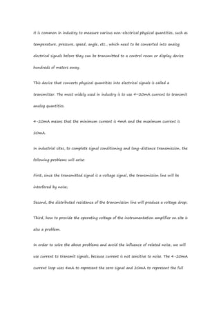
It is common in industry to measure various non-electrical physical quantities, such as temperature, pressure, speed, angle, etc., which need to be converted into analog electrical signals before they can be transmitted to a control room or display device hundreds of meters away. This device that converts physical quantities into electrical signals is called a transmitter. The most widely used in industry is to use 4~20mA current to transmit analog quantities.

Recommended
Recommended
More Related Content
Similar to Why Does The Transmitter Use 4-20mA Why Choose 4-20mA Instead Of 0-20mA
Similar to Why Does The Transmitter Use 4-20mA Why Choose 4-20mA Instead Of 0-20mA (20)
More from Dalian Zero Instrument Technology Co., Ltd China
More from Dalian Zero Instrument Technology Co., Ltd China (20)
Recently uploaded
Recently uploaded (20)
Why Does The Transmitter Use 4-20mA Why Choose 4-20mA Instead Of 0-20mA
- 1. It is common in industry to measure various non-electrical physical quantities, such as temperature, pressure, speed, angle, etc., which need to be converted into analog electrical signals before they can be transmitted to a control room or display device hundreds of meters away. This device that converts physical quantities into electrical signals is called a transmitter. The most widely used in industry is to use 4~20mA current to transmit analog quantities. 4-20mA means that the minimum current is 4mA and the maximum current is 20mA. In industrial sites, to complete signal conditioning and long-distance transmission, the following problems will arise: First, since the transmitted signal is a voltage signal, the transmission line will be interfered by noise; Second, the distributed resistance of the transmission line will produce a voltage drop; Third, how to provide the operating voltage of the instrumentation amplifier on site is also a problem. In order to solve the above problems and avoid the influence of related noise, we will use current to transmit signals, because current is not sensitive to noise. The 4-20mA current loop uses 4mA to represent the zero signal and 20mA to represent the full
- 2. scale of the signal. Signals lower than 4mA and higher than 20mA are used for alarms of various faults. You will definitely ask: Why choose 4-20mA instead of 0-20mA? It’s simple, if 0 is the minimum, then the open circuit fault will not be detected! So, why is it 4mA? During normal operation, the current signal will not be lower than 4mA. When the transmission line is disconnected due to a fault, the loop current drops to 0. 2mA is often taken as the disconnection alarm value. There are two reasons. One reason is to avoid interference, and the other reason is that 4-20mA uses a two-wire system, that is, the two lines are signal lines and power lines, and 4mA is used to provide the sensor with the static operating current of the circuit. How does this 4-20mA control loop work? 4-20mA constitutes the basic requirements: 24V power supply The transmitter controls the 4-20mA signal to vary proportionally to the process variable Indicators convert 4-20mA signals into corresponding process variables Indicator or controller I/O input resistor 250Ω shunt generates 1-5V input signal (Ohm’s Law: Voltage = Current * Resistance, 4-20 mA X 250 ohms = 1-5V) Usually:
- 3. 1) They convert the temperature signal of the thermocouple or thermal resistance sensor into a 4-20mA signal and then output it; 2) The controller then back-translates 4-20mA into a specific temperature value; 3) Based on this temperature value, the control loop controls the process terminal control components. Similarly, pressure transmitters in control loops are usually used to measure the pressure of the process medium: 1) The sensor senses the pressure, and the transmitter converts the signal into a 4-20mA signal; 2) The controller then back-translates the 4-20mA signal into a pressure value; 3) Based on the pressure value, the controller sends instructions to the valve to control the valve opening to achieve safety valve control to ensure that the container does not generate dangerous pressure. Common faults, causes and troubleshooting steps Wiring and terminal problems: bad terminals, insulation problems, corrosion and contamination of lines, etc.; Loop power supply: Noise interference, overvoltage and other problems may cause the loop to work abnormally; Control system I/O card failure;
- 4. transmitter; Sensor: damage to components, obstruction of measurement channels. 1. Verify 4-20mA signal Use the series method or use a milliamp current clamp meter to measure 4-20 mA signals: 1) Verify power supply 2) Find line problems 3) Find I/O problems 4) Find the problematic wiring terminal Troubleshooting steps: 1) Measure the mA value in the loop. If 0mA is measured, continue troubleshooting; 2) If there is no indication on the controller, it may be that the fuse of the I/O input is blown and the circuit has an open circuit fault. 2. Troubleshooting controller I/O problems: 4-20mA loop troubleshooting (alternative test) Transmitter replacement testing is a very good I/O failure analysis method, which uses the test equipment to output a standard signal to verify the control output.
- 5. Troubleshooting steps: 1) Disconnect the transmitter and connect the loop calibrator or process meter to the original transmitter location; 2) Set mA simulation and set the range to 4-20 mA; 3) Verify the correct value of the indicator and complete the test of the line, power supply and I/O in the same test; 4) If there is no indication on the controller, it may be that the fuse of the I/O input is blown and the circuit has an open circuit fault. Can be verified by measuring at 250Ω input. 3. Troubleshooting power supply problems Using a loop calibrator or multimeter, measure the loop supply voltage. Troubleshooting steps: 1) Measure the power supply, it should be approximately 24V. 2) If the measurement result is inconclusive, perform an alternative test. a. Disconnect device loop power
- 6. b. Connect the 24V loop power supply terminal of the loop calibrator or process meter at this location c. If the problem is resolved at this time, the device’s loop power supply may be defective or overloaded. 4. Line noise troubleshooting Line noise is caused by poor insulation performance, cable shielding failure, ground loop failure, critical power supply, wiring errors, etc. To capture and confirm noise signals, you can use a process multimeter with a multimeter function, or a multimeter, handheld oscilloscope and other equipment to find whether there are AC signals in the system. Under normal circumstances, there should be only a small amount of mV-level AC voltage present in the system.