Download to read offline

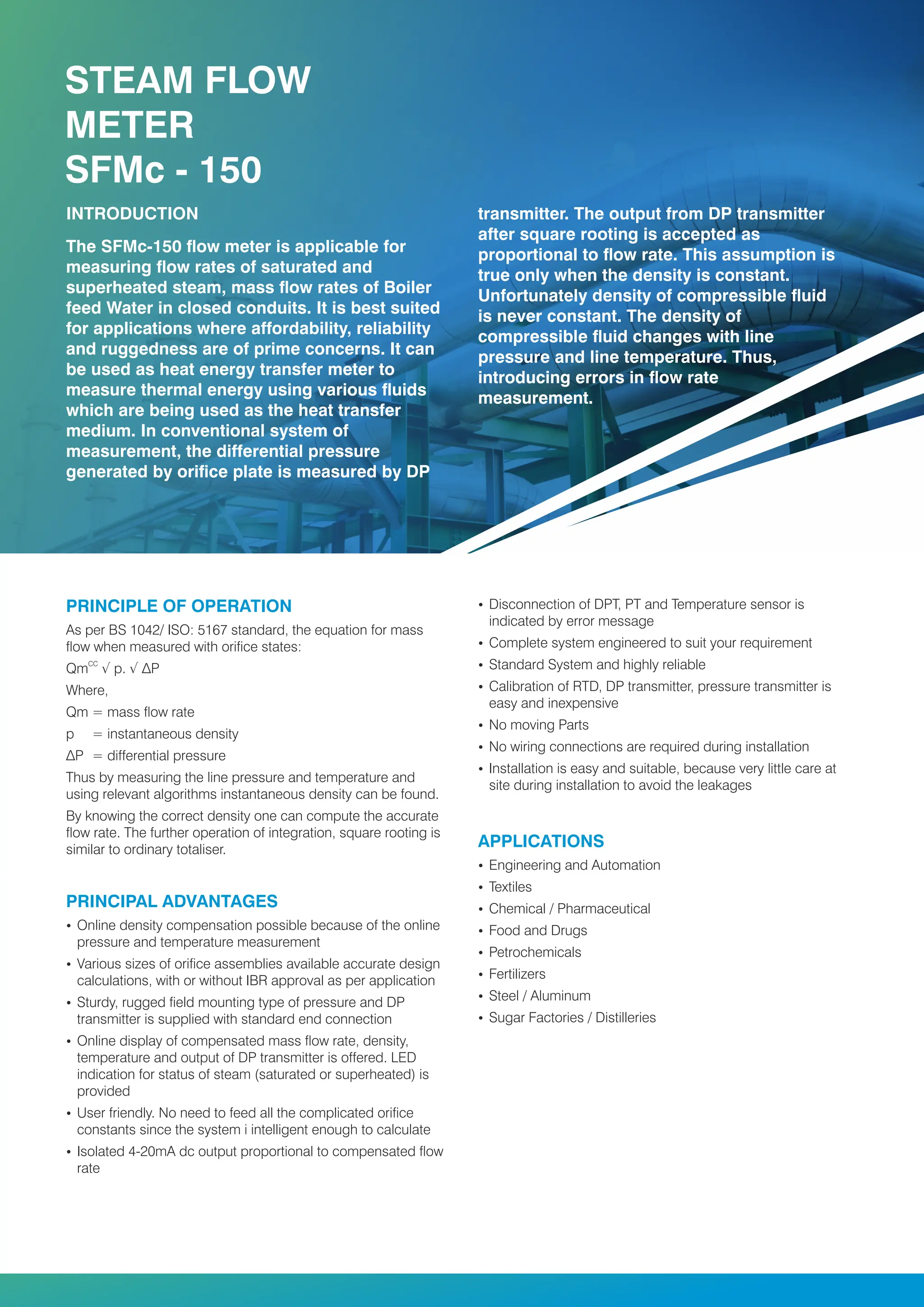


The SFMC-150 steam flow meter is designed for accurate measurement of saturated and superheated steam flow rates, utilizing online density compensation through direct measurement of pressure and temperature. It features user-friendly programming, data logging capabilities, and is suitable for a variety of industrial applications such as petrochemicals and pharmaceuticals. The device complies with BS 1042 and ISO 5167 standards and is recognized for its ease of installation and maintenance-free operation due to its lack of moving parts.