
Download to read offline

![4
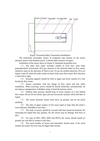
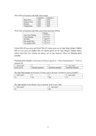
3. Technical Specifications of Products
3.1 Technical Specifications
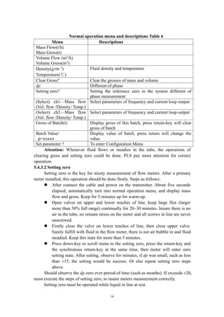
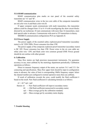
Table of Technical Specifications (Table 1)
Titles Technical Specifications
Mass flow accuracy ±[0.2% +(zero stability /flow rate×100%)]
Mass flow repeatability ±(1/2) ×[0.2% +(zero stability /flow rate×100%)]
Density range 0.2 g/cm3
~3.5g/cm3
Density accuracy ±0.002g/cm3
Temperature range -60℃~+200℃
Temperature accuracy ±1℃
Output of current loop 4mA~20mA
Output of frequency/pulse 0Hz~10kHz
Contactor capacity of a
Batch Control relay
24V/0.1A
Contactor form normal open
3.2 Other Specifications
Environmental Specifications (Table 2)
Titles Specifications
Temperature range of fluid -40℃~+200℃
Environmental temperature
range
0℃~+40℃
Environmental humidity ≤90% RH, non condensation
Atmospheric pressure range 86kPa~106kPa
Power supply of
transmitters
Essential safety Voltage: AC(220±10%)V,(50±5%)Hz
Composite Voltage: DC (24±10%) V
Power consumed <15W
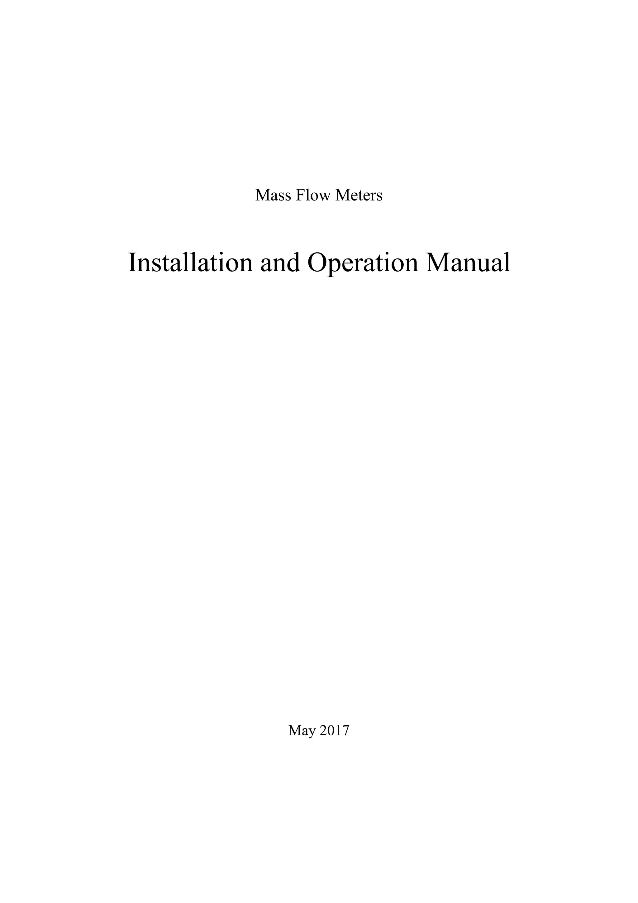
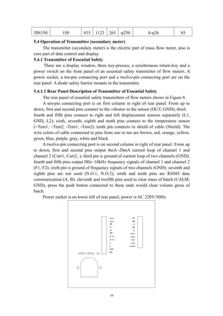
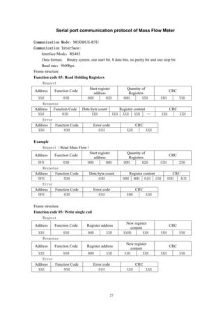
Specifications (Table 3)
Specs
Line Sizes
(mm)
Flow
Range (t/h)
Calibration
Range (t/h)
Max. Tube
Pressure (MPa)
Zero Stability
(t/hr)
Velocity
Parameter
(h m/t s)
DN1 1 0~0.04 0.004~0.04 30.0 0.000008 353.7
DN3 3 0~0.35 0.035~0.35 30.0 0.000067 39.3
DN6 6 0~0.7 0.07~0.7 30.0 0.00016 19.65
DN10 10 0~1.2 0.12~1.2 30.0 0.0002 4.912
DN15 15 0~6.4 0.64~6.4 4.0 0.0011 2.183
DN25 25 0~16 1.6~16 4.0 0.002 0.902
DN40 40 0~40 4~40 4.0 0.003 0.334
DN50 50 0~65 6.5~65 4.0 0.006 0.197
DN80 80 0~160 16~160 2.5 0.01 0.0873
DN100 100 0~250 25~250 2.5 0.015 0.0544](https://image.slidesharecdn.com/massflowmeter-180305084155/85/Mass-flowmeter-5-320.jpg)
![5
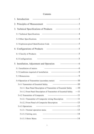
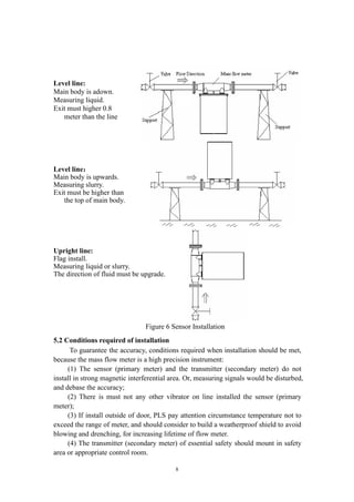
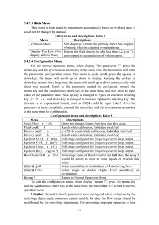
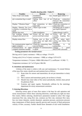
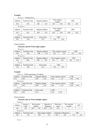
DN150 150 0~550 55~550 2.5 0.03 0.0239
3.3 Explosion-proof Identification Code
Teble of Explosion-proof identification code (Table 4)
Form of Explosion-proof Identification Code
Essential safety Exib[ib]IIBT4
Composite Exdib[ib]IIBT4
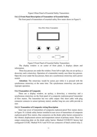
4. Configurations of Products
4.1 Classify of Products
Products specs are divided to eleven based on nominal line sizes: DN1, DN3,
DN6, DN10, DN15, DN25, DN40, DN50, DN80, DN100, DN150 (units: mm).
4.2 Configurations
Figure 1 Sensors (primary meter)
Figure 2 Essential Safety Transmitter Figure 3 Composite Transmitter and Sensor
Every meter consists of two parts: the sensor (primary meter) and the transmitter
(secondary meter).
The sensor (primary meter) is machinery part of mass flow meter. There are a
vibrator, two displacement sensors and a temperature sensor in it.
The transmitter (secondary meter) is display part of the meter, also is electrical](https://image.slidesharecdn.com/massflowmeter-180305084155/85/Mass-flowmeter-6-320.jpg)
![20
such as length of cable, signal format, demand for explosion-proof, environment and
so on.
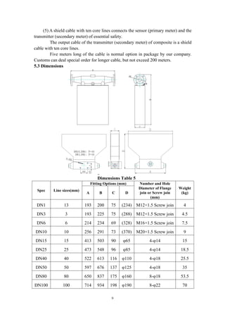
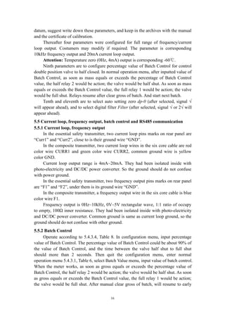
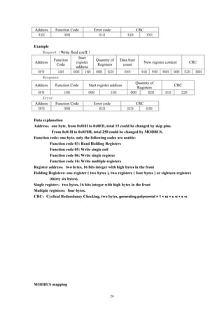
(1) Primary select a nominal line size of mass flow meters
User or engineer primary select a spec of mass flow meters base on flow range of
fluid and inner diameter, referring to Table 3.
Example: such as flow range: 8~20t/h, inner diameter: Φin = 50mm, viscosity of
fluid: μ = 25cP, specific gravity: S = 0.8. So primary select DN50 mass flow meters
referring to Table 3, nominal line size: 50mm, maximum flow rate: 80t/h. (if user has
known motive viscosity value mm2
/s of fluid, could obtain absolute viscosity value μ
with multiply by fluid density or specific gravity.)
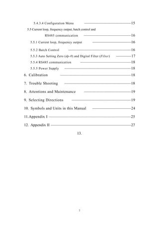
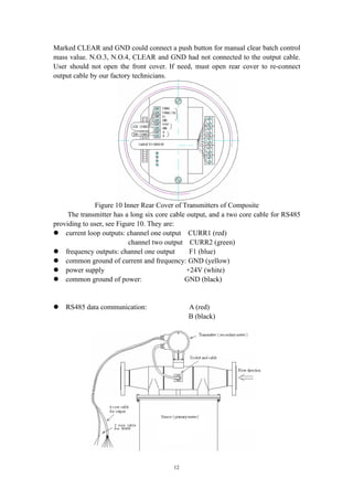
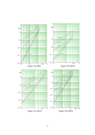
(2) Check pressure drop
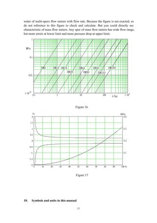
Figure 15 is curves of flow rate / pressure drop with different viscosity based on
water (μ=1) of multi-specs of flow meters. In this example, find the point of 20t/h in
the abscissa of Figure 15f, draw a parallel with the ordinate through this point
intersect with curve of μ= 25, got point Q, draw a parallel with the abscissa through
the point Q intersect with the ordinate, got point P, we can read out point P pressure
drop 0.08MPa.
This pressure drop called figure pressure drop, sign as ΔPF = 0.08MPa.
(3) Calculate real pressure drop using fluid specific gravity S
Real pressure drop of fluid: ΔPR = ΔPF / S = 0.08MPa / 0.8 = 0.1MPa
Commonly, this pressure drop would meet with demand of design and
engineering. Next, check if tube pressure, temperature range meets with demands.
(4) Check velocity of flow
If there is the limit flow velocity by design and engineering, you have to
calculate flow velocity using this formula:
V = Kv × Qm / C.
Herein: maximum flow rate Qm = 20 (t/h);
Velocity parameter (see Table 1) Kv = 0.197 (h m/t s);
Ratio of density of fluid by water (or specific gravity) C = S = 0.8.
Then, got velocity: V = 20 ×0.197 / 0.8 = 4.925 m/s.
For flammability and explosive chemical fluid, maximum velocity must lower
the limit by safety and engineering, to avoid static produced.
(5)If viscosity more than 25cP, such as 500cP, then find pressure drop 0.8MPa
at same flow rate reference to Figure 15f. If this pressure drop could not permit by
design or engineering, must select a large line size of mass flow meters, such as DN80.
Then repeat above(1)(2)(3)(4)to calculate and check.
( 6 ) After selecting right line size of mass flow meters, should check if
measurement accuracy met the demands.
Accuracy = ±[0.2% +(zero stability /flow rate×100%)]](https://image.slidesharecdn.com/massflowmeter-180305084155/85/Mass-flowmeter-21-320.jpg)
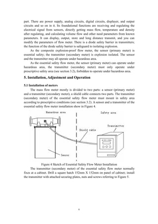
The document provides an installation and operation manual for ZERO100M Mass Flow Meters. It discusses the principles of measurement, technical specifications, configurations, and installation, adjustment, and operation of the meters. The meters consist of a sensor that measures flow parameters and a transmitter that receives and processes the sensor signals. The transmitter is available in essential safety and composite models to meet hazardous area requirements.


![Gu641 B Genset Control Operation Manual[1]](https://cdn.slidesharecdn.com/ss_thumbnails/gu641bgensetcontroloperationmanual1-13324716217433-phpapp02-120322220238-phpapp02-thumbnail.jpg?width=640&height=640&fit=bounds)


