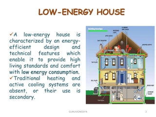
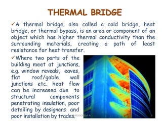
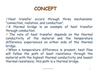
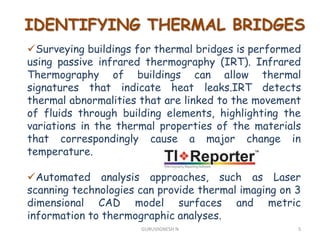
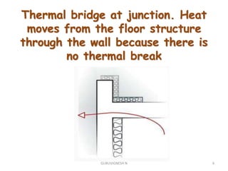
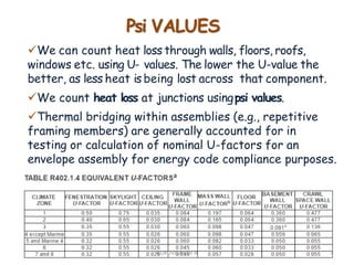
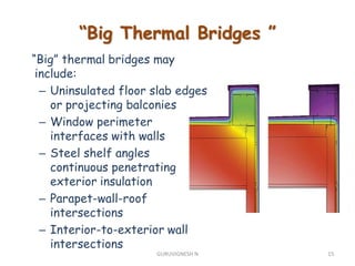
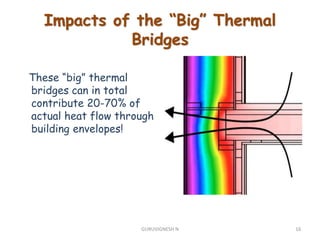
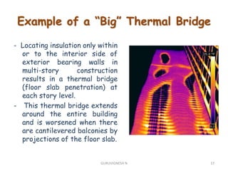
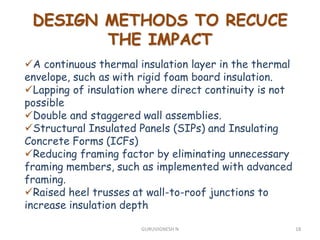
THERMAL BRIDGING IN LOW
ENERGY BUILDING
Submitted by
GURUVIGNESH N
Reg. No :910018413004
M.E.-STRUCTURAL ENGINEERING
(FULL TIME)
ANNAUNIVERSITY REGIONAL
CAMPUS MADURAI
1GURUVIGNESH N
LOW-ENERGY HOUSE
A low-energy house is
characterized by an energy-
efficient design and
technical features which
enable it to provide high
living standards and comfort
with low energy consumption.
Traditional heating and
active cooling systems are
absent, or their use is
secondary.
2GURUVIGNESH N
A thermal bridge, also called a cold bridge, heat
bridge, or thermal bypass, is an area or component of an
object which has higher thermal conductivity than the
surrounding materials, creating a path of least
resistance for heat transfer.
THERMAL BRIDGE
Where two parts of the
building meet at junctions,
e.g. window reveals, eaves,
flat roof/gable wall
junctions etc. heat flow
can be increased due to
structural components
penetrating insulation, poor
detailing by designers and
poor installation by trades. 3GURUVIGNESH N
CONCEPT
Heat transfer occurs through three mechanisms:
“convection, radiation, and conduction”.
A thermal bridge is an example of heat transfer
through conduction.
 The rate of heat transfer depends on the thermal
conductivity of the material and the temperature
difference experienced on either side of the thermal
bridge.
When a temperature difference is present, heat flow
will follow the path of least resistance through the
material with the highest thermal conductivity and lowest
thermal resistance; this path is a thermal bridge.
4GURUVIGNESH N
IDENTIFYING THERMAL BRIDGES
Surveying buildings for thermal bridges is performed
using passive infrared thermography (IRT). Infrared
Thermography of buildings can allow thermal
signatures that indicate heat leaks.IRT detects
thermal abnormalities that are linked to the movement
of fluids through building elements, highlighting the
variations in the thermal properties of the materials
that correspondingly cause a major change in
temperature.
Automated analysis approaches, such as Laser
scanning technologies can provide thermal imaging on 3
dimensional CAD model surfaces and metric
information to thermographic analyses.
5GURUVIGNESH N
Thermal bridge at junction. Heat
moves from the floor structure
through the wall because there is
no thermal break
6GURUVIGNESH N
Psi VALUES
We can count heat loss through walls, floors, roofs,
windows etc. using U- values. The lower the U-value the
better, as less heat is being lost across that component.
We count heat loss at junctions usingpsi values.
Thermal bridging within assemblies (e.g., repetitive
framing members) are generally accounted for in
testing or calculation of nominal U-factors for an
envelope assembly for energy code compliance purposes.
7GURUVIGNESH N
IMPACTS OF THERMAL BRIDGING
Thermal bridging can result in increased energy
required to heat or cool a conditioned space due to winter
heat loss and summer heat gain.
At interior locations near thermal bridges, occupants
may experience thermal discomfort due to the difference
in temperature.
Additionally, when the temperature difference between
indoor and outdoor space is large and there is warm and
humid air indoors, such as the conditions experienced in
the winter, there is a risk of condensation in the building
envelope due to the cooler temperature on the interior
surface at thermal bridge locations.
8GURUVIGNESH N
Important Factors
The magnitude of impact of thermal bridging depends
on a number of factors:
– The type of structural material (wood, steel,
concrete, masonry)
– The details used to interface or interconnect
assemblies or make component attachments to the
structure.
– The location of insulation materials on or within
the assembly
– The thermal characteristics of elements
penetrating insulation layers and the continuity of
the heat flow path
9GURUVIGNESH N
The impact of thermal
bridges is often
disproportionate to the
actual area of the thermal
bridge itself relative to
the overall assembly area.
– A “small” thermal bridge
does not necessarily
mean it has a “small”
impact
Important Factors
10GURUVIGNESH N
THE KNOWLEDGE
GAP
Designers not
adequately
educated on
principles of
good building
fabric design
Poor quality
of
information
delivered to
site
Site trades not
adequately
educated on
principles of
good building
fabric design
(askWHY not
WHAT)
Value
engineering on
site not
supported by
informed
decisions or
analysis
Sub-standard
building
quality
11GURUVIGNESH N
Examples or poor design or construction
12GURUVIGNESH N
Three Categories of Thermal
Bridges & Code Compliance
Implications
Thermal bridging that occurs
at the interface of assemblies
or envelope components is
generally not accounted for
and is often ignored for code
compliance.
– These are known as “linear
thermal bridges”
– The impact on thermal
performance of a building
can be very large
Concrete slab
penetrating wall
“linear thermal bridges”
13GURUVIGNESH N
“point thermal bridges”
Thermal bridging that occurs at
“points” within an assembly (e.g.,
many small cladding connections,
a beam or pipe penetration, etc)
may or may not be fully
accounted for in testing or
calculation of U-factors.
– These are known as “point
thermal bridges”
– The thermal performance
impacts are often non-
negligible.
Steel column going
through roof
14GURUVIGNESH N
“Big” thermal bridges may
include:
– Uninsulated floor slab edges
or projecting balconies
– Window perimeter
interfaces with walls
– Steel shelf angles
continuous penetrating
exterior insulation
– Parapet-wall-roof
intersections
– Interior-to-exterior wall
intersections
“Big Thermal Bridges ”
15GURUVIGNESH N
These “big” thermal
bridges can in total
contribute 20-70% of
actual heat flow through
building envelopes!
Impacts of the “Big” Thermal
Bridges
16GURUVIGNESH N
- Locating insulation only within
or to the interior side of
exterior bearing walls in
multi-story construction
results in a thermal bridge
(floor slab penetration) at
each story level.
- This thermal bridge extends
around the entire building
and is worsened when there
are cantilevered balconies by
projections of the floor slab.
Example of a “Big” Thermal Bridge
17GURUVIGNESH N
DESIGN METHODS TO RECUCE
THE IMPACT
A continuous thermal insulation layer in the thermal
envelope, such as with rigid foam board insulation.
Lapping of insulation where direct continuity is not
possible
Double and staggered wall assemblies.
Structural Insulated Panels (SIPs) and Insulating
Concrete Forms (ICFs)
Reducing framing factor by eliminating unnecessary
framing members, such as implemented with advanced
framing.
Raised heel trusses at wall-to-roof junctions to
increase insulation depth
18GURUVIGNESH N
WALL PENETRATING ROOF
INSULATION
19GURUVIGNESH N
ANALYSIS METHOD AND
CHALLENGES
Due to their significant impacts on heat transfer,
correctly modeling the impacts of thermal bridges is
important to estimate overall energy use. Thermal
bridges are characterized by multi-dimensional heat
transfer, and therefore they cannot be adequately
approximated by steady-state one-dimensional (1D)
models of calculation typically used to estimate the
thermal performance of buildings in most building
energy simulation tools
20GURUVIGNESH N
The impact of mechanical
fastening on the U-factor
is about 2-3% increase for
carbon steel fasteners
with metal cap washers
(less for stainless steel)
– This assumes a typical
fastening schedule for
mechanically attached
insulation layers and
roof membrane.
Mechanically fastened above-deck
roof insulation and membrane
21GURUVIGNESH N
SOLUTIONS:
– Use of recessed plastic insulation
fasteners to fasten above-deck
roof insulation may reduce thermal
bridging impact by as much as
30%.
– Attachment to a wood roof deck
instead of metal deck would have a
similar magnitude of benefit in
mitigating thermal bridging
through fasteners.
– The above mitigating actions
should not be considered as
cumulative.
Mechanically fastened above-deck
roof insulation and membrane
22GURUVIGNESH N
 Assemblies with exterior
experience an increase in
nominal U-factor of about 3-
7%
 Assemblies without exterior CI
experience an increase in
nominal U-factor of about 1%.
Wood Frame Wall Assemblies
23GURUVIGNESH N
SOLUTIONS:
– While impacts are small for
wood framing, minimizing
connection points through ci
can provide a small thermal
performance improvement.
– Placing ci over heavily
fastened shear wall panels will
help to mitigate the additional
heat flow through the
structural shear panel
fastenings.
Wood Frame Wall Assemblies
24GURUVIGNESH N
Mass wall assembly with
mass layers (e.g., brick
cavity wall, concrete
sandwich panels, etc.):
– For mass walls the
relative increase in
U-factor ranges from
28% to 44% when
carbon steel metal
ties are used.
Mass Wall (concrete/masonry)
Assemblies
25GURUVIGNESH N
SOLUTIONS:
– The use of stainless steel
ties (or other less
conductive tie designs)
– Minimizing the number of
ties
– Using ties that are
thermally broken or of low
thermal conductivity
material (e.g., carbon fiber,
etc.)
Mass Wall (concrete/masonry)
Assemblies
26GURUVIGNESH N
THANK YOU
27GURUVIGNESH N

THERMAL BRIDGING

  • 1.
    THERMAL BRIDGING INLOW ENERGY BUILDING Submitted by GURUVIGNESH N Reg. No :910018413004 M.E.-STRUCTURAL ENGINEERING (FULL TIME) ANNAUNIVERSITY REGIONAL CAMPUS MADURAI 1GURUVIGNESH N
  • 2.
    LOW-ENERGY HOUSE A low-energyhouse is characterized by an energy- efficient design and technical features which enable it to provide high living standards and comfort with low energy consumption. Traditional heating and active cooling systems are absent, or their use is secondary. 2GURUVIGNESH N
  • 3.
    A thermal bridge,also called a cold bridge, heat bridge, or thermal bypass, is an area or component of an object which has higher thermal conductivity than the surrounding materials, creating a path of least resistance for heat transfer. THERMAL BRIDGE Where two parts of the building meet at junctions, e.g. window reveals, eaves, flat roof/gable wall junctions etc. heat flow can be increased due to structural components penetrating insulation, poor detailing by designers and poor installation by trades. 3GURUVIGNESH N
  • 4.
    CONCEPT Heat transfer occursthrough three mechanisms: “convection, radiation, and conduction”. A thermal bridge is an example of heat transfer through conduction.  The rate of heat transfer depends on the thermal conductivity of the material and the temperature difference experienced on either side of the thermal bridge. When a temperature difference is present, heat flow will follow the path of least resistance through the material with the highest thermal conductivity and lowest thermal resistance; this path is a thermal bridge. 4GURUVIGNESH N
  • 5.
    IDENTIFYING THERMAL BRIDGES Surveyingbuildings for thermal bridges is performed using passive infrared thermography (IRT). Infrared Thermography of buildings can allow thermal signatures that indicate heat leaks.IRT detects thermal abnormalities that are linked to the movement of fluids through building elements, highlighting the variations in the thermal properties of the materials that correspondingly cause a major change in temperature. Automated analysis approaches, such as Laser scanning technologies can provide thermal imaging on 3 dimensional CAD model surfaces and metric information to thermographic analyses. 5GURUVIGNESH N
  • 6.
    Thermal bridge atjunction. Heat moves from the floor structure through the wall because there is no thermal break 6GURUVIGNESH N
  • 7.
    Psi VALUES We cancount heat loss through walls, floors, roofs, windows etc. using U- values. The lower the U-value the better, as less heat is being lost across that component. We count heat loss at junctions usingpsi values. Thermal bridging within assemblies (e.g., repetitive framing members) are generally accounted for in testing or calculation of nominal U-factors for an envelope assembly for energy code compliance purposes. 7GURUVIGNESH N
  • 8.
    IMPACTS OF THERMALBRIDGING Thermal bridging can result in increased energy required to heat or cool a conditioned space due to winter heat loss and summer heat gain. At interior locations near thermal bridges, occupants may experience thermal discomfort due to the difference in temperature. Additionally, when the temperature difference between indoor and outdoor space is large and there is warm and humid air indoors, such as the conditions experienced in the winter, there is a risk of condensation in the building envelope due to the cooler temperature on the interior surface at thermal bridge locations. 8GURUVIGNESH N
  • 9.
    Important Factors The magnitudeof impact of thermal bridging depends on a number of factors: – The type of structural material (wood, steel, concrete, masonry) – The details used to interface or interconnect assemblies or make component attachments to the structure. – The location of insulation materials on or within the assembly – The thermal characteristics of elements penetrating insulation layers and the continuity of the heat flow path 9GURUVIGNESH N
  • 10.
    The impact ofthermal bridges is often disproportionate to the actual area of the thermal bridge itself relative to the overall assembly area. – A “small” thermal bridge does not necessarily mean it has a “small” impact Important Factors 10GURUVIGNESH N
  • 11.
    THE KNOWLEDGE GAP Designers not adequately educatedon principles of good building fabric design Poor quality of information delivered to site Site trades not adequately educated on principles of good building fabric design (askWHY not WHAT) Value engineering on site not supported by informed decisions or analysis Sub-standard building quality 11GURUVIGNESH N
  • 12.
    Examples or poordesign or construction 12GURUVIGNESH N
  • 13.
    Three Categories ofThermal Bridges & Code Compliance Implications Thermal bridging that occurs at the interface of assemblies or envelope components is generally not accounted for and is often ignored for code compliance. – These are known as “linear thermal bridges” – The impact on thermal performance of a building can be very large Concrete slab penetrating wall “linear thermal bridges” 13GURUVIGNESH N
  • 14.
    “point thermal bridges” Thermalbridging that occurs at “points” within an assembly (e.g., many small cladding connections, a beam or pipe penetration, etc) may or may not be fully accounted for in testing or calculation of U-factors. – These are known as “point thermal bridges” – The thermal performance impacts are often non- negligible. Steel column going through roof 14GURUVIGNESH N
  • 15.
    “Big” thermal bridgesmay include: – Uninsulated floor slab edges or projecting balconies – Window perimeter interfaces with walls – Steel shelf angles continuous penetrating exterior insulation – Parapet-wall-roof intersections – Interior-to-exterior wall intersections “Big Thermal Bridges ” 15GURUVIGNESH N
  • 16.
    These “big” thermal bridgescan in total contribute 20-70% of actual heat flow through building envelopes! Impacts of the “Big” Thermal Bridges 16GURUVIGNESH N
  • 17.
    - Locating insulationonly within or to the interior side of exterior bearing walls in multi-story construction results in a thermal bridge (floor slab penetration) at each story level. - This thermal bridge extends around the entire building and is worsened when there are cantilevered balconies by projections of the floor slab. Example of a “Big” Thermal Bridge 17GURUVIGNESH N
  • 18.
    DESIGN METHODS TORECUCE THE IMPACT A continuous thermal insulation layer in the thermal envelope, such as with rigid foam board insulation. Lapping of insulation where direct continuity is not possible Double and staggered wall assemblies. Structural Insulated Panels (SIPs) and Insulating Concrete Forms (ICFs) Reducing framing factor by eliminating unnecessary framing members, such as implemented with advanced framing. Raised heel trusses at wall-to-roof junctions to increase insulation depth 18GURUVIGNESH N
  • 19.
  • 20.
    ANALYSIS METHOD AND CHALLENGES Dueto their significant impacts on heat transfer, correctly modeling the impacts of thermal bridges is important to estimate overall energy use. Thermal bridges are characterized by multi-dimensional heat transfer, and therefore they cannot be adequately approximated by steady-state one-dimensional (1D) models of calculation typically used to estimate the thermal performance of buildings in most building energy simulation tools 20GURUVIGNESH N
  • 21.
    The impact ofmechanical fastening on the U-factor is about 2-3% increase for carbon steel fasteners with metal cap washers (less for stainless steel) – This assumes a typical fastening schedule for mechanically attached insulation layers and roof membrane. Mechanically fastened above-deck roof insulation and membrane 21GURUVIGNESH N
  • 22.
    SOLUTIONS: – Use ofrecessed plastic insulation fasteners to fasten above-deck roof insulation may reduce thermal bridging impact by as much as 30%. – Attachment to a wood roof deck instead of metal deck would have a similar magnitude of benefit in mitigating thermal bridging through fasteners. – The above mitigating actions should not be considered as cumulative. Mechanically fastened above-deck roof insulation and membrane 22GURUVIGNESH N
  • 23.
     Assemblies withexterior experience an increase in nominal U-factor of about 3- 7%  Assemblies without exterior CI experience an increase in nominal U-factor of about 1%. Wood Frame Wall Assemblies 23GURUVIGNESH N
  • 24.
    SOLUTIONS: – While impactsare small for wood framing, minimizing connection points through ci can provide a small thermal performance improvement. – Placing ci over heavily fastened shear wall panels will help to mitigate the additional heat flow through the structural shear panel fastenings. Wood Frame Wall Assemblies 24GURUVIGNESH N
  • 25.
    Mass wall assemblywith mass layers (e.g., brick cavity wall, concrete sandwich panels, etc.): – For mass walls the relative increase in U-factor ranges from 28% to 44% when carbon steel metal ties are used. Mass Wall (concrete/masonry) Assemblies 25GURUVIGNESH N
  • 26.
    SOLUTIONS: – The useof stainless steel ties (or other less conductive tie designs) – Minimizing the number of ties – Using ties that are thermally broken or of low thermal conductivity material (e.g., carbon fiber, etc.) Mass Wall (concrete/masonry) Assemblies 26GURUVIGNESH N
  • 27.