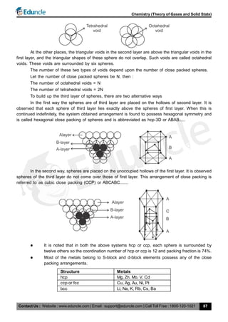
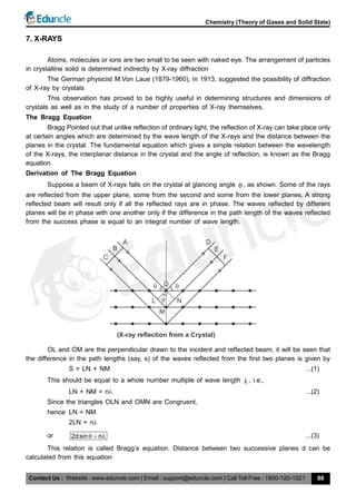
This document provides information about the kinetic theory of gases and gas laws. It begins by outlining the key postulates of the kinetic theory, including that gases are composed of molecules in constant random motion that exert pressure during collisions with container walls. It then derives the kinetic gas equation and shows how the ideal gas law and other gas laws can be obtained from it. The document also discusses real gas behavior and Van der Waals' equation of state, which introduces corrections for molecular volume and intermolecular forces.

![Contact Us : Website : www.eduncle.com | Email : support@eduncle.com | Call Toll Free : 1800-120-1021
Chemistry (Theory of Gases and Solid State)
101
8. LATTICE ENERGY
It is defined as the amount of energy released when cations and anions in their gaseous state
are bought together from infinite separation to form a crystal.
U
M (g) X (g) MX(s)
; U = lattice Energy
The theoretical treatment of ionic lattice energy was given by M.Born and A. Lande. This treatment
has been discussed below.
2
A
0
o o
MN Z Z e 1
U 1
4 r n
This is the Born-Lande equation for lattice energy of an ionic crystal.
here M = Modelung Constant
NA
= Avogadro’s Number
Z+ = Charge on Cation
Z– = Charge on Anion
o
= Dielectric Constant
ro
= Distance
n = Born exponent
The Born exponent n depend upon the type of the ion involved. Large ions having relatively
higher densities have larger values of n.
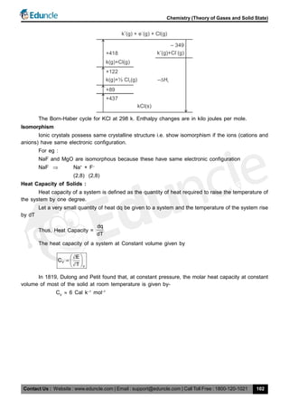
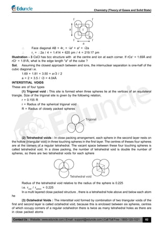
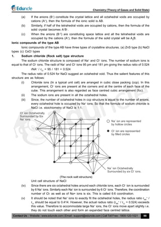
Experimental values of the lattice energy are obtained by using Born-Haber cycle,
A typical cycle, for potassium chloride, is shown in figure.
Consists of the following steps.
1. Sublimation of K(s) = H (kJ mol–1
) + 89 [dissociation enthalpy of K(s)]
2. Dissociation of
1
2
Cl2
(g) = +122 [
1
2
× dissociation enthalpy of Cl2
(g)]
3. Ionization of K(g) = +418 [ionization enthalpy of K(g)]
4. Electron attachment to Cl(g) = –349 [electron gain enthalpy Cl(g)
5. Formation of solid form gas = –HL
/(kJ mol–1
)
6. Decomposition of compound = +437 [negative of enthalpy of formation of KCl(s)]
Because the sum of these enthalpy changes is equal to zero, we can infer from
89 + 122 + 418 – 349 – H2
/(kJ mol–1
) + 437 = 0
that HL
= +717 kJ mol–1
Some lattice energies obtained in this way are listed in following table-
HL
/(kJ/mol–1
)
NaF 787
NaBr 751
MgO 3850
MgS 3406](https://image.slidesharecdn.com/3-200424130541/85/theory-of-gases-and-solid-state-41-320.jpg)