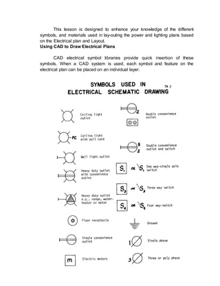
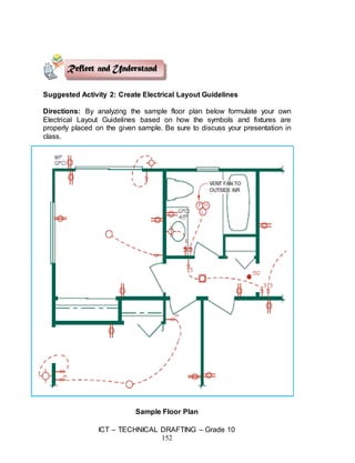
1. ICT β TECHNICAL DRAFTING β Grade 10
144
Content Standard Performance Standard
The learner demonstrates
understanding of concepts and
underlying principles in drafting
electrical and electronic layout and
details using Computer-Aided Design
(CAD).
The learner independently drafts
electrical and electronic layout and
details following the job requirements
using Computer-Aided Design (CAD).
Quarter III Time Allotment: 8 hrs.
MODULE 5
DRAFTING ELECTRICAL AND ELECTRONIC LAYOUT AND
DETAILS USING COMPUTER-AIDED DESIGN (CAD)
Introduction
Technology and Livelihood Education (TLE) is one of the nomenclature
in the implementation of the K to 12 Basic Education Program (BEP)
composed of four components namely: Agri-Fishery Arts, Home Economics,
Industrial Arts and Information and Communication Technology (ICT). In this
module, the focus is on Drafting Electrical and Electronic Layout and
Details using CAD.
In this course, you will be introduced to different learning activities that
will prepare you to be skillful before you to do actual work as a draftsman and
to be more confident to start your own CAD business.
This module is specifically designed to hone your knowledge and skills
specifically on Process and Delivery where you have a hands-on activities
as you go along. Learning procedures are divided into different sections such
as: What to Know, What to Process, What to Reflect and Understand and
What to Transfer.
So, explore and experience the lessons in Electrical and Electronic
Layout and Details using CAD and be a step closer to being a draftsman.
2. ICT β TECHNICAL DRAFTING β Grade 10
145
ENJOY YOUR JOURNEY!
Objectives:
Upon completion of this module, you are expected to:
οΆ draft electrical plans and layouts; and
οΆ draft auxiliary systems and layout using CAD.
*****
Pre-Assessment:
You will be challenged to recall your prior knowledge and experiences
about drafting electrical and electronic layout details. This phase will guide
you in assessing yourself by answering questions that relate with the basics
of drafting electrical and electronic layout and details using CAD.
Part I: Multiple Choice
Directions: Choose the letter of the best answer then write it in your
notebook.
1. What does the fillet command create?
A. Sharp Corners C. Round and Sharp Corners
B. Round Corners D. A boneless fish
2. How does a polar array create new objects?
A. In a grid pattern C. In a straight line
B. In a circular pattern D. In a northern pattern
3. ICT β TECHNICAL DRAFTING β Grade 10
146
3. The distances of a chamfer are --
A. always different. C. always the same.
B. sometimes different. D. never the same.
4. When should you use snaps?
A. when making dimensions C. when creating hatch
B. when drawing lines only D. when drawing arcs and circles
5. How many layer/s should there be in a drawing?
A. One C. Ten
B. One for each object D. As many as needed
6. When do you need to change the height of your text?
A. Only when you start the drawing
B. Only in a special text dialog box
C. When you are starting the Text command
D. You can't, it is pre-set by AutoCAD
7. What does scaling do to objects?
A. Makes them bigger C. Makes them smaller
B. Stretches them D. Duplicates them
8. How many view/s do you need to show in an Orthographic Projection?
A. 1 B. 2 C. 3 D. As many as are needed
9. When should you use a hatch pattern for section views?
A. When showing a steel pattern C. To make the drawing accurate
B. To emphasize floor area D. To specify materials to be used
10. What is the 3 character file extension name of an AutoCAD drawing?
A. dwg B. drw C. cad D. aut
Skills Assessment
Direction: Listed below are some of the most important skills that you must
possess in order to render quality service when you enter the real world of
drafting electrical plans and lay-out.
Put a check mark that corresponds to your personal skills assessment.
No Knowledge β means that you are not yet familiar with the skills stated.
A little β means you have skills but appeared to be inadequate.
A lot β means that you already possess the desired skills.
Feel free to answer each skill. Write the answers in your notebook.
4. ICT β TECHNICAL DRAFTING β Grade 10
147
Skills in Drafting Electrical Plans and
Layout
No
Knowledge
A
Little
A
Lot
I know how to draft lighting and power layouts
according to electrical drafting standards.
I can place riser diagram and circuiting symbols
in electrical plans and layouts.
I can indicate legend and general notes
according to local power service provider.
I know how to layout fire alarm and protection
system symbols in the auxiliary system and
layout plan according to Fire Code.
I can layout electronic and communication
devices according to electrical drafting
requirements.
Learning Goals and Targets:
After reading the introduction and carefully answering the pre
assessment skills test, you have now some ideas of what you will be dealing
with in this module. Now prepare to set your goals and targets for this module
by completing the activity below. Write your answer in your notebook.
My goals are:
Goal 4
Goal 3
Goal 2
Goal 1
5. ICT β TECHNICAL DRAFTING β Grade 10
148
My targets are:
Introduction
Electrical layout can be placed on the floor plan with all the other
symbols, information, and dimensions. This is a common practice on simple
floor plans where the addition of the electrical symbols does not
overcomplicate the drawing. Another option is to draw electrical plans on a
separate sheet that displays the floor plan walls and key symbols, such as
doors, windows, stairs, furniture, cabinets, and room labels.
Through this module, you will learn how to draw diagrams of electrical
and electronic circuits, proper symbols, layout, and other details using CAD.
Computer-aided design provides an excellent tool for creating electrical plans
after the floor plans are drawn. Not needed floor plan layers are turned off or
frozen with electrical layers turned on to create the electrical plan. It is easy to
create a separate drawing from the key elements of the base drawing in this
manner.
Lesson 1: Draft Electrical Plans and Lay-outs
Know
Target 1
Target 2
Target 3
6. ICT β TECHNICAL DRAFTING β Grade 10
149
This lesson is designed to enhance your knowledge of the different
symbols, and materials used in lay-outing the power and lighting plans based
on the Electrical plan and Layout.
Using CAD to Draw Electrical Plans
CAD electrical symbol libraries provide quick insertion of these
symbols. When a CAD system is used, each symbol and feature on the
electrical plan can be placed on an individual layer.
7. ICT β TECHNICAL DRAFTING β Grade 10
150
Prepare Electrical Plan using CAD
The electrical plan is prepared as a separate floor plan drawing,
named Electrical Plan. If you are creating a separate electrical plan, draw the
plan as described in the following steps and use the CAD layering system as
needed.
In architectural CAD programs, you can select symbols from pull-down
menus, icon menus, dialog boxes, and tablet menus. These software
programs provide you with maximum variety and flexibility to create a high-
quality electrical plan in an efficient manner.
Most of the common electrical symbols are provided with the software
of many of the CAD programs. When these symbols are available, you may
select the desired symbol from a menu, dialog box, palette, or library and
insert the symbol into position on the drawing. In the event that a desired
electrical symbol is not available, you are often given tools to create custom
electrical symbol libraries.
AutoCAD, for example, includes a powerful drawing information
manager called Design Center. A number of symbol libraries are installed with
AutoCAD that are available as drawing (.dwg) files. Numerous different files
contain architectural symbols and other types of content. The symbols in each
library can be accessed in Design Center and dragged and dropped into your
drawing.
Revit, an Autodesk, Inc. product, is an architectural modelling software
that also includes a number of parametric electrical symbols. These
parametric symbols when they are attached to ceiling and wall objects. If the
ceiling or wall objects are modified, the electrical symbols react to the
changes such as moving with the wall or ceiling. There are also a number of
online resources with electrical symbols in different CAD file formats for use in
your floor plans.
8. ICT β TECHNICAL DRAFTING β Grade 10
151
to
Suggested Activity 1: Features and Sequence of Creating CAD Electrical
Plan
1. Switch locations labeled with proper placement and identification, such
as three-way, four-way, or dimmer.
2. Inside and outside light fixture locations.
3. Recessed light fixture locations.
4. Fluorescent light fixtures
5. Switch legs drawn with dashed lines.
6. Duplex convenience outlets located based on code requirements.
7. Kitchen and bath GFCI outlets.
8. Exterior duplex convenience outlets, specifying weatherproof and
GFCI.
9. Outlets for refrigerator, microwave on a separate circuit, garbage
disposal with switch, dishwasher, trash compactor, clothes washer.
10.Exhaust fans.
11.Smoke detectors.
12.Utility and appliance outlets: Furnace, clothes dryer, range, ovens, and
water heater shown and labeled.
13.Outlets are 200-V for electric appliances as needed, or gas and 220-V
outlets.
14.Garage door junction boxes with switches for automatic door openers.
15.Television, telephone, separate Internet jack, and computer outlets
shown and labeled on separate circuits.
16.Vacuum system outlets located and labeled.
17.Circuit panel location, and specifications.
18.Door buzzer and chime location.
19.Smoke detectors at each bedroom or sleeping area.
20.Review all specific notes.
21.General notes.
22.Drawing title and scale.
23.Title block information.
Process
9. ICT β TECHNICAL DRAFTING β Grade 10
152
Suggested Activity 2: Create Electrical Layout Guidelines
Directions: By analyzing the sample floor plan below formulate your own
Electrical Layout Guidelines based on how the symbols and fixtures are
properly placed on the given sample. Be sure to discuss your presentation in
class.
Sample Floor Plan
11. ICT β TECHNICAL DRAFTING β Grade 10
154
Suggested Activity 3: Draft Electrical Plan
Directions: Using the same floor plan on Appendix B, page 113 - 114 draft
an electrical plan as shown in the given example below. You may use the
Design Center to insert Electrical Symbols and/or fixtures you have created
previously as AutoCAD blocks.
Sample Floor Plan
12. ICT β TECHNICAL DRAFTING β Grade 10
155
Lesson 2: Drafting Auxiliary System using CAD
This lesson is designed to enhance your recognition of the fire alarm
and protection system symbols in the auxiliary system according to Fire Code
using CAD related activities. You will also engaged in lay-outing electronic
and communication devices according to electrical drafting standards using
CAD.
Each engineering office uses their own set of symbols; however, the
symbols below are fairly common across many offices. Refer to the symbol
sheet for special symbols used in a particular set.
Fire Alarm Pull Box Fire Alarm Strobe and Horn
Combination Smoke Detector Knox Box - Fire
Department Keys
Battery Powered
Emergency Light
Ceiling Mounted Exit Sign -
Arrow Indicates Direction
Wall Mounted Exit Sign -
Arrow Indicates Direction
Data Jack
Telephone Jack Telephone Jack - Wall
Mounted Speaker
Combination
Telephone and Data
Jack
13. ICT β TECHNICAL DRAFTING β Grade 10
156
Suggested Activity 1
Steps in Drawing the Auxiliary System Plan
Step 1: Draw all light fixtures.
Step 2: Place all electrical outlets, such as duplex convenience, range,
television, clock, and junction boxes.
Step 3: Draw all additional electrical symbols including doorbells, smoke
detectors, fans, and power panels.
Step 4: Letter all switch locations and provide switch characteristics, such as
three-way switches.
Suggested Activity 2: AutoCAD Blocks for Auxiliary System Symbols
Directions: Create a complete AutoCAD Block library for Auxiliary System
Symbols to be used for future drawings. A good knowledge for creating
blocks enhances productivity and efficiency in working with CAD drawings.
Suggested Activity 3: Formulation of Auxiliary Systems Guidelines
Directions: By analyzing the sample floor plan from the preceding page,
formulate your own Auxiliary Systems Guidelines based on how the symbols
and fixtures are properly placed on the given sample. Be sure to discuss your
presentation in class.
14. ICT β TECHNICAL DRAFTING β Grade 10
157
Note: You may indicate features of your auxiliary systems guidelines with
implications on (a) persons with disabilities (b) safety and emergency access etc.
Summative Assessment: Lesson 2
I. Direction: Draft a complete Auxiliary System Plan using CAD, reflective of
all features and symbols as shown below. You may also use the existing
floor plan used previously on this module.
15. ICT β TECHNICAL DRAFTING β Grade 10
158
II. Directions: Using the same floor plan on Appendix B, page 113 β 114,
draft a complete Auxiliary System Plan using CAD, reflective of all
features and symbols. You may use the Design Center to insert Auxiliary
Symbols and/or fixtures you have created previously as AutoCAD blocks.
Post-Assessment:
Part I: Multiple Choice
Directions: Choose the letter of the best answer then write it in your
notebook.
1. What does the fillet command create?
A. Sharp corners C. Round and sharp corners
B. Round corners D. A boneless fish
2. How does a polar array create new objects?
A. In a grid pattern C. In a straight line
B. In a circular pattern D. In a northern pattern
3. The distances of a chamfer are --
A. always different. C. always the same.
B. sometimes different. D. never the same.
4. When should you use snaps?
A. when making dimensions C. when creating hatch
B. when drawing lines only D. when drawing arcs and circles
5. How many layer/s should there be in a drawing?
A. One C. Ten
B. One for each object D. As many as needed
6. When do you need to change the height of your text?
A. Only when you start the drawing
B. Only in a special text dialog box
C. When you are starting the Text command
D. You can't, it is pre-set by AutoCAD
7. What does scaling do to objects?
A. Makes them bigger C. Makes them smaller
B. Stretches them D. Duplicates them
8. How many view/s do you need to show in an Orthographic Projection?
A. 1 B. 2 C. 3 D. As many as are needed
9. When should you use a hatch pattern for section views?
A. When showing a steel pattern C. To make the drawing accurate
B. To emphasize floor area D. To specify materials to be used
10. What is the 3 character file extension name of an AutoCAD drawing?
16. ICT β TECHNICAL DRAFTING β Grade 10
159
A. dwg B. drw C. cad D. aut
Appendix A.
Assessment Tool: Performance Rubrics - in LO1 for Suggested Activity 1
(Reflect and Understand), page 8 and Suggested Activity 2A and 2B
(Transfer), pages 9 and 10; Suggested Activity 2 (Reflect and Understand),
page 12, and Summative Assessment: Lesson 2 (Transfer), page 13,
respectively.
Name: __________________________________ Date: __________
Year & Section: _____________________________________________
Criteria 5 points 3 points 1 point
Proficiency Perform the task
with competence
and exceptional
performance
Perform the task
with competence
and with standard
performance
Perform the task
with competence
but below
standard
performance
Method Followed the
given procedure
from start to
finish, observed
correct usage of
command tools
Followed the
given procedure,
noted once
incorrect usage
of command tools
Followed the
given procedure,
noted more than
once incorrect
usage of
command tools.
Accuracy Perform the task
with no error
Perform the task
with at least 1-2
errors
Perform the task
with more than 2
errors
Time
Management
Finish the work
on/before the
given time
Finish the work
after the given
time
Unable to finish
the work
Rating Scale:
Points Earned Numerical Rating Descriptive Rating
17 β 20 91 β 100 Outstanding
13 β 16 86 β 90 Very Good
9 β 12 81 β 85 Good
5 β 8 76 β 80 Fair
1 - 4 71 - 75 Needs Improvement
Teacherβs Comments: