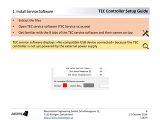
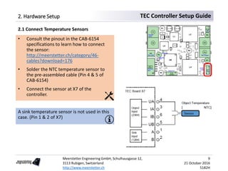
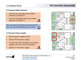
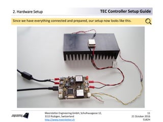
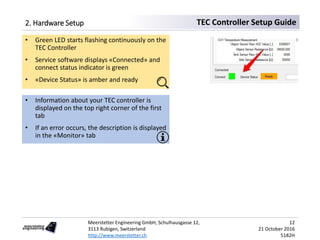
This document provides step-by-step instructions for setting up a Meerstetter Engineering TEC controller for the first time. The setup involves installing software, connecting hardware components including a Peltier element, temperature sensors, and power supply. The document then guides configuring default settings, measuring temperature, defining the Peltier element and temperature controller characteristics, and performing auto-tuning to keep an object at a constant temperature using the TEC controller.

![Meerstetter Engineering GmbH, Schulhausgasse 12,
3113 Rubigen, Switzerland
http://www.meerstetter.ch
17
21 October 2016
5182H
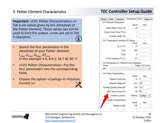
TEC Controller Setup Guide6. Temperature Controller
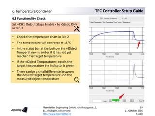
Set «Target Object Temp [°C]» at «CH1
Nominal Temperature» to 15
In «CH1 Modelization for Thermal Power
Regulation» the option «Peltier, Full Control»
is chosen. That means that the controller can
heat and cool the object using the Peltier
element.
Our goal is now to keep an object at a
constant temperature. First we set the
control parameters. Then we have to limit
the output of the TEC controller.
6.1 Target Object Temperature](https://image.slidesharecdn.com/tecsetupguide5182h-170217124353/85/Tec-setup-guide-5182H-17-320.jpg)
![Meerstetter Engineering GmbH, Schulhausgasse 12,
3113 Rubigen, Switzerland
http://www.meerstetter.ch
18
21 October 2016
5182H
TEC Controller Setup Guide6. Temperature Controller
• Set «CH1 Output Stage Control Input
Selection» to «Temperature Controller»
• Set «CH1 Output Stage Limits» & Error
thresholds for this example:
«Current Limitation [A]»: 4
«Voltage Limitation [V]»: 9.6
«Current Error Threshold [A]»: 4.8
«Voltage Error Threshold [V]»: 12
Error thresholds should be set approx. 20%
over the corresponding limits. An error is
generated if a value reaches the threshold.
Now we need to set the output limits for the
operation of the Peltier element.
Limits are set depending on the application.
However, usually the voltage limitation
should be set approx. 1 V over Umax of the
Peltier element.
6.2 Operation Limits](https://image.slidesharecdn.com/tecsetupguide5182h-170217124353/85/Tec-setup-guide-5182H-18-320.jpg)