1
System Software
by Leland L. Beck
chapter 1, pp.1-20.
Chap 1
2
Outline of Chapter 1
 System Software and Machine Architecture
 The Simplified Instructional Computer (SIC)
Chap 1
3
System Software vs. Machine Architecture
 Machine dependent
 The most important characteristic in which most
system software differ from application software
 e.g. assembler translate mnemonic instructions into
machine code
 e.g. compilers must generate machine language code
 Machine independent
 There are aspects of system software that do not directly
depend upon the type of computing system
 e.g. general design and logic of an assembler
 e.g. code optimization techniques
Chap 1
4
The Simplified Instructional Computer (SIC)
 SIC is a hypothetical computer that includes
the hardware features most often found on
real machines
 Two versions of SIC
 standard model
 extension version
Chap 1
5
SIC Machine Architecture (1/5)
 Memory
 215 bytes =32768 bytes in the computer memory
 15 address lines
 3 consecutive bytes form a word
 8-bit bytes
Chap 1
6
SIC Machine Architecture (1/5)
 Registers
There are 5 registers all of 24bits in length
Mnemonic Number Specialuse
A 0 Accumulator;usedforarithmeticoperations
X 1 Indexregister;usedforaddressing
L 2 Linkageregister;JSUB//storesthereturnaddress
PC 8 Programcounter
SW 9 Statusword,includingCC
Chap 1
7
SIC Machine Architecture (2/5)
 Data Formats
 Integers are stored as 24-bit binary numbers;
 2’s complement representation is used for
negative values
 8 bit ASCII code for characters
 No floating-point hardware
Chap 1
8
SIC Machine Architecture (2/5)
Instruction Formats
 All instructions are of 24bit format
 Addressing Modes
opcode (8) address (15)
x
Mode Indication Target address calculation
Direct x=0 TA=address
Indexed x=1 TA=address+(X)
Chap 1
9
SIC Machine Architecture (3/5)
 Instruction Set
 Data transfer group
 Arithmetic group
 Logical group of instruction
 Branch group
 Machine group
Chap 1
10
SIC Machine Architecture (3/5)
 Data transfer Instructions
LDA(00)-load data into accumulator
LDX(04)- load data into index register
LDL(08)-load data into linkage register
LDCH(50)-load char into accumulator
STA(0C)-store the contents of A into the
memory
STX(10)-store the contents of X into the
memory
STL(14)-store the contents of L into the
memory
STSW(E8)-store the contents of SW into the
Chap 1
11
SIC Machine Architecture (3/5)
 Arithmetic group of Instructions
 ADD(18)
 SUB(1C)
 MUL(20)
 DIV(34)
 All arithmetic operations involve register A and
a word in memory, with the result being left in
the register
Chap 1
12
SIC Machine Architecture (3/5)
Logical group of Instructions
 AND(40)
 OR(44)
Both involve register A and a word in memory,
with the result being left in the register
condition flag is not affected
COMP(28)
compares the value in register A(<,>,=) with a
word in memory, this instruction sets a condition
code CC to indicate the result
Chap 1
13
SIC Machine Architecture (4/5)
 Branch group of Instructions
 Conditional jump instructions
 Unconditional jump instructions
 Subroutine linkage
Chap 1
14
SIC Machine Architecture (4/5)
 Instruction Set
 Conditional jump instructions:
 JLT(38)
 JEQ(30)
 JGT(34)
 these instructions test the setting of CC
(<.=.>)and jump accordingly
Chap 1
15
SIC Machine Architecture (4/5)
 Instruction Set
 Uconditional jump instructions:
 J(3C)
 This instruction with out testing the setting of
CC , jumps directly to assigned memory
Chap 1
16
SIC Machine Architecture (4/5)
 Subroutine linkage:
 JSUB(48)
 JSUB jumps to the subroutine, placing the return address in
register L
 ( L  PC , PC  subroutine address)
 RSUB(4C)
 RSUB returns by jumping to the address contained in register
L
 ( PC  L )
Chap 1
17
SIC Machine Architecture (5/5)
 Input and Output
 Input and output are performed by transferring 1
byte at a time to or from the rightmost 8 bits of
register A
 The Test Device TD (E0) instruction tests whether
the addressed device is ready to send or receive a
byte of data
if CC=‘<‘ the device is ready to send or receive
if CC=‘=‘ the device is not ready to send or receive
Chap 1
18
SIC Machine Architecture (5/5)
 Input and Output
 Read Data RD(D8)
 Data from the device specified by the memory is
read into A lower order byte
 Write Data WD(DC)
 Data is sent to output device specified by the
memory
Chap 1
19
SIC Machine Architecture (5/5)
 Input and Output
 TIX(2C)
 Increments the content of X and compares its
content with memory
 Depending on the result the conditional flags are
updated
if (X) < (m) then CC = ‘<‘
if (X) = (m) then CC = ‘=‘
if (X) > (m) then CC = ‘>‘
Chap 1
20
SIC Machine Architecture (5/5)
 Machine group of instructions
 HIO(F4)
 To halt the I/O channel.
 Channel address is provided in A register
 SIO(F0)
 To start the I/O channel.
Chap 1
21
SIC/XE Machine Architecture (1/4)
 Memory
 Memory structure is same as that for SIC
 220 bytes in the computer memory
 This increase leads to a change in instruction
format and addressing modes.
 More Registers
Mnemonic Number Special use
B 3 Base register; used for addressing
S 4 General working register
T 5 General working register
F 6 Floating-point acumulator (48bits)
Chap 1
22
SIC/XE Machine Architecture (2/4)
 Data Formats
 Same data format as that of SIC
 Floating-point data type of 48 bits
 frac: 0~1
 exp: 0~2047
 S(0=+ve , 1=-ve)
the absolute value of the number is
frac*2(exp-1024)
exponent (11) fraction (36)
s
Chap 1
23
SIC/XE Machine Architecture (2/4)
 Instruction Formats
 The instruction format of SIC/XE is modified to
suit the changes made in the hardware such
as
 Enhancing the number of address lines
 Increasing the number of registers
 Providing floating point accumulator
Chap 1
24
SIC/XE Machine Architecture
 Instruction Formats
8
op
8 4 4
op r1 r2
Format 1 (1 byte)
Format 2 (2 bytes)
Formats 1 and 2 are instructions that do not reference memory at all
6 1 1 1 1 1 1 12
op n i x b p e disp
Format 3 (3 bytes)
6 1 1 1 1 1 1 20
op n i x b p e address
Format 4 (4 bytes)
Chap 1
25
SIC/XE Machine Architecture (2/4)
 The Format 3 and Format 4 instructions have
6 flag bits:-
n – indirect addressing
I – immediate addressing
x – indexed addressing
b – base relative
p – PC relative
e – (0 – Format 3 1 – Format 4)
Chap 1
26
SIC/XE Machine Architecture
 Addressing modes
 Base relative (n=1, i=1, b=1, p=0)
 Program-counter relative (n=1, i=1, b=0, p=1)
 Direct (n=1, i=1, b=0, p=0)
 Immediate (n=0, i=1, x=0)
 Indirect (n=1, i=0, x=0)
 Indexing (both n & i = 0 or 1, x=1)
 Extended (e=1)
Chap 1
27
SIC/XE Machine Architecture
 Base Relative Addressing Mode (STCH BUF,X)
n i x b p e
opcode 1 1 1 0 disp
n=1, i=1, b=1, p=0, TA=(B)+disp (0disp 4095)
 PC Relative Addressing Mode (J Next)(-ve=2’s
comp
n i x b p e
opcode 1 1 0 1 disp
n=1, i=1, b=0, p=1, TA=(PC)+disp (-2048disp 2047)
Chap 1
28
SIC/XE Machine Architecture
 Direct Addressing Mode
n i x b p e
opcode 1 1 0 0 disp
n=1, i=1, b=0, p=0, TA=disp (0disp 4095)
n i x b p e
opcode 1 1 1 0 0 disp
n=1, i=1, b=0, p=0, TA=(X)+disp
(with index addressing mode)
Chap 1
29
SIC/XE Machine Architecture
 Immediate Addressing Mode (ADD #30)
n i x b p e
opcode 0 1 0 disp
n=0, i=1, x=0, operand=disp
 Indirect Addressing Mode (ADD @2000)
n i x b p e
opcode 1 0 0 disp
n=1, i=0, x=0, TA=(disp)
Chap 1
30
SIC/XE Machine Architecture
 Simple Addressing Mode (LDA NUM)
n i x b p e
opcode 0 0 disp
i=0, n=0, TA=bpe+disp (SIC standard)
n i x b p e
opcode 1 1 disp
i=1, n=1, TA=disp (SIC/XE standard)
Chap 1
31
SIC/XE Machine Architecture (3/4)
 Addressing Modes
 Note: Indexing cannot be used with immediate or
indirect addressing modes
Mode Indication Target address calculation Example
Base relative b=1, p=0 TA=(B)+disp (0<=disp<=4095) LDA B, X
PC-relative b=0, p=1 TA=(PC)+disp (-2048<=disp<=2047) // -ve --> 2's comp
J next
Register ADDR S, A
Direct b=0, p=0 TA=disp (format 3) or address (format 4) ADD ALPHA
Indexed x=1 TA=TA+(X) LDA NUM, X
immediate addressing i=1, n=0 (TA) (ADD #30)
indirect addressing i=0, n=1 ((TA)) (ADD @020)
simple addressing i=0, n=0 SIC instruction (all end with 00)
i=1, n=1 SIC/XE instruction
Implied Addressing HIO, SIO, TIO
Example of SIC/XE instructions
and addressing modes
Chap 1
33
SIC Machine Architecture (3/5)
 Data transfer Instructions
LDB(68)-load data into BASE register
LDS(6E)- load data into S register
LPS(D0)-load processor status
LDT(04)-load data into T register
LDF(70)-load data into F register
STB-store the contents of B into the
memory
STS-store the contents of S into the
memory
STL(14)-store the contents of L into the
memory
STSW(E8)-store the contents of SW into the
memory
Chap 1
34
SIC/XE Machine Architecture (4/4)
 Instruction Set
 new registers: LDB,LDL,LDS, STB, etc.
 floating-point arithmetic: ADDF, SUBF, MULF, DIVF
 register move:data transfer from 1 reg to another reg RMO
S,A (SA)
 register-register arithmetic: ADDR, SUBR, MULR, DIVR
 Logical :
 COMPR A,S
 CLEAR X
 SHIFTL T,n
 SHIFTR T,n
Chap 1
35
SIC Programming Examples (Fig 1.2a)
To store 5 in ALPHA and z in C1
Chap 1
36
SIC/XE Programming Examples (Fig 1.2b)
Chap 1
37
SIC Programming Example (Fig 1.3a)
BETA=ALPHA+INCR-1 AND DELTA=GAMMA+INCR-1
Chap 1
38
SIC/XE Programming Example (Fig 1.3b)
Chap 1
39
SIC Programming Example (Fig 1.4a)
to copy one 11 byte char string to another
Chap 1
40
SIC/XE Programming Example (Fig 1.4b)
Chap 1
41
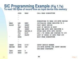
SIC Programming Example (Fig 1.5a)
GAMMA[I]=ALPHA[I]+BETA[I]
I=0 to 100
Chap 1
42
SIC/XE Programming Example (Fig 1.5b)
Chap 1
43
SIC Programming Example (Fig 1.6)
to read 1 byte of data from device F1 andcopy it to device 05
Chap 1
44
SIC Programming Example (Fig 1.7a)
To read 100 bytes of record from an input device into memory
Chap 1
45
SIC/XE Programming Example (Fig 1.7b)

system software.ppt

  • 1.
    1 System Software by LelandL. Beck chapter 1, pp.1-20.
  • 2.
    Chap 1 2 Outline ofChapter 1  System Software and Machine Architecture  The Simplified Instructional Computer (SIC)
  • 3.
    Chap 1 3 System Softwarevs. Machine Architecture  Machine dependent  The most important characteristic in which most system software differ from application software  e.g. assembler translate mnemonic instructions into machine code  e.g. compilers must generate machine language code  Machine independent  There are aspects of system software that do not directly depend upon the type of computing system  e.g. general design and logic of an assembler  e.g. code optimization techniques
  • 4.
    Chap 1 4 The SimplifiedInstructional Computer (SIC)  SIC is a hypothetical computer that includes the hardware features most often found on real machines  Two versions of SIC  standard model  extension version
  • 5.
    Chap 1 5 SIC MachineArchitecture (1/5)  Memory  215 bytes =32768 bytes in the computer memory  15 address lines  3 consecutive bytes form a word  8-bit bytes
  • 6.
    Chap 1 6 SIC MachineArchitecture (1/5)  Registers There are 5 registers all of 24bits in length Mnemonic Number Specialuse A 0 Accumulator;usedforarithmeticoperations X 1 Indexregister;usedforaddressing L 2 Linkageregister;JSUB//storesthereturnaddress PC 8 Programcounter SW 9 Statusword,includingCC
  • 7.
    Chap 1 7 SIC MachineArchitecture (2/5)  Data Formats  Integers are stored as 24-bit binary numbers;  2’s complement representation is used for negative values  8 bit ASCII code for characters  No floating-point hardware
  • 8.
    Chap 1 8 SIC MachineArchitecture (2/5) Instruction Formats  All instructions are of 24bit format  Addressing Modes opcode (8) address (15) x Mode Indication Target address calculation Direct x=0 TA=address Indexed x=1 TA=address+(X)
  • 9.
    Chap 1 9 SIC MachineArchitecture (3/5)  Instruction Set  Data transfer group  Arithmetic group  Logical group of instruction  Branch group  Machine group
  • 10.
    Chap 1 10 SIC MachineArchitecture (3/5)  Data transfer Instructions LDA(00)-load data into accumulator LDX(04)- load data into index register LDL(08)-load data into linkage register LDCH(50)-load char into accumulator STA(0C)-store the contents of A into the memory STX(10)-store the contents of X into the memory STL(14)-store the contents of L into the memory STSW(E8)-store the contents of SW into the
  • 11.
    Chap 1 11 SIC MachineArchitecture (3/5)  Arithmetic group of Instructions  ADD(18)  SUB(1C)  MUL(20)  DIV(34)  All arithmetic operations involve register A and a word in memory, with the result being left in the register
  • 12.
    Chap 1 12 SIC MachineArchitecture (3/5) Logical group of Instructions  AND(40)  OR(44) Both involve register A and a word in memory, with the result being left in the register condition flag is not affected COMP(28) compares the value in register A(<,>,=) with a word in memory, this instruction sets a condition code CC to indicate the result
  • 13.
    Chap 1 13 SIC MachineArchitecture (4/5)  Branch group of Instructions  Conditional jump instructions  Unconditional jump instructions  Subroutine linkage
  • 14.
    Chap 1 14 SIC MachineArchitecture (4/5)  Instruction Set  Conditional jump instructions:  JLT(38)  JEQ(30)  JGT(34)  these instructions test the setting of CC (<.=.>)and jump accordingly
  • 15.
    Chap 1 15 SIC MachineArchitecture (4/5)  Instruction Set  Uconditional jump instructions:  J(3C)  This instruction with out testing the setting of CC , jumps directly to assigned memory
  • 16.
    Chap 1 16 SIC MachineArchitecture (4/5)  Subroutine linkage:  JSUB(48)  JSUB jumps to the subroutine, placing the return address in register L  ( L  PC , PC  subroutine address)  RSUB(4C)  RSUB returns by jumping to the address contained in register L  ( PC  L )
  • 17.
    Chap 1 17 SIC MachineArchitecture (5/5)  Input and Output  Input and output are performed by transferring 1 byte at a time to or from the rightmost 8 bits of register A  The Test Device TD (E0) instruction tests whether the addressed device is ready to send or receive a byte of data if CC=‘<‘ the device is ready to send or receive if CC=‘=‘ the device is not ready to send or receive
  • 18.
    Chap 1 18 SIC MachineArchitecture (5/5)  Input and Output  Read Data RD(D8)  Data from the device specified by the memory is read into A lower order byte  Write Data WD(DC)  Data is sent to output device specified by the memory
  • 19.
    Chap 1 19 SIC MachineArchitecture (5/5)  Input and Output  TIX(2C)  Increments the content of X and compares its content with memory  Depending on the result the conditional flags are updated if (X) < (m) then CC = ‘<‘ if (X) = (m) then CC = ‘=‘ if (X) > (m) then CC = ‘>‘
  • 20.
    Chap 1 20 SIC MachineArchitecture (5/5)  Machine group of instructions  HIO(F4)  To halt the I/O channel.  Channel address is provided in A register  SIO(F0)  To start the I/O channel.
  • 21.
    Chap 1 21 SIC/XE MachineArchitecture (1/4)  Memory  Memory structure is same as that for SIC  220 bytes in the computer memory  This increase leads to a change in instruction format and addressing modes.  More Registers Mnemonic Number Special use B 3 Base register; used for addressing S 4 General working register T 5 General working register F 6 Floating-point acumulator (48bits)
  • 22.
    Chap 1 22 SIC/XE MachineArchitecture (2/4)  Data Formats  Same data format as that of SIC  Floating-point data type of 48 bits  frac: 0~1  exp: 0~2047  S(0=+ve , 1=-ve) the absolute value of the number is frac*2(exp-1024) exponent (11) fraction (36) s
  • 23.
    Chap 1 23 SIC/XE MachineArchitecture (2/4)  Instruction Formats  The instruction format of SIC/XE is modified to suit the changes made in the hardware such as  Enhancing the number of address lines  Increasing the number of registers  Providing floating point accumulator
  • 24.
    Chap 1 24 SIC/XE MachineArchitecture  Instruction Formats 8 op 8 4 4 op r1 r2 Format 1 (1 byte) Format 2 (2 bytes) Formats 1 and 2 are instructions that do not reference memory at all 6 1 1 1 1 1 1 12 op n i x b p e disp Format 3 (3 bytes) 6 1 1 1 1 1 1 20 op n i x b p e address Format 4 (4 bytes)
  • 25.
    Chap 1 25 SIC/XE MachineArchitecture (2/4)  The Format 3 and Format 4 instructions have 6 flag bits:- n – indirect addressing I – immediate addressing x – indexed addressing b – base relative p – PC relative e – (0 – Format 3 1 – Format 4)
  • 26.
    Chap 1 26 SIC/XE MachineArchitecture  Addressing modes  Base relative (n=1, i=1, b=1, p=0)  Program-counter relative (n=1, i=1, b=0, p=1)  Direct (n=1, i=1, b=0, p=0)  Immediate (n=0, i=1, x=0)  Indirect (n=1, i=0, x=0)  Indexing (both n & i = 0 or 1, x=1)  Extended (e=1)
  • 27.
    Chap 1 27 SIC/XE MachineArchitecture  Base Relative Addressing Mode (STCH BUF,X) n i x b p e opcode 1 1 1 0 disp n=1, i=1, b=1, p=0, TA=(B)+disp (0disp 4095)  PC Relative Addressing Mode (J Next)(-ve=2’s comp n i x b p e opcode 1 1 0 1 disp n=1, i=1, b=0, p=1, TA=(PC)+disp (-2048disp 2047)
  • 28.
    Chap 1 28 SIC/XE MachineArchitecture  Direct Addressing Mode n i x b p e opcode 1 1 0 0 disp n=1, i=1, b=0, p=0, TA=disp (0disp 4095) n i x b p e opcode 1 1 1 0 0 disp n=1, i=1, b=0, p=0, TA=(X)+disp (with index addressing mode)
  • 29.
    Chap 1 29 SIC/XE MachineArchitecture  Immediate Addressing Mode (ADD #30) n i x b p e opcode 0 1 0 disp n=0, i=1, x=0, operand=disp  Indirect Addressing Mode (ADD @2000) n i x b p e opcode 1 0 0 disp n=1, i=0, x=0, TA=(disp)
  • 30.
    Chap 1 30 SIC/XE MachineArchitecture  Simple Addressing Mode (LDA NUM) n i x b p e opcode 0 0 disp i=0, n=0, TA=bpe+disp (SIC standard) n i x b p e opcode 1 1 disp i=1, n=1, TA=disp (SIC/XE standard)
  • 31.
    Chap 1 31 SIC/XE MachineArchitecture (3/4)  Addressing Modes  Note: Indexing cannot be used with immediate or indirect addressing modes Mode Indication Target address calculation Example Base relative b=1, p=0 TA=(B)+disp (0<=disp<=4095) LDA B, X PC-relative b=0, p=1 TA=(PC)+disp (-2048<=disp<=2047) // -ve --> 2's comp J next Register ADDR S, A Direct b=0, p=0 TA=disp (format 3) or address (format 4) ADD ALPHA Indexed x=1 TA=TA+(X) LDA NUM, X immediate addressing i=1, n=0 (TA) (ADD #30) indirect addressing i=0, n=1 ((TA)) (ADD @020) simple addressing i=0, n=0 SIC instruction (all end with 00) i=1, n=1 SIC/XE instruction Implied Addressing HIO, SIO, TIO
  • 32.
    Example of SIC/XEinstructions and addressing modes
  • 33.
    Chap 1 33 SIC MachineArchitecture (3/5)  Data transfer Instructions LDB(68)-load data into BASE register LDS(6E)- load data into S register LPS(D0)-load processor status LDT(04)-load data into T register LDF(70)-load data into F register STB-store the contents of B into the memory STS-store the contents of S into the memory STL(14)-store the contents of L into the memory STSW(E8)-store the contents of SW into the memory
  • 34.
    Chap 1 34 SIC/XE MachineArchitecture (4/4)  Instruction Set  new registers: LDB,LDL,LDS, STB, etc.  floating-point arithmetic: ADDF, SUBF, MULF, DIVF  register move:data transfer from 1 reg to another reg RMO S,A (SA)  register-register arithmetic: ADDR, SUBR, MULR, DIVR  Logical :  COMPR A,S  CLEAR X  SHIFTL T,n  SHIFTR T,n
  • 35.
    Chap 1 35 SIC ProgrammingExamples (Fig 1.2a) To store 5 in ALPHA and z in C1
  • 36.
    Chap 1 36 SIC/XE ProgrammingExamples (Fig 1.2b)
  • 37.
    Chap 1 37 SIC ProgrammingExample (Fig 1.3a) BETA=ALPHA+INCR-1 AND DELTA=GAMMA+INCR-1
  • 38.
    Chap 1 38 SIC/XE ProgrammingExample (Fig 1.3b)
  • 39.
    Chap 1 39 SIC ProgrammingExample (Fig 1.4a) to copy one 11 byte char string to another
  • 40.
    Chap 1 40 SIC/XE ProgrammingExample (Fig 1.4b)
  • 41.
    Chap 1 41 SIC ProgrammingExample (Fig 1.5a) GAMMA[I]=ALPHA[I]+BETA[I] I=0 to 100
  • 42.
    Chap 1 42 SIC/XE ProgrammingExample (Fig 1.5b)
  • 43.
    Chap 1 43 SIC ProgrammingExample (Fig 1.6) to read 1 byte of data from device F1 andcopy it to device 05
  • 44.
    Chap 1 44 SIC ProgrammingExample (Fig 1.7a) To read 100 bytes of record from an input device into memory
  • 45.
    Chap 1 45 SIC/XE ProgrammingExample (Fig 1.7b)