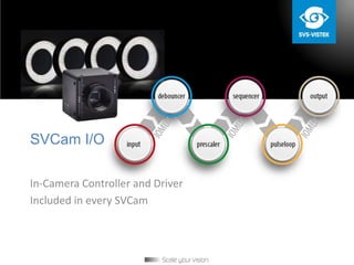
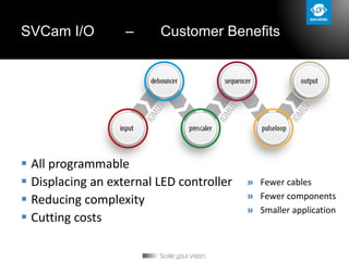
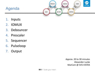
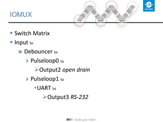
SVCam I/O
In-Camera Controller and Driver
Included in every SVCam
SVCam I/O
 Versatile inputs
» Trigger
signal
handling
» Generating
multiple signals
 Open drain outputs
SVCam I/O – Customer Benefits
 All programmable
 Displacing an external LED controller
 Reducing complexity
 Cutting costs
» Fewer cables
» Fewer components
» Smaller application
Agenda
1. Inputs
2. IOMUX
3. Debouncer
4. Prescaler
5. Sequencer
6. Pulseloop
7. Output
Approx. 20 to 30 minutes
Alexander Lucke
MarCom @ SVS-VISTEK
Input
 4 inputs
» Triggers
› Voltage up to 24 V
 Signals
» RS-232
By the way:
Opto isolator
For new EXO & SHR series
IOMUX
Switch matrix
Combining modules
 Input to
» Debouncer to
› … to
IOMUX
 Switch Matrix
 Input to
» Debouncer to
› Pulseloop0 to
Output2 open drain
› Pulseloop1 to
•UART to
Output3 RS-232
by the way: Inverter and set-to-one
 Before and after every IOMUX module
 Invert signal
» Trigger interpretation can
also be inverted
 Set signal to „1“
» Just turn the signal ON
» or turn it OFF by inverting it at the same time
Debouncer
 Eliminates „ringing“
» Glitches: spikes, overshoots
1. Masking the input for a period of
time
2. Comparing the signal after the
period
Prescaler
 Masking every 2nd, 3rd, 4th, and so on
by the way: high low trigger
Schmitt Trigger
Programmable values that
have to be crossed for a
trigger interpretation true
Sequencer
 One trigger signal results in:
» Up to 16 intervals with individual:
› Total length
› Exposure time
› PWM frequency
› Up to four strobe outputs with individual
•Intensity
•duration
Sequencer
 One trigger signal:
by the way: PWM
Pulse Width Modulation
Integrated in the Sequencer
 regulate the intensity of an LED light
» Extend LED life cycle
 Set base frequency period length
» for each sequencer interval
 Set duty cycle Δ in %
» for each sequencer output
by the way: PWM
25 % intensity
50 % intensity
75 % intensity
Pulseloop
 Four individual pulse generators
» Set delay and duration time
Pulseloop
 Four individual pulse generators
» Set number of loops
An individual PWM
Pulseloop
 Camera cascade
» Exposure internal cam1
» Exposure external cam2
» Trigger cam3
Pulseloop
 Wait for second shoot
After first aquisition software demands a second exposure
Pulseloop
or simple:
Exposure and Light …
Output
 Up to four open drain outputs
» 0.7 A permanent
» up to 3 A over 40 ms
 Signals
» RS-232
MOSFET transistors
Output
SVCam I/O – Customer Benefits
 Eliminates the need for an external controller
 Simplifies cabling
 Reduces costs
 Rises value of ownership of an SVCam
Thank you
Alexander Lucke
MarCom @ SVS-VISTEK

SVCam I/O modules – the camera as an IO controller

  • 1.
    SVCam I/O In-Camera Controllerand Driver Included in every SVCam
  • 2.
    SVCam I/O  Versatileinputs » Trigger signal handling » Generating multiple signals  Open drain outputs
  • 3.
    SVCam I/O –Customer Benefits  All programmable  Displacing an external LED controller  Reducing complexity  Cutting costs » Fewer cables » Fewer components » Smaller application
  • 4.
    Agenda 1. Inputs 2. IOMUX 3.Debouncer 4. Prescaler 5. Sequencer 6. Pulseloop 7. Output Approx. 20 to 30 minutes Alexander Lucke MarCom @ SVS-VISTEK
  • 5.
    Input  4 inputs »Triggers › Voltage up to 24 V  Signals » RS-232 By the way: Opto isolator For new EXO & SHR series
  • 6.
    IOMUX Switch matrix Combining modules Input to » Debouncer to › … to
  • 7.
    IOMUX  Switch Matrix Input to » Debouncer to › Pulseloop0 to Output2 open drain › Pulseloop1 to •UART to Output3 RS-232
  • 8.
    by the way:Inverter and set-to-one  Before and after every IOMUX module  Invert signal » Trigger interpretation can also be inverted  Set signal to „1“ » Just turn the signal ON » or turn it OFF by inverting it at the same time
  • 9.
    Debouncer  Eliminates „ringing“ »Glitches: spikes, overshoots 1. Masking the input for a period of time 2. Comparing the signal after the period
  • 10.
    Prescaler  Masking every2nd, 3rd, 4th, and so on
  • 11.
    by the way:high low trigger Schmitt Trigger Programmable values that have to be crossed for a trigger interpretation true
  • 12.
    Sequencer  One triggersignal results in: » Up to 16 intervals with individual: › Total length › Exposure time › PWM frequency › Up to four strobe outputs with individual •Intensity •duration
  • 13.
  • 14.
    by the way:PWM Pulse Width Modulation Integrated in the Sequencer  regulate the intensity of an LED light » Extend LED life cycle  Set base frequency period length » for each sequencer interval  Set duty cycle Δ in % » for each sequencer output
  • 15.
    by the way:PWM 25 % intensity 50 % intensity 75 % intensity
  • 16.
    Pulseloop  Four individualpulse generators » Set delay and duration time
  • 17.
    Pulseloop  Four individualpulse generators » Set number of loops An individual PWM
  • 18.
    Pulseloop  Camera cascade »Exposure internal cam1 » Exposure external cam2 » Trigger cam3
  • 19.
    Pulseloop  Wait forsecond shoot After first aquisition software demands a second exposure
  • 20.
  • 21.
    Output  Up tofour open drain outputs » 0.7 A permanent » up to 3 A over 40 ms  Signals » RS-232 MOSFET transistors
  • 22.
  • 23.
    SVCam I/O –Customer Benefits  Eliminates the need for an external controller  Simplifies cabling  Reduces costs  Rises value of ownership of an SVCam
  • 24.