Download as PDF, PPTX
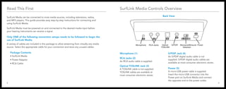
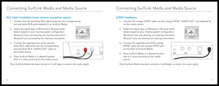

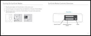
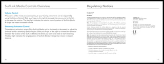


This document provides instructions for connecting and using the SurfLink Media device to stream audio from various media sources to hearing aids. It includes details on the connection options using included cables like RCA, S/PDIF, and TOSLINK, as well as controls on the device for volume adjustment and streaming activation range. Setup requires selecting the appropriate cable, powering on the device, and choosing mono or binaural audio based on the number of hearing aids used.