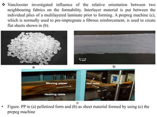
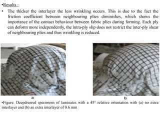
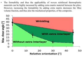
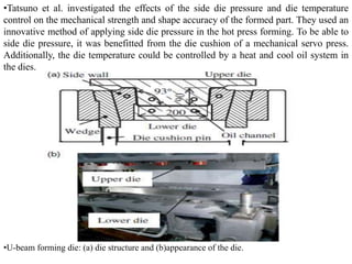
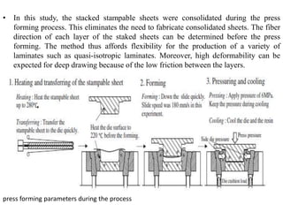
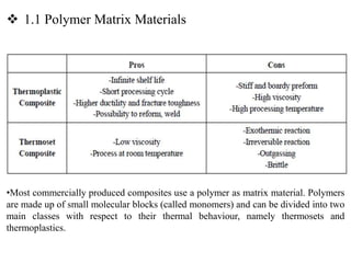
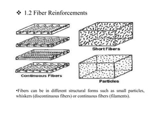
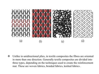
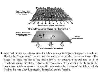
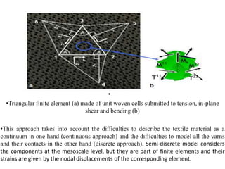
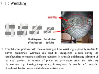
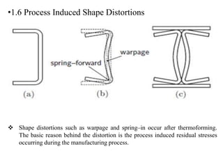
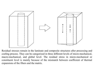
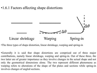
NUMERICAL AND EXPERIMENTAL ANALYSIS
OF THERMO-STAMPING PROCESS APPLIED TO
WOVEN FABRIC REINFORCED
THERMOPLASTIC COMPOSITES
YILDIRIM BEYAZIT ÜNİVERSİTESİ
Supervisor : Prof. Dr. FAHRETTİN ÖZTÜRK
Prepared by Halil YILDIRIM
1. INTRODUCTION
•Use of fibre-reinforced polymer composite materials in the A380
 1.1 Polymer Matrix Materials
•Most commercially produced composites use a polymer as matrix material. Polymers
are made up of small molecular blocks (called monomers) and can be divided into two
main classes with respect to their thermal behaviour, namely thermosets and
thermoplastics.
 1.2 Fiber Reinforcements
•Fibers can be in different structural forms such as small particles,
whiskers (discontinuous fibers) or continuous fibers (filaments).
 Unlike in unidirectional plies, in textile composites the fibres are oriented
in more than one direction. Generally textile composites are divided into
three types, depending on the techniques used to create the reinforcement
mat. These are woven fabrics, braided fabrics, knitted fabrics .
•Cloth Versus Unidirectional
• Advantages of cloth :
• Drapes very well
• Easier to layup over complicated geometry
• Strength in two directions
• Bonds slightly better than uni
• Disadvantages of cloth :
• More expensive than uni
• Lower properties due to the fact fibers have to travel out-
of-plane (over and under) due to the weaving process
• Advantages of unidirectional :
• Better directional in-plane properties
• Less expensive than cloth
• Can easily tailor properties (i.e. strength, stiffness)
in the needed direction
• Disadvantages of unidirectional :
• Hard to lay up over difficult geometry or complex
curvature
• Requires careful planning to handle bearing loads
• May require longer lay up time to achieve desired
thicknesses (uni is generally thinner than cloth)
 Woven fabrics are the most commonly used form. The textile
consists of two interlaced yarn components, known as warp and
weft, and is produced mainly by the multiple warp weaving
method.
•Common Lay-up Terms and Conditions
 Symmetry: A laminate is symmetric when the plies above the mid-plane are a
mirror image of those below the mid-plane. Symmetrical lay-ups help to avoid
thermal twisting of parts as they cool down after curing.
 Balance: A laminate is balanced when it has equal numbers of – and + angled plies.
 Quasi-isotropic:
• Isotropic means having the same properties in all directions.
• Quasi-isotropic means having isotropic properties in-plane. A quasi-isotropic part
has either randomly oriented fiber in all directions, or has fibers oriented such that
equal strength is developed all around the plane of the part.
• Generally, a quasi-isotropic laminate made from woven fabric has plies oriented at
0º, 90º +45º and –45º, with at least 12.5% of the plies in each of these four
directions.
• Quasi-isotropic properties can also be achieved with 0º, 60º and 120º oriented
unidirectional plies.
• 1.3 Deformation Mechanisms of Textile Reinforcement
 Various deformation mechanisms can occur during forming of a sheet of textile
composite material. These deformations can be classified according to the length
scale over which they occur. These scales are referred as macroscale, mesoscale
and microscale.
• Figure 3: Macro-scale deformations : a) shear, b) tension, c) ply-ply
friction, d) bending, e) compaction
 The macroscopic drape behaviour is governed by deformation
mechanisms at lower scales: meso-scale interactions (yarn-yarn or yarn-
resin) or micro-interactions (fibre-fibre or fibre-resin).
 Intra‐ply shear is considered to be the primary deformation mechanism
during forming of textile reinforcements to 3D shapes. This type of
deformation is characterized by a change of fibre orientation, due to rotation
of the yarns at their crossovers.
•Experimental Fabric Characterization Methods
•Testing mechanism of in-plane shear behaviour for fabric materials [Shuai Chen Thesis]
•Standard material testing methods are necessary for researchers to understand the
formability of the material, the effects of process variables on formability, and to
provide input data and validation data for numerical simulations. As shearing is the
major forming mechanism for forming of double curved geometries with woven fabrics
it has been the most intensively studied forming behaviour. Two methods to describe
the intra-ply shearing behaviour are widely used: picture frame and bias extension tests,
both showing benefits and disadvantages.
• .
•Picture Frame Test
• Geometrical configuration of a PF test: (a) Geometry of the frame; (b) Specimen
mounted in the fixture [Armin Rashidi Mehrabadi Thesis]
 For picture frame tests a cross shaped test sample is mounted on a square frame
hinged in the corners. The picture frame is extended subsequently on a tensile
testing machine. Shear force vs. shear angle curves can be calculated from the
force–displacement curves.
•Geometrical configuration of a BE test
• The bias extension (BE) test is an alternative to the PF test, consisting of a
rectangular sample such that the weft and warp yarns are originally oriented at
45° to the orientation of the applied tension. The initial length of the specimen
must be more than twice the width of the specimen in a BE test . [Armin Rashidi
Mehrabadi Thesis]
• 1.4 Thermoforming of Pre-impregnated Thermoplastics
•1.5 Textile draping simulation
•This section describes the different simulation approaches for draping of textile
composite sheets into complex products. The aim of these simulations is to evaluate, on
the one hand, whether a shape can be formed without defects. On the other hand, if the
forming goes well, the local deformations that happen during forming should be known
since they determine the mechanical response of the formed product.
 1.5.1 Kinematic mapping approach
•The kinematic mapping model is based on the assumption that deformation is restricted
to in‐plane shear. It is also called ‘pin‐jointed net’ (PJN), because the yarns are
considered inextensible and pin‐jointed at crossover points with no relative slippage.
The fabric behaves as a ‘fishnet’ and is mapped accordingly onto the surface of the
forming tool. Hereby only geometric information about the draping process is provided.
Stresses or applied forces are not considered.
•
•The alternative to the mapping approach is a mechanical model. Traditional mechanical
forming simulations are performed using the finite element (FE) method. Three
mechanical approaches can be found in the literature, namely a discrete, a continuous and
a semi‐discrete approach. All these approaches study the phenomena at the macro‐scale
of the fabric composite. These macro‐scale models require the input of correct material
behaviour of the fabric, which is performed via textile testing (picture frame, bias
extension, pull‐out, etc…).
• Principle of the discrete mesoscopic modeling using a combination of 1-D and 2-D elements
 In a discrete approach beams or trusses represent the yarns and the interactions
between the yarns are modelled using springs. The major benefit of this approach is
that the yarn directions are tracked “naturally” since they coincide with the orientation
of the beams or trusses. The major pitfall, however, is the relatively high
computational cost needed to perform a simulation.
•
 A second possibility is to consider the fabric as an anisotropic homogeneous medium.
Hereby the fibrous reinforcement and the matrix are considered as a continuum. The
benefit of these models is the possibility to be integrated in standard shell or
membrane elements. Though, due to the complexity of the draping mechanisms, the
continuum needs to convey the specific mechanical behaviour of the fabric, which
implies the yarn directions need to be tracked during forming.
•
•Triangular finite element (a) made of unit woven cells submitted to tension, in-plane
shear and bending (b)
•This approach takes into account the difficulties to describe the textile material as a
continuum in one hand (continuous approach) and the difficulties to model all the yarns
and their contacts in the other hand (discrete approach). Semi‐discrete model considers
the components at the mesoscale level, but they are part of finite elements and their
strains are given by the nodal displacements of the corresponding element.
• 1.5 Wrinkling
 A well-known problem with thermoforming is fibre wrinkling, especially on double
curved geometries. Wrinkles can lead to unexpected failures during the
manufacturing, or cause a significant reduction in strength and damage tolerance of
the final product. A number of processing parameters affect the wrinkling
phenomenon, e.g., forming temperature, forming rate, the number of composite
plies, blank holder pressure and fabric orientation, etc.
•1.6 Process Induced Shape Distortions
 Shape distortions such as warpage and spring–in occur after thermoforming.
The basic reason behind the distortion is the process induced residual stresses
occurring during the manufacturing process.
Residual stresses remain in the laminate and composite structures after processing and
cooling process. They can be categorized in three different levels of micro-mechanical,
macro-mechanical, and global level. The residual stress in micro-mechanical or
constituent level is mainly because of the mismatch between coefficient of thermal
expansions of the fibers and the matrix.
•1.6.1 Factors affecting shape distortions
•The three types of shape distortion, linear shrinkage, warping and spring-in
•Generally it is said that shape distortions are comprised out of three major
contributions, namely linear shrinkage, warping and spring-in. Out of these three, the
two latter are of greater importance as they involve changes in the actual shape and not
only the geometrical dimensions alone. The two represent different phenomena as
warping refers to alterations of the shape of flat plates and sections while spring-in
involves changes of angled sections.
•Papers about Shape Distortion
 Beyong Sam Kim et al. [25] investigated the dimensional stability of V shaped
composite parts made from unidirectional polyamide-12/carbon fibre
commingled yarn.
• It was implemented anisotropic thermoviscoelastic material model in a FEA
solver for different cooling cycles.
• In the experimental study, the laminates, with stacking sequences of [08], [908]
and [904/04], were used.
• To manufacture the laminates, the mould containing the fabric plies was heated from room
temperature to 220 C, held at this temperature for 10 min, and finally cooled back to room
temperature.
• During the consolidation and cooling stages, a pressure of 15 bars was applied to the material.
• Both balanced and slightly unbalanced cooling conditions were applied, with a maximum
cooling rate of 10 C/min.
• Results :
• The angles predicted by the present thermoviscoelastic approach are similar to those
predicted by the thermoelastic approach in the literature. It seems that at these cooling rates in
this semi-crystalline matrix, the effect of viscoelastic relaxation during cooling is relatively
small.
• Low levels of stresses were obtained in the [908] and [08] parts, whereas the significant
stresses was obtained in the [904/04] part.
• The [08] laminate showed the largest deviation from the 900
angle of the mould, whereas the
[904/04] stacking sequence led to the highest curvature of the side planes.
• The differences in angle and curvature between parts cooled under balanced and unbalanced
conditions were found to be small. This is because the difference in temperature between the
upper and lower surfaces of the laminate during cooling was relatively small.
 Vanclooster investigated influence of the relative orientation between two
neighbouring fabrics on the formability. Interlayer material is put between the
individual plies of a multilayered laminate prior to forming. A prepreg machine (c),
which is normally used to pre‐impregnate a fibrous reinforcement, is used to create
flat sheets shown in (b).
• Figure. PP in (a) pelletized form and (b) as sheet material formed by using (c) the
prepeg machine
•Results :
• The thicker the interlayer the less wrinkling occurs. This is due to the fact the
friction coefficient between neighbouring plies diminishes, which shows the
importance of the contact behaviour between fabric plies during forming. Each ply
can deform more independently, the intra‐ply slip does not restrict the inter‐ply shear
of neighbouring plies and thus wrinkling is reduced.
•Figure. Deepdrawed specimens of laminates with a 45° relative orientation with (a) no extra
interlayer and (b) an extra interlayer of 0.6 mm
• The formability and thus the applicability of woven reinforced thermoplastic
materials can be highly increased by adding extra matrix material between the plies.
However, increasing the formability by adding extra matrix decreases the fibre
volume fraction, and thus also the mechanical properties, of the composite.
•Figure. The increase of the maximum shear angle when using an extra interlayer
•Tatsuno et al. investigated the effects of the side die pressure and die temperature
control on the mechanical strength and shape accuracy of the formed part. They used an
innovative method of applying side die pressure in the hot press forming. To be able to
side die pressure, it was benefitted from the die cushion of a mechanical servo press.
Additionally, the die temperature could be controlled by a heat and cool oil system in
the dies.
•U-beam forming die: (a) die structure and (b)appearance of the die.
• In this study, the stacked stampable sheets were consolidated during the press
forming process. This eliminates the need to fabricate consolidated sheets. The fiber
direction of each layer of the staked sheets can be determined before the press
forming. The method thus affords flexibility for the production of a variety of
laminates such as quasi-isotropic laminates. Moreover, high deformability can be
expected for deep drawing because of the low friction between the layers.
press forming parameters during the process

sunum.pptx

  • 1.
    NUMERICAL AND EXPERIMENTALANALYSIS OF THERMO-STAMPING PROCESS APPLIED TO WOVEN FABRIC REINFORCED THERMOPLASTIC COMPOSITES YILDIRIM BEYAZIT ÜNİVERSİTESİ Supervisor : Prof. Dr. FAHRETTİN ÖZTÜRK Prepared by Halil YILDIRIM
  • 2.
    1. INTRODUCTION •Use offibre-reinforced polymer composite materials in the A380
  • 3.
     1.1 PolymerMatrix Materials •Most commercially produced composites use a polymer as matrix material. Polymers are made up of small molecular blocks (called monomers) and can be divided into two main classes with respect to their thermal behaviour, namely thermosets and thermoplastics.
  • 4.
     1.2 FiberReinforcements •Fibers can be in different structural forms such as small particles, whiskers (discontinuous fibers) or continuous fibers (filaments).
  • 5.
     Unlike inunidirectional plies, in textile composites the fibres are oriented in more than one direction. Generally textile composites are divided into three types, depending on the techniques used to create the reinforcement mat. These are woven fabrics, braided fabrics, knitted fabrics .
  • 6.
    •Cloth Versus Unidirectional •Advantages of cloth : • Drapes very well • Easier to layup over complicated geometry • Strength in two directions • Bonds slightly better than uni • Disadvantages of cloth : • More expensive than uni • Lower properties due to the fact fibers have to travel out- of-plane (over and under) due to the weaving process
  • 7.
    • Advantages ofunidirectional : • Better directional in-plane properties • Less expensive than cloth • Can easily tailor properties (i.e. strength, stiffness) in the needed direction • Disadvantages of unidirectional : • Hard to lay up over difficult geometry or complex curvature • Requires careful planning to handle bearing loads • May require longer lay up time to achieve desired thicknesses (uni is generally thinner than cloth)
  • 8.
     Woven fabricsare the most commonly used form. The textile consists of two interlaced yarn components, known as warp and weft, and is produced mainly by the multiple warp weaving method.
  • 9.
    •Common Lay-up Termsand Conditions  Symmetry: A laminate is symmetric when the plies above the mid-plane are a mirror image of those below the mid-plane. Symmetrical lay-ups help to avoid thermal twisting of parts as they cool down after curing.  Balance: A laminate is balanced when it has equal numbers of – and + angled plies.
  • 10.
     Quasi-isotropic: • Isotropicmeans having the same properties in all directions. • Quasi-isotropic means having isotropic properties in-plane. A quasi-isotropic part has either randomly oriented fiber in all directions, or has fibers oriented such that equal strength is developed all around the plane of the part. • Generally, a quasi-isotropic laminate made from woven fabric has plies oriented at 0º, 90º +45º and –45º, with at least 12.5% of the plies in each of these four directions. • Quasi-isotropic properties can also be achieved with 0º, 60º and 120º oriented unidirectional plies.
  • 11.
    • 1.3 DeformationMechanisms of Textile Reinforcement  Various deformation mechanisms can occur during forming of a sheet of textile composite material. These deformations can be classified according to the length scale over which they occur. These scales are referred as macroscale, mesoscale and microscale.
  • 12.
    • Figure 3:Macro-scale deformations : a) shear, b) tension, c) ply-ply friction, d) bending, e) compaction  The macroscopic drape behaviour is governed by deformation mechanisms at lower scales: meso-scale interactions (yarn-yarn or yarn- resin) or micro-interactions (fibre-fibre or fibre-resin).
  • 13.
     Intra‐ply shearis considered to be the primary deformation mechanism during forming of textile reinforcements to 3D shapes. This type of deformation is characterized by a change of fibre orientation, due to rotation of the yarns at their crossovers.
  • 14.
    •Experimental Fabric CharacterizationMethods •Testing mechanism of in-plane shear behaviour for fabric materials [Shuai Chen Thesis] •Standard material testing methods are necessary for researchers to understand the formability of the material, the effects of process variables on formability, and to provide input data and validation data for numerical simulations. As shearing is the major forming mechanism for forming of double curved geometries with woven fabrics it has been the most intensively studied forming behaviour. Two methods to describe the intra-ply shearing behaviour are widely used: picture frame and bias extension tests, both showing benefits and disadvantages. • .
  • 15.
    •Picture Frame Test •Geometrical configuration of a PF test: (a) Geometry of the frame; (b) Specimen mounted in the fixture [Armin Rashidi Mehrabadi Thesis]  For picture frame tests a cross shaped test sample is mounted on a square frame hinged in the corners. The picture frame is extended subsequently on a tensile testing machine. Shear force vs. shear angle curves can be calculated from the force–displacement curves.
  • 16.
    •Geometrical configuration ofa BE test • The bias extension (BE) test is an alternative to the PF test, consisting of a rectangular sample such that the weft and warp yarns are originally oriented at 45° to the orientation of the applied tension. The initial length of the specimen must be more than twice the width of the specimen in a BE test . [Armin Rashidi Mehrabadi Thesis]
  • 17.
    • 1.4 Thermoformingof Pre-impregnated Thermoplastics
  • 18.
    •1.5 Textile drapingsimulation •This section describes the different simulation approaches for draping of textile composite sheets into complex products. The aim of these simulations is to evaluate, on the one hand, whether a shape can be formed without defects. On the other hand, if the forming goes well, the local deformations that happen during forming should be known since they determine the mechanical response of the formed product.
  • 19.
     1.5.1 Kinematicmapping approach •The kinematic mapping model is based on the assumption that deformation is restricted to in‐plane shear. It is also called ‘pin‐jointed net’ (PJN), because the yarns are considered inextensible and pin‐jointed at crossover points with no relative slippage. The fabric behaves as a ‘fishnet’ and is mapped accordingly onto the surface of the forming tool. Hereby only geometric information about the draping process is provided. Stresses or applied forces are not considered.
  • 20.
    • •The alternative tothe mapping approach is a mechanical model. Traditional mechanical forming simulations are performed using the finite element (FE) method. Three mechanical approaches can be found in the literature, namely a discrete, a continuous and a semi‐discrete approach. All these approaches study the phenomena at the macro‐scale of the fabric composite. These macro‐scale models require the input of correct material behaviour of the fabric, which is performed via textile testing (picture frame, bias extension, pull‐out, etc…).
  • 21.
    • Principle ofthe discrete mesoscopic modeling using a combination of 1-D and 2-D elements  In a discrete approach beams or trusses represent the yarns and the interactions between the yarns are modelled using springs. The major benefit of this approach is that the yarn directions are tracked “naturally” since they coincide with the orientation of the beams or trusses. The major pitfall, however, is the relatively high computational cost needed to perform a simulation.
  • 22.
    •  A secondpossibility is to consider the fabric as an anisotropic homogeneous medium. Hereby the fibrous reinforcement and the matrix are considered as a continuum. The benefit of these models is the possibility to be integrated in standard shell or membrane elements. Though, due to the complexity of the draping mechanisms, the continuum needs to convey the specific mechanical behaviour of the fabric, which implies the yarn directions need to be tracked during forming.
  • 23.
    • •Triangular finite element(a) made of unit woven cells submitted to tension, in-plane shear and bending (b) •This approach takes into account the difficulties to describe the textile material as a continuum in one hand (continuous approach) and the difficulties to model all the yarns and their contacts in the other hand (discrete approach). Semi‐discrete model considers the components at the mesoscale level, but they are part of finite elements and their strains are given by the nodal displacements of the corresponding element.
  • 24.
    • 1.5 Wrinkling A well-known problem with thermoforming is fibre wrinkling, especially on double curved geometries. Wrinkles can lead to unexpected failures during the manufacturing, or cause a significant reduction in strength and damage tolerance of the final product. A number of processing parameters affect the wrinkling phenomenon, e.g., forming temperature, forming rate, the number of composite plies, blank holder pressure and fabric orientation, etc.
  • 25.
    •1.6 Process InducedShape Distortions  Shape distortions such as warpage and spring–in occur after thermoforming. The basic reason behind the distortion is the process induced residual stresses occurring during the manufacturing process.
  • 26.
    Residual stresses remainin the laminate and composite structures after processing and cooling process. They can be categorized in three different levels of micro-mechanical, macro-mechanical, and global level. The residual stress in micro-mechanical or constituent level is mainly because of the mismatch between coefficient of thermal expansions of the fibers and the matrix.
  • 27.
    •1.6.1 Factors affectingshape distortions •The three types of shape distortion, linear shrinkage, warping and spring-in •Generally it is said that shape distortions are comprised out of three major contributions, namely linear shrinkage, warping and spring-in. Out of these three, the two latter are of greater importance as they involve changes in the actual shape and not only the geometrical dimensions alone. The two represent different phenomena as warping refers to alterations of the shape of flat plates and sections while spring-in involves changes of angled sections.
  • 28.
    •Papers about ShapeDistortion  Beyong Sam Kim et al. [25] investigated the dimensional stability of V shaped composite parts made from unidirectional polyamide-12/carbon fibre commingled yarn. • It was implemented anisotropic thermoviscoelastic material model in a FEA solver for different cooling cycles. • In the experimental study, the laminates, with stacking sequences of [08], [908] and [904/04], were used.
  • 29.
    • To manufacturethe laminates, the mould containing the fabric plies was heated from room temperature to 220 C, held at this temperature for 10 min, and finally cooled back to room temperature. • During the consolidation and cooling stages, a pressure of 15 bars was applied to the material. • Both balanced and slightly unbalanced cooling conditions were applied, with a maximum cooling rate of 10 C/min. • Results : • The angles predicted by the present thermoviscoelastic approach are similar to those predicted by the thermoelastic approach in the literature. It seems that at these cooling rates in this semi-crystalline matrix, the effect of viscoelastic relaxation during cooling is relatively small. • Low levels of stresses were obtained in the [908] and [08] parts, whereas the significant stresses was obtained in the [904/04] part. • The [08] laminate showed the largest deviation from the 900 angle of the mould, whereas the [904/04] stacking sequence led to the highest curvature of the side planes. • The differences in angle and curvature between parts cooled under balanced and unbalanced conditions were found to be small. This is because the difference in temperature between the upper and lower surfaces of the laminate during cooling was relatively small.
  • 30.
     Vanclooster investigatedinfluence of the relative orientation between two neighbouring fabrics on the formability. Interlayer material is put between the individual plies of a multilayered laminate prior to forming. A prepreg machine (c), which is normally used to pre‐impregnate a fibrous reinforcement, is used to create flat sheets shown in (b). • Figure. PP in (a) pelletized form and (b) as sheet material formed by using (c) the prepeg machine
  • 31.
    •Results : • Thethicker the interlayer the less wrinkling occurs. This is due to the fact the friction coefficient between neighbouring plies diminishes, which shows the importance of the contact behaviour between fabric plies during forming. Each ply can deform more independently, the intra‐ply slip does not restrict the inter‐ply shear of neighbouring plies and thus wrinkling is reduced. •Figure. Deepdrawed specimens of laminates with a 45° relative orientation with (a) no extra interlayer and (b) an extra interlayer of 0.6 mm
  • 32.
    • The formabilityand thus the applicability of woven reinforced thermoplastic materials can be highly increased by adding extra matrix material between the plies. However, increasing the formability by adding extra matrix decreases the fibre volume fraction, and thus also the mechanical properties, of the composite. •Figure. The increase of the maximum shear angle when using an extra interlayer
  • 33.
    •Tatsuno et al.investigated the effects of the side die pressure and die temperature control on the mechanical strength and shape accuracy of the formed part. They used an innovative method of applying side die pressure in the hot press forming. To be able to side die pressure, it was benefitted from the die cushion of a mechanical servo press. Additionally, the die temperature could be controlled by a heat and cool oil system in the dies. •U-beam forming die: (a) die structure and (b)appearance of the die.
  • 34.
    • In thisstudy, the stacked stampable sheets were consolidated during the press forming process. This eliminates the need to fabricate consolidated sheets. The fiber direction of each layer of the staked sheets can be determined before the press forming. The method thus affords flexibility for the production of a variety of laminates such as quasi-isotropic laminates. Moreover, high deformability can be expected for deep drawing because of the low friction between the layers. press forming parameters during the process

Editor's Notes

  • #3 A composite is a material composed of two or more individual materials. In most cases one of the constituents acts as reinforcement, having a high strength and stiffness, but lacking structural integrity. This reinforcing material is then embedded in matrix material, which often has a low density, but lacks strength and stiffness. Combining these materials results in a composed material that has both a high stiffness and strength, but also a low density, making it a suitable replacement for heavy structures.
  • #4 In the early 80’s, thermoplastic (TP) composites have been introduced and anticipated to gradually increase the number of structural applications in the aeorpace industry. Structural thermoplastics in particular have become a prevalent alternative to thermosets due to their enhanced mechanical properties. These materials have several features which make their application promising, such as: • Ability to re-melt and be welded • Cost and time-effective manufacturing processes • Fire retardancy properties • Higher toughness and out-of-plane properties • Higher chemical resistance • Recyclability
  • #5 Unidirectional (UD) composites, for instance, have continuous 2-D fiber arrangement in which all fibers are parallel to each other. There are other types of continuous 2-D fiber composites such as crossply or woven fabric reinforced composites in which the fibers are oriented at right angles to each other.
  • #18 This fabrication method uses a blank (a pre-consolidated thermoplastic laminate) and a thermostamping machine. The steps of the fabrication are the following; (1) pre-heating of the blank, (2) moving the blank between the lower and upper mold, (3) movement of the lower or upper mold and taking up the blank, (4) closing the tool, (5) holding the blank inside the tool, (6) cooling and demolding of the part.
  • #27 In the cooling phase, the residual stress is developed within a lamina due to the mismatch of the thermal expansion coefficients of the fiber and the matrix. In addition, the causes of the residual stress can be attributed to the stacking sequence of the laminate, and the processing history during cooling. At a macroscopic level, the residual stress can be generated in the laminate with a multiaxial lay-up geometry such as cross ply or angle ply. Each ply of these laminates has the differential thermal expansion coefficients in different directions. The residual stress is developed during cooling by this additional constraint because each lamina tends to contract more in the direction transverse to the fiber than in the fiber direction.