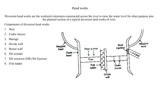
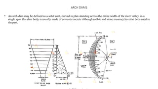
Unit 3 – Diversion and Impounding Structures
Head works –Weirs and Barrage – Types of impounding structures – Factors affecting, location of dams –Forces
on a dam – Design of Gravity dams –Earth dams, Arch dams – Spillways –Energy dissipaters.
Head works
Diversion head works are the works(or) structures constructed across the river to raise the water level for other purpose also
the planned section of a typical diversion land works of weir.
Components of diversion head works:
1. Weir
2. Under sluices
3. Barrage
4. Divide wall
5. Breast wall
6. Slit exluder
7. Slit extractor (OR) Slit Ejectors
8. Fish ladder
Cross section of weir
Causes of failure of weirs
• Uplift pressure
Remedies:
Providing sufficient thickness of impervious floor and Providing sheet piling at U/S end
level.
• Under mining or piping
Remedies:
Providing sufficient length of impervious floor to reduce percolation
Providing sheet plies as U/S and D/S ends of impervious floor to prevent under seepage of water.
• Scour on U/S and D/S of weir
Remedies:
Providing launching aprons in U/S and D/S so as to allow the stones of aprons to settle into the sour holes.
Providing sheet plies on U/S and D/S sides much below the calculated scour
• Rupture of floor dude to suction, caused by hydranic jump
Remedies :
Providing additional thickness of impervious floors.
Types of weir:
• Gravity weir
• Non – gravity weir
• Masonry weirs with vertical drops
• Rock – fill weirs with sloping aprons; and
• Concrete weirs with sloping glacis
River training works
i) Guide banks
i) The guide banks force the river into a restricted channel, and thus ensuring a smooth and an almost axial flow near
the weir site .
ii) Marginal bunds
ii) Marginal bunds are provided on the upstream side of the works in order to protect the area from submergence due
to rise in HFL caused by the afflux
iii) iii) Spurs or groynes
The canal head regulator or head sluices.
Alignment of a canal head regulator
Types of impounding structures:
1. Dam
2. Weir & barrage
3. Lake
4. Pond and any other water impounding structures
Factors affecting Dams
• Topography and geological conditions of the proposed dam site,
• Availability of suitable materials for the dam,
• The feasibility of spillway construction,
• The need to be able to cope with conditions of extreme flood or earthquake.
Location of Dams
• Catchment area.
• Foundation soil.
• Ecology.
• River cross-section at the site.
• Height of the dam.
• Storage capacity
• Costs.
• Reservoir silting.
Forces acting on a gravity Dam
• Self Weight
• Water pressure
• Uplift pressure
• Slit pressure
• Wave pressure
• Earthquake forces
• Ice pressure
• Wind pressure
• Thermal loads
Earthern dam
1. Homogeneous embankment type
2. Zoned Embankment type
3. Diaphragm type
ARCH DAMS
• An arch dam may be defined as a solid wall, curved in plan standing across the entire width of the river valley, in a
single span this dam body is usually made of cement concrete although rubble and stone masonry has also been used in
the past.
Forces Acting on Arch dams
• Self Weight
• Water pressure
• Uplift pressure
• Slit pressure
• Wave pressure
• Earthquake forces
• Ice pressure
• Wind pressure
• Thermal loads
Energy Dissipaters and Spillway Gates
• A spillways is a structure constructed at a dam site , for effectively disposing of the surplus water from upstream to
downstream.
• Just after the reservoir gets filled up, up to the normal pool level, water starts flowing over the top of the spillway crest
(which is generally kept at normal pool level) depending upon the inflow rate, water will start rising above the normal
pool level and at the same time it will be let off over the spillway.
• Straight drop spillway
• overflow spillway generally called ogee spillway .
• chute spillway often called trough spillway or open channel spillway
• side channel spillway.
• shaft spillway .
• syphon spillway
Energy Dissipaters

Unit 3 Structures for water storage and diversion

  • 1.
    Unit 3 –Diversion and Impounding Structures Head works –Weirs and Barrage – Types of impounding structures – Factors affecting, location of dams –Forces on a dam – Design of Gravity dams –Earth dams, Arch dams – Spillways –Energy dissipaters.
  • 2.
    Head works Diversion headworks are the works(or) structures constructed across the river to raise the water level for other purpose also the planned section of a typical diversion land works of weir. Components of diversion head works: 1. Weir 2. Under sluices 3. Barrage 4. Divide wall 5. Breast wall 6. Slit exluder 7. Slit extractor (OR) Slit Ejectors 8. Fish ladder
  • 3.
  • 4.
    Causes of failureof weirs • Uplift pressure Remedies: Providing sufficient thickness of impervious floor and Providing sheet piling at U/S end level. • Under mining or piping Remedies: Providing sufficient length of impervious floor to reduce percolation Providing sheet plies as U/S and D/S ends of impervious floor to prevent under seepage of water. • Scour on U/S and D/S of weir Remedies: Providing launching aprons in U/S and D/S so as to allow the stones of aprons to settle into the sour holes. Providing sheet plies on U/S and D/S sides much below the calculated scour • Rupture of floor dude to suction, caused by hydranic jump Remedies : Providing additional thickness of impervious floors.
  • 5.
    Types of weir: •Gravity weir • Non – gravity weir • Masonry weirs with vertical drops • Rock – fill weirs with sloping aprons; and • Concrete weirs with sloping glacis
  • 6.
    River training works i)Guide banks i) The guide banks force the river into a restricted channel, and thus ensuring a smooth and an almost axial flow near the weir site . ii) Marginal bunds ii) Marginal bunds are provided on the upstream side of the works in order to protect the area from submergence due to rise in HFL caused by the afflux iii) iii) Spurs or groynes
  • 7.
    The canal headregulator or head sluices.
  • 8.
    Alignment of acanal head regulator
  • 9.
    Types of impoundingstructures: 1. Dam 2. Weir & barrage 3. Lake 4. Pond and any other water impounding structures
  • 10.
    Factors affecting Dams •Topography and geological conditions of the proposed dam site, • Availability of suitable materials for the dam, • The feasibility of spillway construction, • The need to be able to cope with conditions of extreme flood or earthquake.
  • 11.
    Location of Dams •Catchment area. • Foundation soil. • Ecology. • River cross-section at the site. • Height of the dam. • Storage capacity • Costs. • Reservoir silting.
  • 12.
    Forces acting ona gravity Dam • Self Weight • Water pressure • Uplift pressure • Slit pressure • Wave pressure • Earthquake forces • Ice pressure • Wind pressure • Thermal loads
  • 13.
    Earthern dam 1. Homogeneousembankment type 2. Zoned Embankment type 3. Diaphragm type
  • 14.
    ARCH DAMS • Anarch dam may be defined as a solid wall, curved in plan standing across the entire width of the river valley, in a single span this dam body is usually made of cement concrete although rubble and stone masonry has also been used in the past.
  • 15.
    Forces Acting onArch dams • Self Weight • Water pressure • Uplift pressure • Slit pressure • Wave pressure • Earthquake forces • Ice pressure • Wind pressure • Thermal loads
  • 16.
    Energy Dissipaters andSpillway Gates • A spillways is a structure constructed at a dam site , for effectively disposing of the surplus water from upstream to downstream. • Just after the reservoir gets filled up, up to the normal pool level, water starts flowing over the top of the spillway crest (which is generally kept at normal pool level) depending upon the inflow rate, water will start rising above the normal pool level and at the same time it will be let off over the spillway.
  • 17.
    • Straight dropspillway • overflow spillway generally called ogee spillway . • chute spillway often called trough spillway or open channel spillway • side channel spillway. • shaft spillway . • syphon spillway
  • 22.