1. Open the network topology and identify the components such as servers, routers, and end devices.
2. Connect all cables between network devices as specified in the connections table to ensure connectivity.
3. Configure the IP addresses on end devices using the address table by accessing each device's desktop interface.
Step by Step guide to set up a simple network in Packet TracerSorath Asnani
This document shows the detailed Steps to set up a simple network inside Packet Tracer. You will get familiarity with the software after following the Steps.
Step by Step guide to set up a simple network in Packet TracerSorath Asnani
This document shows the detailed Steps to set up a simple network inside Packet Tracer. You will get familiarity with the software after following the Steps.
LAN Design Project Packet Tracer CSCI 356 - 50 poi.docxsmile790243
LAN Design Project
Packet Tracer
CSCI 356 - 50 points
Scenario:
You have been tasked with designing your new corporate network since they found out you
have studied IP addressing, Cisco networking, and routing. Below is a screen shot of the
topology for your network:
You are responsible for the following tasks:
Design and Implement IPv4 addressing plan
Includes putting addresses on all PCs, switches, and routers
Design and Implement basic configurations for Switch 1 and Switch 2
Hostnames, Management IP address for VLAN 1, enable secret password, line console
password and Message of the Day Warning banner. Put proper default gateway address
on Switch 1 and Switch 2.
Design and Implement basic configurations on all 3 routers:
Hostnames, IP addresses on proper interfaces, enable secret password, line console
password and Message of the Day Warning banner.
Design and Implement SSH on switches
Create proper addressing on VLAN 1, usernames & passwords on Switch 1 and Switch 2
Design and Implement SSH on all 3 routers.
Create usernames & passwords on Corporate Router, ISP router and Branch office
router
Design and Implement static routing on all 3 routers so that all networks are reachable.
Create proper static routes on routers to reach all other networks.
Details on Addressing:
You have been given the following major IP address: _________________________________
NOTE: You will each have your own different major IP address that you need to subnet. In
other words, everyone will have a slightly different problem!
You need to subnet that into 4 separate networks.
Network 1 subnet - Corporate LAN
Network 2 subnet - Connection between Corp Router G0/0 to ISP G0/0
Network 3 subnet - Connection between ISP Router G0/1 to Branch office Router G0/1
Network 4 subnet - Branch Office LAN
Put proper addressing on Corporate Router interfaces G0/0 and G0/1
Put proper addressing on ISP router G0/0 and G0/1
Put proper addressing on Branch Office Router G0/0 and G0/1
Turn on all interfaces on all 3 routers by issuing the no shutdown command for each interface
Put VLAN 1 ip address on Switch 1 - Should be address in Network 1 Corporate LAN subnet
Put VLAN 1 ip address on Switch 2 - should be address in Network 4 Branch office LAN
subnet.
Put proper addressing, subnet mask and default gateway on PCs and Server in Corporate LAN.
They should use addresses in Network 1 subnet.
Put proper addressing, subnet mask and default gateway on PCs in Branch Office LAN. They
should use addresses from Network 4 subnet.
Configure static routing on all 3 routers.
Corporate router will need a route to Branch office LAN and connection between ISP and
Branch router.
ISP router will need a route to Corporate LAN and Branch office LAN
Branch router will need a route to Corporate LAN and connection between ISP and Corp router.
TESTING & VALIDATI ...
Labs cisco ccna icnd1 proposé par firebrandtraining pour appliqué les connaissances apporté.
les bonnes pratiques dans le domaine reseau informatique vous obliger de faire des labs après la fin de chaque chapitre abordé dans les classes cisco.
tep 2 Display the switch MAC address .pdffurqanfazl2
tep 2: Display the switch MAC address table. Console into your switch and view the MAC
address table before and after running network communication lests with ping. a) Establish a
console connection to your switch and enter privileged EXEC mode. b) In privileged EXEC
mode, type the show mac address-table command and press Enter. Switch-?\# show mac
address-table Even though no network communication has been initialed across the network (i.e.,
no use of ping), the switch may have learned MAC addresses from its connection to the PC and
the other switch. Are there any MAC addresses recorded in the MAC address table? What MAC
addresses are recorded in the table? To which switch ports are they mapped, and to which
devices do they belong? Ignore MAC addresses that are mapped to the CPU. If you had yet to
previously record the MAC addresses of network devices in Step 1, how could you tell which
devices the MAC addresses belong to, using only the output from the show mac address-table
command? Does it work in all scenarios? Step 3: Clear your Switch MAC address table and
display the MAC address table again. a. In privileged EXEC mode, type the clear mac address-
table dynamic command and press Enter.
Addressing Table Objectives Part 1: Build and Configure the Network Part 2: Examine the
Switch MAC Address Table Background / Scenario The purpose of a Layer 2 LAN switch is to
deliver Ethernet frames to host devices on the local network. The switch records host MAC
addresses that are visible on the network and maps those MAC addresses to its own Ethernet
switch ports. This process is called building the MAC address table. When a switch receives a
frame from a PC, it examines its source and destination MAC addresses. The source MAC
address is recorded and mapped to the switch port from which it arrived. Then, the destination
MAC address is looked up in the MAC address table. If the destination MAC address is a known
address, the frame is forwarded out of the corresponding switch port associated with that MAC
address. If the MAC address is unknown, the
c. From a console connection to your switch, enter the show mac address-table command. Has
the switch added additional MAC addresses to the MAC address table? If so, which addresses
and devices? d. From your PC, open a command prompt and retype arp - a. Does the ARP cache
have additional entries for all network devices that received pings? Reflection Question On
Ethernet networks, data is delivered to devices by their MAC addresses. For this to happen,
switches and PCs dynamically build ARP caches and MAC address tables. This process seems
easy with only a few computers on the network. What might be some of the challenges on more
extensive networks? Running-Config Output In privileged EXEC mode, type the show running-
configuration command and press Enter. Press the Space Bar until you get to the bottom of the
output. Copy all the configuration and paste it below.
Switch-?\# clear mac address-table dynamic .
CCNA Voice Primer MaterialsCCNA Voice Primer MaterialsVo.docxtidwellveronique
CCNA Voice Primer Materials
Voice Primer Packet Tracer Lab
Topology
Fa0/1
Fa0/1
Fa0/4
Fa0/1
Fa0/3
Fa0/2
Fa0/3
Fa0/2
Fa0/1
Fa0/0
Fa0/0
Objective
Use Packet Tracer to configure Cisco Unified Communications Manager Express (CUCME) in a basic two site topology.
Background
Cisco Unified Communications Manager Express (CUCME) is VoIP call management software which runs within the router IOS. In this lab you will practice some of the basic CUCME and voice related configuration commands which would enable IP and analog phones at two locations to communicate. You will also apply many of the configuration skills learned in your CCNA curriculum.
Note: Packet Tracer (PT) is a simulation tool not an emulation tool. It is somewhat limited in its capabilities, especially in the VoIP area. Many commands, especially show and debug commands, which could be utilized to troubleshoot this lab are not supported in the PT environment. You may optionally use physical hardware for a richer experience with this lab if you have access to the appropriate hardware and software.
Note: This lab is introducing concepts which are probably not familiar to you. Be sure to read and follow all of the directions carefully or things will probably not work as you expect.
Required Resources
You will need the following tools to complete this lab:
· Packet Tracer software version 5.3.3 or later
IP Addressing Table
Device
Interface
Address
RouterA-1
FastEthernet0/0
n/a
FastEthernet0/0.10
172.16.10.1 /24
FastEthernet0/0.20
172.16.20.1 /24
FastEthernet0/0.99
172.16.99.1 /24
FastEthernet0/1
10.0.0.1/24
RouterB-1
FastEthernet0/0
n/a
FastEthernet0/0.10
172.17.10.1 /24
FastEthernet0/0.20
172.17.20.1 /24
FastEthernet0/0.99
172.17.99.1 /24
FastEthernet0/1
10.0.0.2/24
SwitchA-1
Vlan99
172.16.99.2
SwitchB-1
Vlan99
172.17.99.2
Step 1: Build the Packet Tracer Topology.
Open a new PT file and use the device and connections tools in PT to build the topology shown on the first page of this lab. The IP phones at site A will be receiving Power over Ethernet (PoE) from the switch but the IP phones at site B should be configured with power supplies.
Step 2: Perform basic device configuration.
On each router and switch:
· Set the hostname as indicated on the topology diagram
· Set the enable secret to class
· Disable DNS lookups
· Set a Telnet and Console password of cisco
· Set IP addresses as indicated on the above chart
On each switch:
· Create VLAN 10 with the name VOICE
· Create VLAN 20 with the name DATA
· Create VLAN 99 with the name MANAGEMENT
On each PC:
· Configure to receive IP address via DHCP
Step 3: Configure DHCP service on the routers.
The VoIP devices and PCs in PT need to receive IP addressing information by DHCP. Each router will need to act as the DHCP server for its location. We will be separating the voice and data networks at each location so we will need two DHCP pools. The special DHCP option 150 is used to send the CUCME address to the V ...
Supportive Security Policies in SOHOTopic SUPPORTIVE SECURI.docxpicklesvalery
Supportive Security Policies in SOHO
Topic: SUPPORTIVE SECURITY POLICIES IN SOHO
NETWORKING
It is a supportive system of sharing information and services among individuals and groups having a common interest.
A local-area network (LAN) is basically defined as two or more computers connected by a structured wire system for the purpose of sharing resources and files. In this chapter we will explain the various ‘structured wire systems’ that the Network Engineer will deal with during the course of their job. Wireless LANs are becoming more and more popular, but even these devices rely on some amount of physical wires in most cases.
REQUIREMENTS
Network Adapter
A computer needs a network adapter to connect to a network. It converts computer data into electronic signals. It listens for silence on the network cable and applies the data to it when it has an opportunity. The network access element of its job is called Media Access Control, or MAC. The physical address of every computer on a network is called its MAC address. The MAC address is the network adapter's serial number. Most computers are shipped with the network adapter integrated into the motherboard. However, early PCs didn't include this function and computer owners had to buy it separately and fit it into an expansion slot on the motherboard. These were called "network cards" because they were sold on a separate card. Although network adapters are now integrated, the name network card is still used. The wireless equivalent is called a Wireless Network Interface Controller.
Network Medium
Wired networks need cable. The most common form of cable used in networks is called the "Unshielded Twisted Pair." In PC shops, it is generally just referred to as "network cable" or "Ethernet cable." Ethernet is the most widely implemented set of standards for the physical properties of networks. UTP is so closely identified with Ethernet that it is often given that name. Other cable types used for networks are twin-axial, Shielded Twisted Pair and single-mode and multi-mode fiber optic cable. Wireless networks don't need cable; they send data on radio waves generated by the WNIC.
Cable Connectors
In wired networks, the most common form of connector is the RJ45. Every computer with networking capabilities has an RJ45 port. This is sometimes called a "network port" or an "Ethernet port." The RJ45 plug looks like a slightly larger telephone plug and connects the Unshielded Twisted Pair or the Shielded Twisted Pair cable.
Power Supply
Both wired and wireless networks need a power supply. A wireless network uses the current to generate radio waves. A cabled network sends data interpreted as an electronic pulse.
Hub/Switch/Router
In wired networks, one computer cannot connect to many others without some form of splitter. A hub is little more than a splitter. It repeats any signals coming into one of its ports out onto all its other ports. A cable leads from each port to one computer. A switch ...
VLAN, Trunk and 802.1q Router Configuration Objectiv.docxdickonsondorris
VLAN, Trunk and 802.1q Router Configuration
Objectives
Initial Configuration
VLAN Trunking Configuration
802.1q Router/Switch trunking
Topology
You can click the Show Lab Content button to download the lab or you can download the l ab from
[email protected] in Content.
VLAN, Trunk and 802.1q Router Configuration
Step 1: Initial Switch Configuration
Configure hostnames on the switches
Configure enable secret, console and vty (Telnet) passwords as uwstout
Configure VLANs 10, 20 and 30 on StoutSW1 and StoutSW2
Configure the ports the PCs are connected to in the proper vlans
Shutdown the fa0/4 interfaces on each switch
Configure an IEEE 802.1Q trunk between StoutSW1 and StoutSW2 using the fa0/1 interfaces
Configure the IP addresses and subnet masks on PC1a, PC1b and PC2 according to the topology
diagram
Verify your configuration before moving on to Step 2
If you need help remembering the commands for the initial configuration steps, try using ? or refer to the
previous labs.
Before moving to Step 2 verify your trunk and VLAN configuration, PC IP addresses and that the switchports
for the PCs are in the correct vlans. Use “show” commands and ipconfig to verify the initial configuration.
VLAN, Trunk and 802.1q Router Configuration
Step 2: Configure 802.1 trunk between Menomonie and StoutSW1
Data from one vlan cannot cross into another vlan without the help of a router to route the data. Currently
the PCs cannot successfully send to each other because they are on different VLANs. In this step you will
configure a trunk between the Menomonie router and the StoutSW1 switch. (This type of configuration is
referred to as “Router-on-a-Stick”) so the router can be used to route traffic between the VLANs. The
physical interface on the router that is connected to StoutSW1 is fastethernet0/1 so you will configure the
trunked sub-interfaces on the fastethernet0/1 interface. Then configure fastethernet0/8 on StoutSW1 to trunk.
Configure the Router:
Configure the hostname on the router to Menomonie:
In global configuration mode type, hostname Menomonie
Configure the first sub-interface on Menomonie to route vlan 10
In global configuration mode type, interface fastethernet0/1.10
In interface configuration mode for fa0/1.10 type, encapsulation dot1q 10
Configure the second sub-interface on Menomonie to route vlan 20
In global configuration mode type, interface fastethernet0/1.20
In interface configuration mode for fa0/1.20 type, encapsulation dot1q 20
Configure the third sub-interface on Menomonie to route vlan 30
In global configuration mode type, interface fastethernet0/1.30
In interface configuration mode for fa0/1.30 type, encapsulation dot1q 30
Now that the virtual trunked interfaces have been configured you can assign an IP address to the
interfaces. The addresses for each inter ...
The French Revolution, which began in 1789, was a period of radical social and political upheaval in France. It marked the decline of absolute monarchies, the rise of secular and democratic republics, and the eventual rise of Napoleon Bonaparte. This revolutionary period is crucial in understanding the transition from feudalism to modernity in Europe.
For more information, visit-www.vavaclasses.com
Model Attribute Check Company Auto PropertyCeline George
In Odoo, the multi-company feature allows you to manage multiple companies within a single Odoo database instance. Each company can have its own configurations while still sharing common resources such as products, customers, and suppliers.
A Strategic Approach: GenAI in EducationPeter Windle
Artificial Intelligence (AI) technologies such as Generative AI, Image Generators and Large Language Models have had a dramatic impact on teaching, learning and assessment over the past 18 months. The most immediate threat AI posed was to Academic Integrity with Higher Education Institutes (HEIs) focusing their efforts on combating the use of GenAI in assessment. Guidelines were developed for staff and students, policies put in place too. Innovative educators have forged paths in the use of Generative AI for teaching, learning and assessments leading to pockets of transformation springing up across HEIs, often with little or no top-down guidance, support or direction.
This Gasta posits a strategic approach to integrating AI into HEIs to prepare staff, students and the curriculum for an evolving world and workplace. We will highlight the advantages of working with these technologies beyond the realm of teaching, learning and assessment by considering prompt engineering skills, industry impact, curriculum changes, and the need for staff upskilling. In contrast, not engaging strategically with Generative AI poses risks, including falling behind peers, missed opportunities and failing to ensure our graduates remain employable. The rapid evolution of AI technologies necessitates a proactive and strategic approach if we are to remain relevant.
2024.06.01 Introducing a competency framework for languag learning materials ...Sandy Millin
http://sandymillin.wordpress.com/iateflwebinar2024
Published classroom materials form the basis of syllabuses, drive teacher professional development, and have a potentially huge influence on learners, teachers and education systems. All teachers also create their own materials, whether a few sentences on a blackboard, a highly-structured fully-realised online course, or anything in between. Despite this, the knowledge and skills needed to create effective language learning materials are rarely part of teacher training, and are mostly learnt by trial and error.
Knowledge and skills frameworks, generally called competency frameworks, for ELT teachers, trainers and managers have existed for a few years now. However, until I created one for my MA dissertation, there wasn’t one drawing together what we need to know and do to be able to effectively produce language learning materials.
This webinar will introduce you to my framework, highlighting the key competencies I identified from my research. It will also show how anybody involved in language teaching (any language, not just English!), teacher training, managing schools or developing language learning materials can benefit from using the framework.
June 3, 2024 Anti-Semitism Letter Sent to MIT President Kornbluth and MIT Cor...Levi Shapiro
Letter from the Congress of the United States regarding Anti-Semitism sent June 3rd to MIT President Sally Kornbluth, MIT Corp Chair, Mark Gorenberg
Dear Dr. Kornbluth and Mr. Gorenberg,
The US House of Representatives is deeply concerned by ongoing and pervasive acts of antisemitic
harassment and intimidation at the Massachusetts Institute of Technology (MIT). Failing to act decisively to ensure a safe learning environment for all students would be a grave dereliction of your responsibilities as President of MIT and Chair of the MIT Corporation.
This Congress will not stand idly by and allow an environment hostile to Jewish students to persist. The House believes that your institution is in violation of Title VI of the Civil Rights Act, and the inability or
unwillingness to rectify this violation through action requires accountability.
Postsecondary education is a unique opportunity for students to learn and have their ideas and beliefs challenged. However, universities receiving hundreds of millions of federal funds annually have denied
students that opportunity and have been hijacked to become venues for the promotion of terrorism, antisemitic harassment and intimidation, unlawful encampments, and in some cases, assaults and riots.
The House of Representatives will not countenance the use of federal funds to indoctrinate students into hateful, antisemitic, anti-American supporters of terrorism. Investigations into campus antisemitism by the Committee on Education and the Workforce and the Committee on Ways and Means have been expanded into a Congress-wide probe across all relevant jurisdictions to address this national crisis. The undersigned Committees will conduct oversight into the use of federal funds at MIT and its learning environment under authorities granted to each Committee.
• The Committee on Education and the Workforce has been investigating your institution since December 7, 2023. The Committee has broad jurisdiction over postsecondary education, including its compliance with Title VI of the Civil Rights Act, campus safety concerns over disruptions to the learning environment, and the awarding of federal student aid under the Higher Education Act.
• The Committee on Oversight and Accountability is investigating the sources of funding and other support flowing to groups espousing pro-Hamas propaganda and engaged in antisemitic harassment and intimidation of students. The Committee on Oversight and Accountability is the principal oversight committee of the US House of Representatives and has broad authority to investigate “any matter” at “any time” under House Rule X.
• The Committee on Ways and Means has been investigating several universities since November 15, 2023, when the Committee held a hearing entitled From Ivory Towers to Dark Corners: Investigating the Nexus Between Antisemitism, Tax-Exempt Universities, and Terror Financing. The Committee followed the hearing with letters to those institutions on January 10, 202
Francesca Gottschalk - How can education support child empowerment.pptxEduSkills OECD
Francesca Gottschalk from the OECD’s Centre for Educational Research and Innovation presents at the Ask an Expert Webinar: How can education support child empowerment?
Synthetic Fiber Construction in lab .pptxPavel ( NSTU)
Synthetic fiber production is a fascinating and complex field that blends chemistry, engineering, and environmental science. By understanding these aspects, students can gain a comprehensive view of synthetic fiber production, its impact on society and the environment, and the potential for future innovations. Synthetic fibers play a crucial role in modern society, impacting various aspects of daily life, industry, and the environment. ynthetic fibers are integral to modern life, offering a range of benefits from cost-effectiveness and versatility to innovative applications and performance characteristics. While they pose environmental challenges, ongoing research and development aim to create more sustainable and eco-friendly alternatives. Understanding the importance of synthetic fibers helps in appreciating their role in the economy, industry, and daily life, while also emphasizing the need for sustainable practices and innovation.
Honest Reviews of Tim Han LMA Course Program.pptxtimhan337
Personal development courses are widely available today, with each one promising life-changing outcomes. Tim Han’s Life Mastery Achievers (LMA) Course has drawn a lot of interest. In addition to offering my frank assessment of Success Insider’s LMA Course, this piece examines the course’s effects via a variety of Tim Han LMA course reviews and Success Insider comments.
How to Make a Field invisible in Odoo 17Celine George
It is possible to hide or invisible some fields in odoo. Commonly using “invisible” attribute in the field definition to invisible the fields. This slide will show how to make a field invisible in odoo 17.
Embracing GenAI - A Strategic ImperativePeter Windle
Artificial Intelligence (AI) technologies such as Generative AI, Image Generators and Large Language Models have had a dramatic impact on teaching, learning and assessment over the past 18 months. The most immediate threat AI posed was to Academic Integrity with Higher Education Institutes (HEIs) focusing their efforts on combating the use of GenAI in assessment. Guidelines were developed for staff and students, policies put in place too. Innovative educators have forged paths in the use of Generative AI for teaching, learning and assessments leading to pockets of transformation springing up across HEIs, often with little or no top-down guidance, support or direction.
This Gasta posits a strategic approach to integrating AI into HEIs to prepare staff, students and the curriculum for an evolving world and workplace. We will highlight the advantages of working with these technologies beyond the realm of teaching, learning and assessment by considering prompt engineering skills, industry impact, curriculum changes, and the need for staff upskilling. In contrast, not engaging strategically with Generative AI poses risks, including falling behind peers, missed opportunities and failing to ensure our graduates remain employable. The rapid evolution of AI technologies necessitates a proactive and strategic approach if we are to remain relevant.
Digital Tools and AI for Teaching Learning and Research
Steps
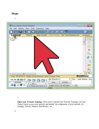
1. Steps
1.
1
Open your Network Topology. Once you've opened your Network Topology on Cisco
Packet Tracer, access your network and identify the components of your network, for
example; Servers, Routers, End Devices, etc.
2.
2. 2
Complete the cabling. Access the cables section and connect completely and correctly
the cables between the network in order to ensure connectivity between the devices in the
network using the connections table given.
3.
3. 3
Configure the IP addresses on the end devices. Using the address table still, correctly
and completely configure the IP addresses on all end devices. This can be done by
accessing the desktop platform on each device and locating the IP configuration section.
The reason for doing this is to enable the devices be on the right network.
4.
4. 4
Configure the IP addresses on your routers and switches. After configuring the right
IP addresses on the end devices, you will have to do the same on the routers and switches
also, using the address table. But this time in a different way because there's no desktop
platform on the routers and switches. You will have to access the configuration panel on
both devices and this can be done in two ways:
o Click on the device and open the Command Line Interface (CLI) and then type in
the right commands to configure the right addresses for the router using the
addressing table.
o Use a console cable from an end device and connect it to the device you wish to
configure and access the terminal platform on the end device and it will take you
5. to the device's Command Line Interface and then you type in the commands in
other to configure the right addresses.
5.
5
Configure your default gateway. After configuring the IP addresses, you will need to
configure the default gateway also. The reason for this is so the end devices would know
what network they are operating on. You can find the default gateway either in the
addressing table (if given) or in the network topology.
6.
6. 6
Test connectivity. After configuring the addresses, you will have to test connectivity by
opening a command prompt window on the end devices and try pinging the address
which the network operates on. If it gives you a reply, it means your network was
configured correctly.