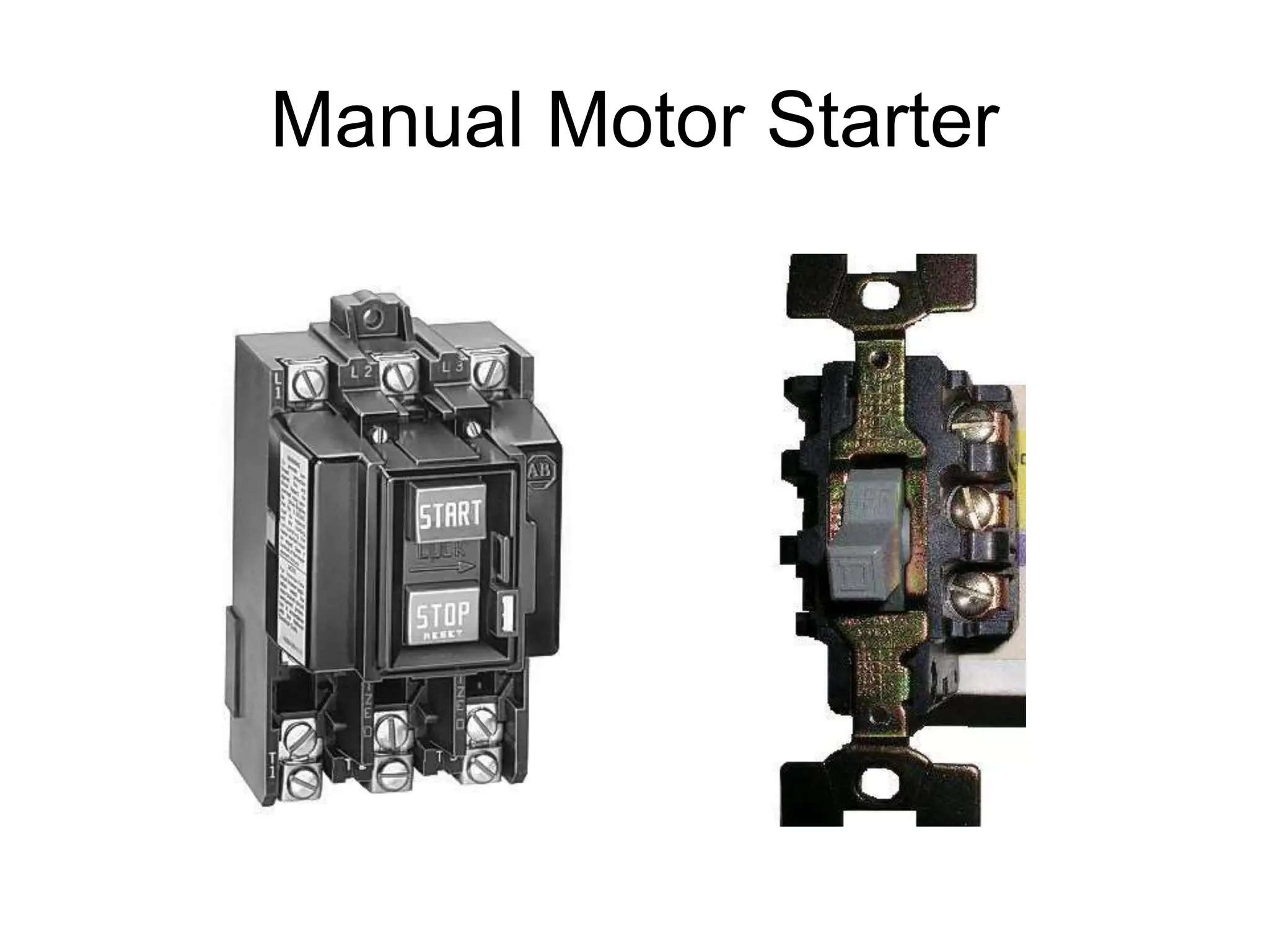
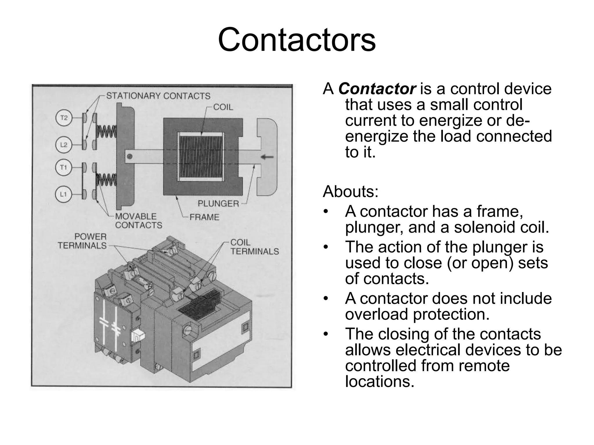
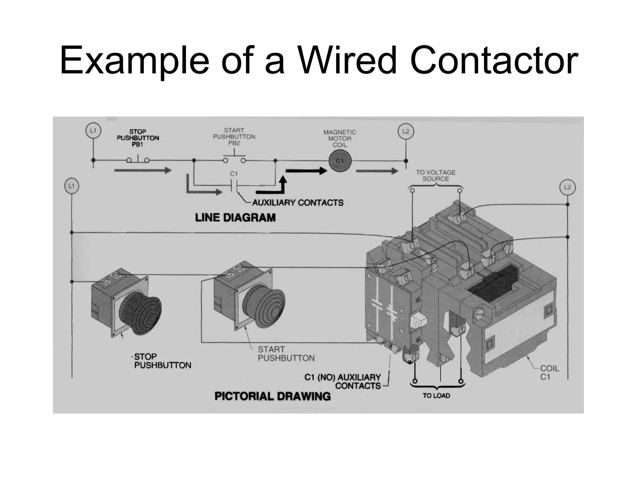
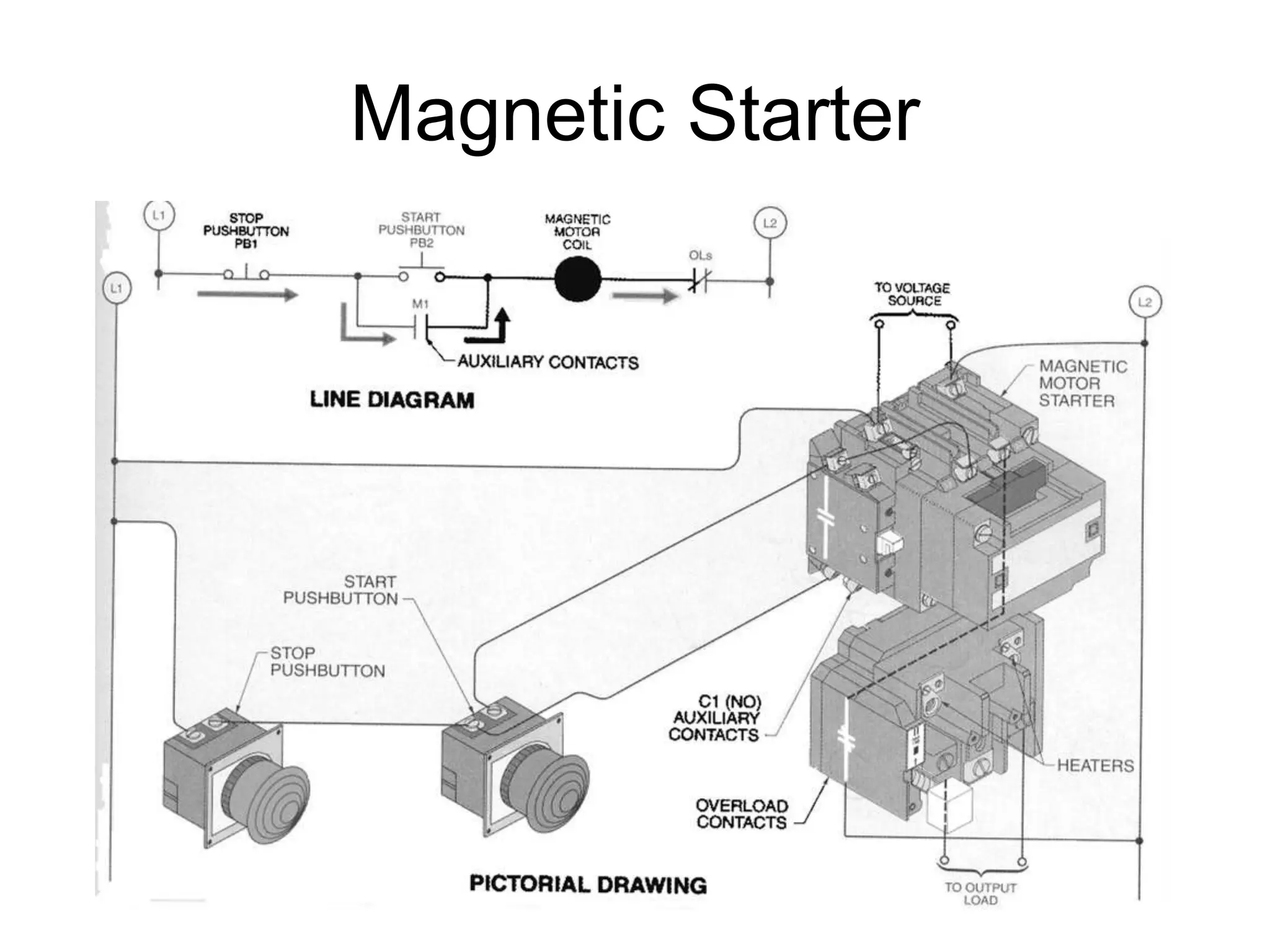
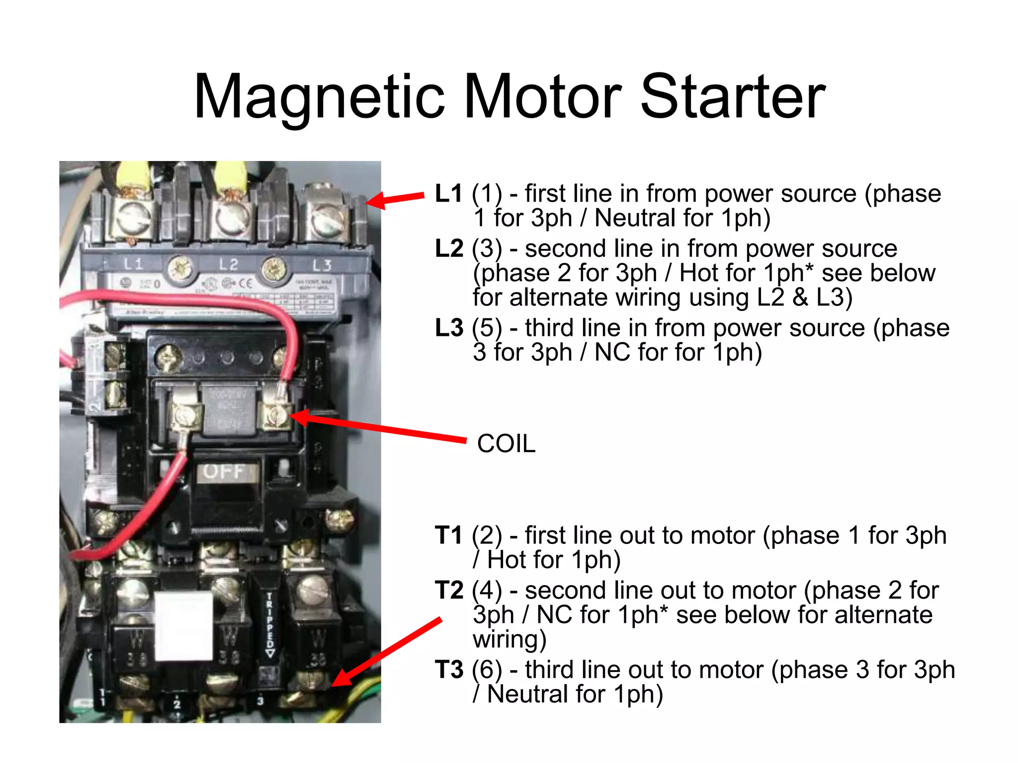
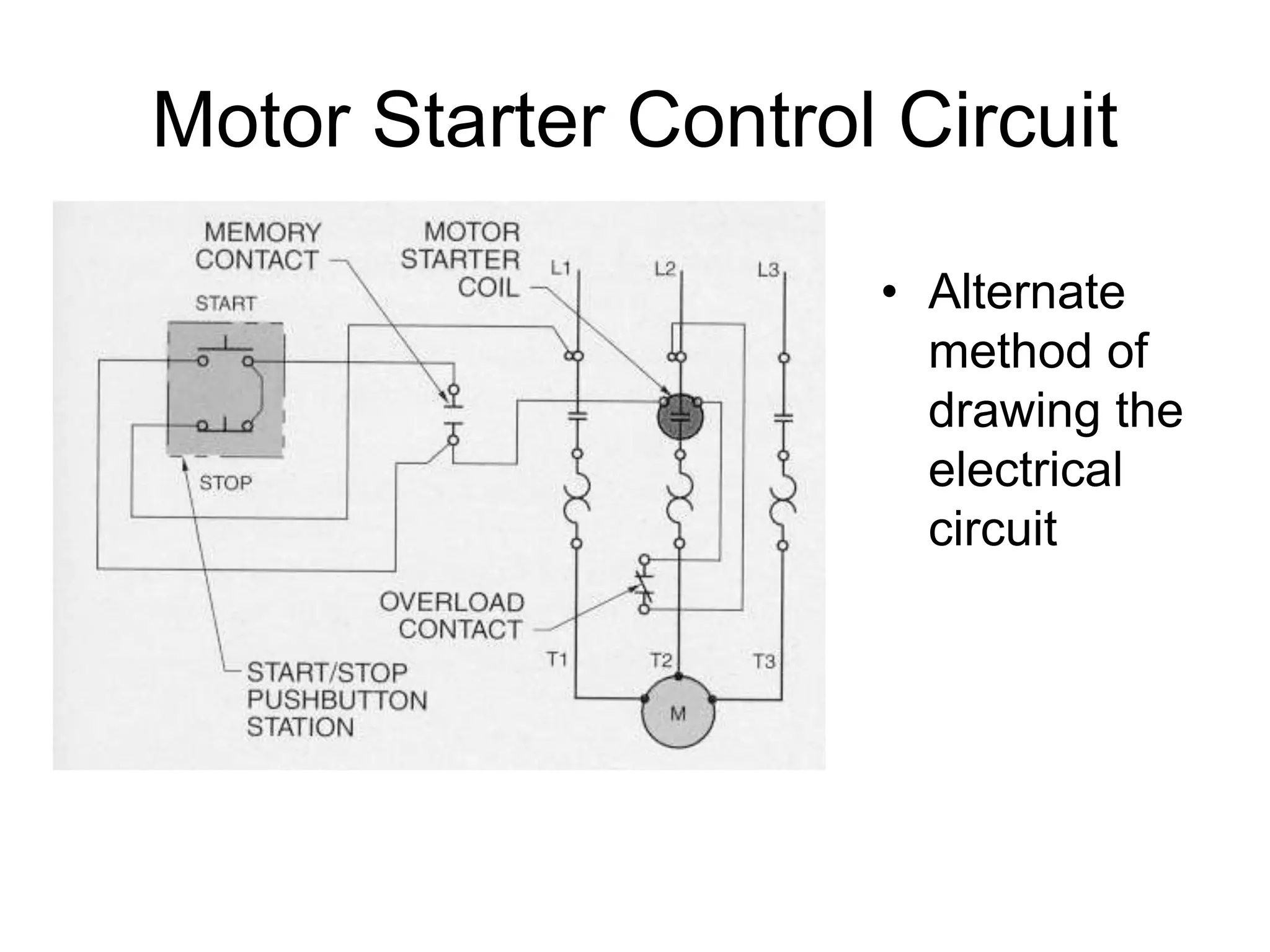
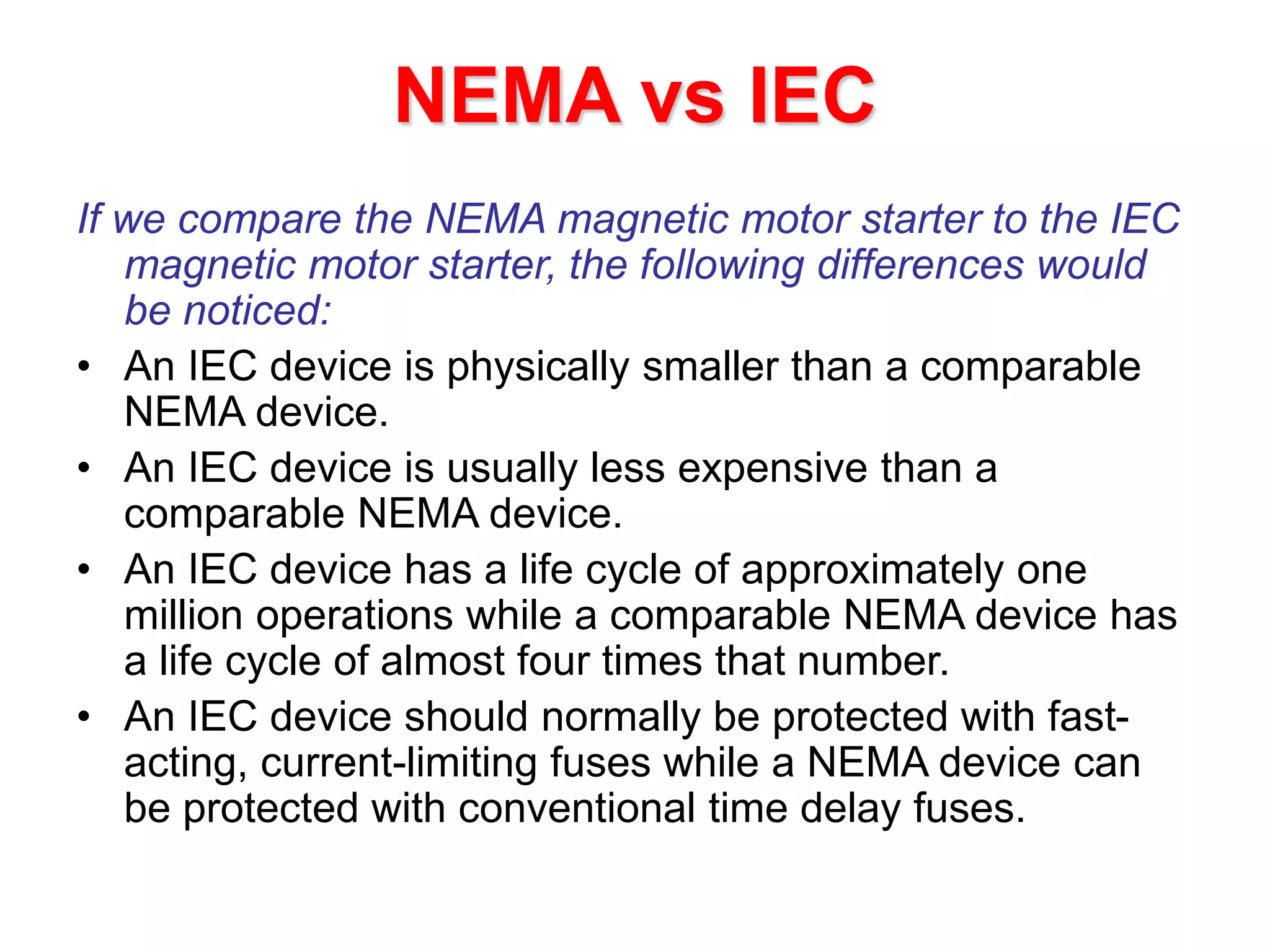
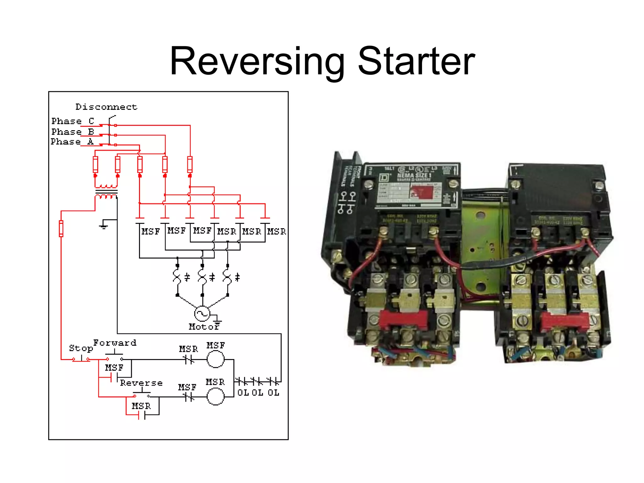
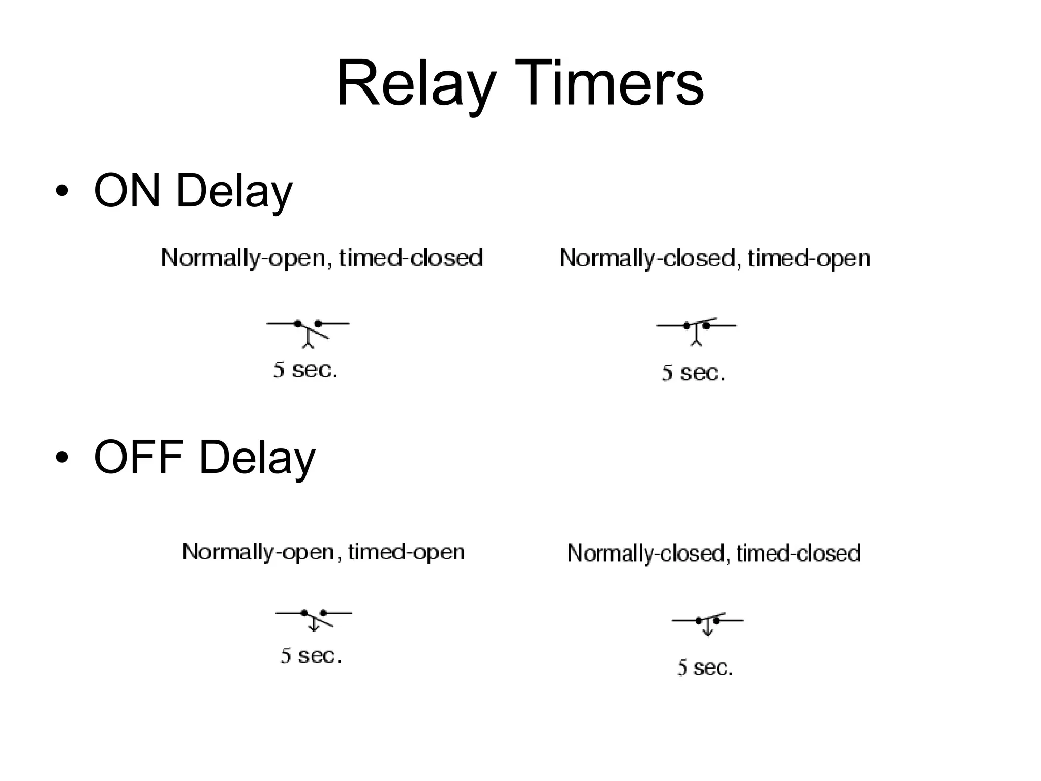
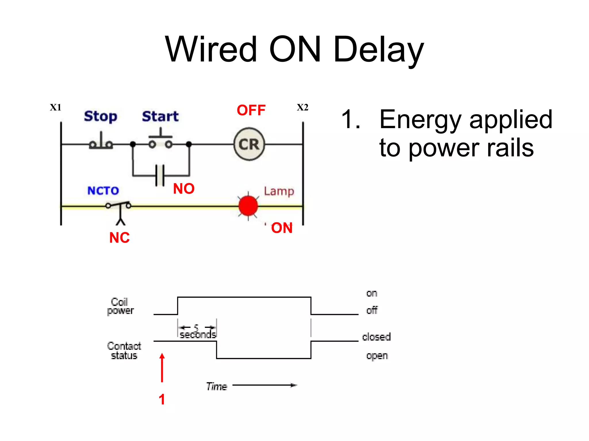
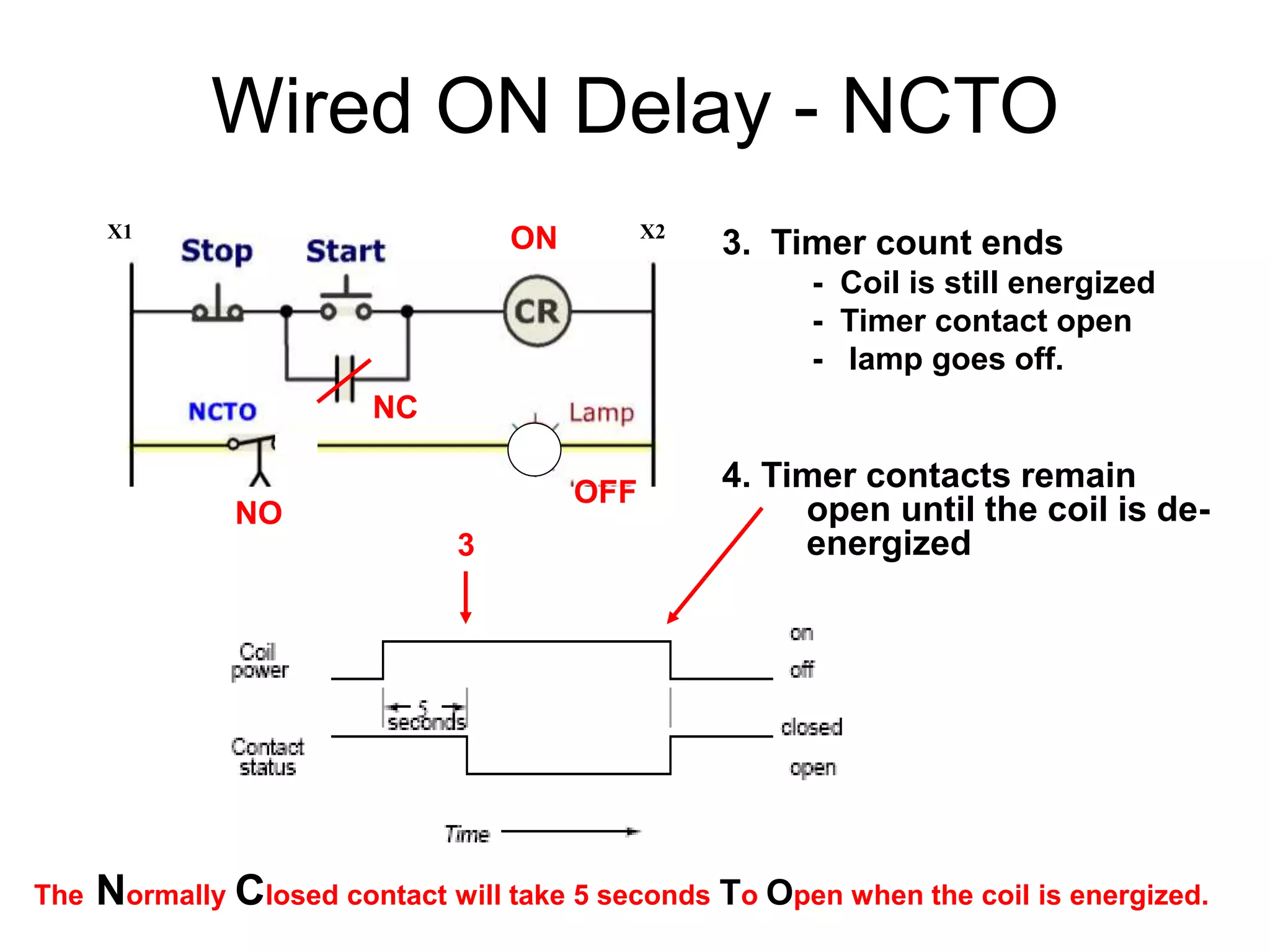
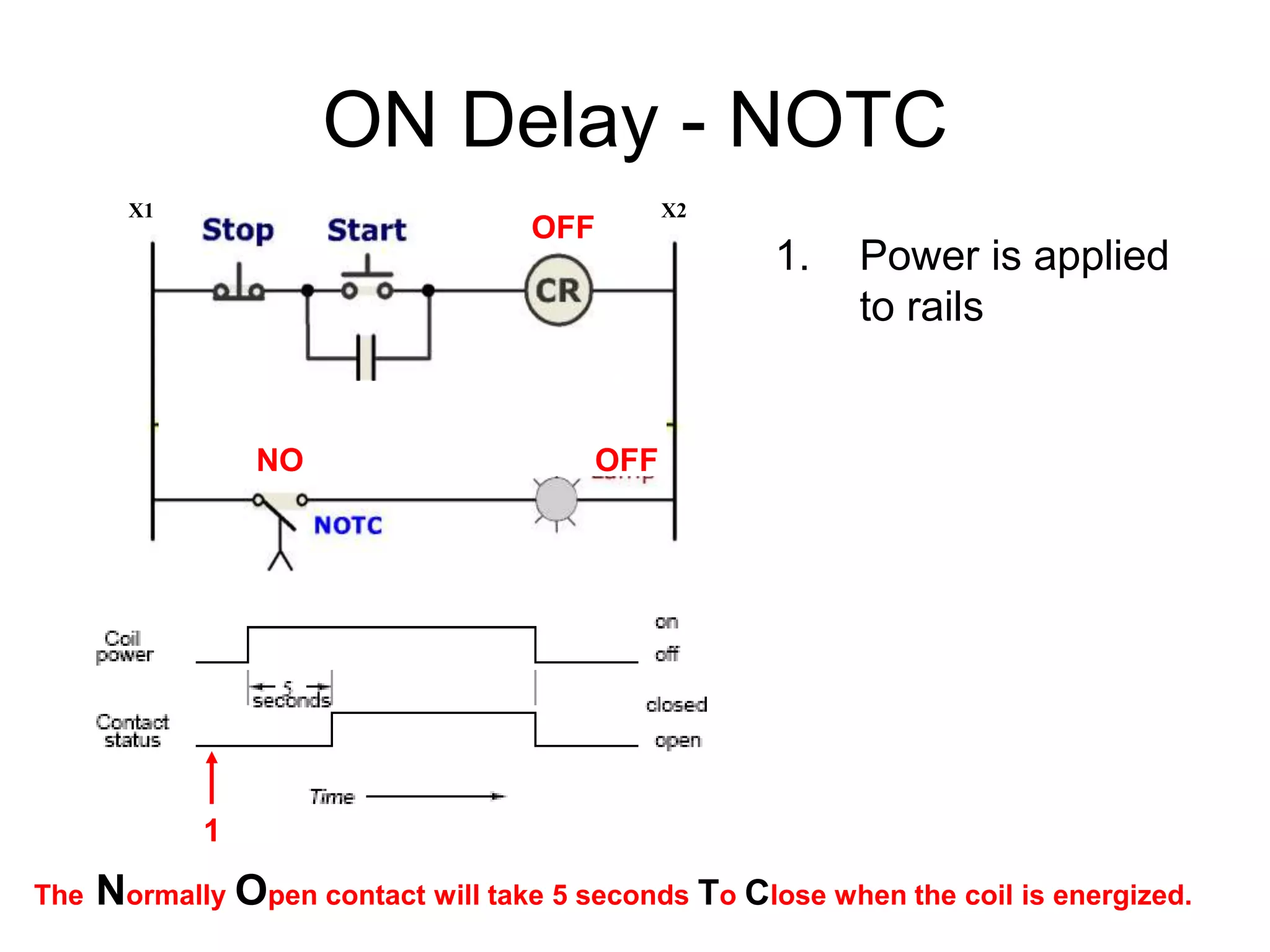
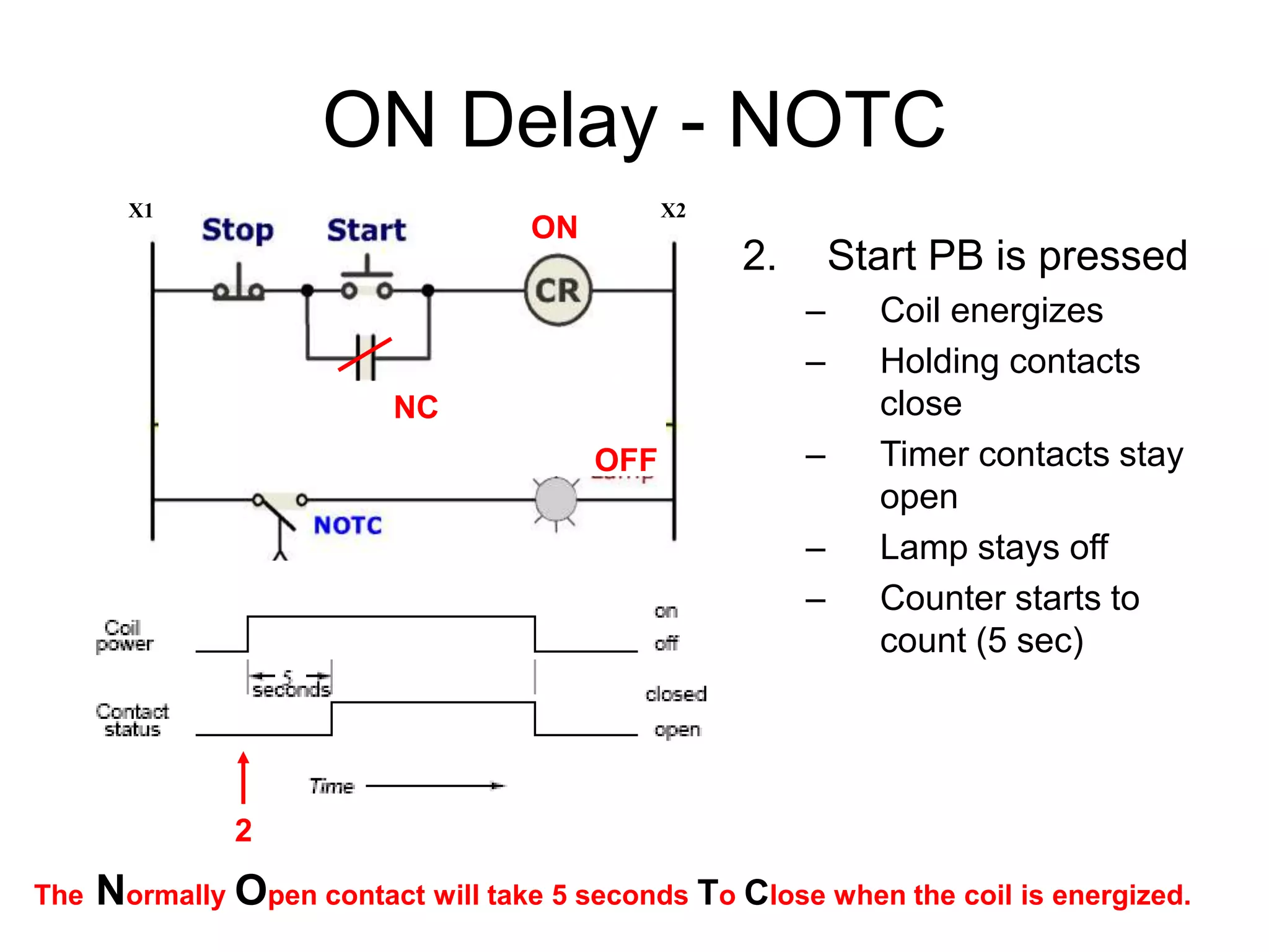
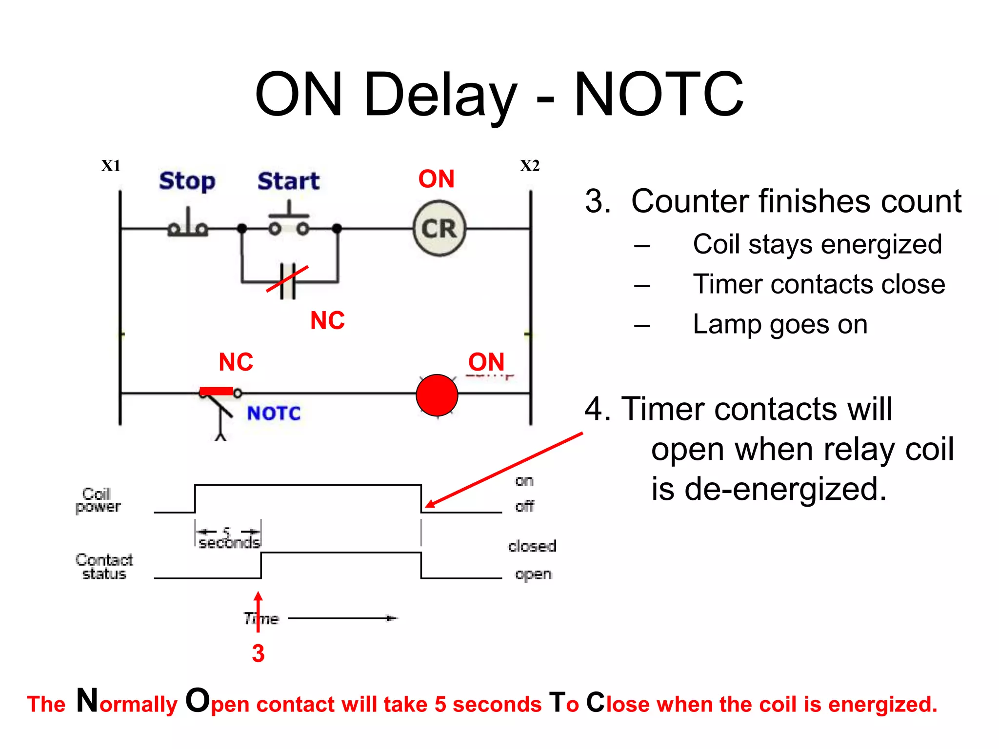
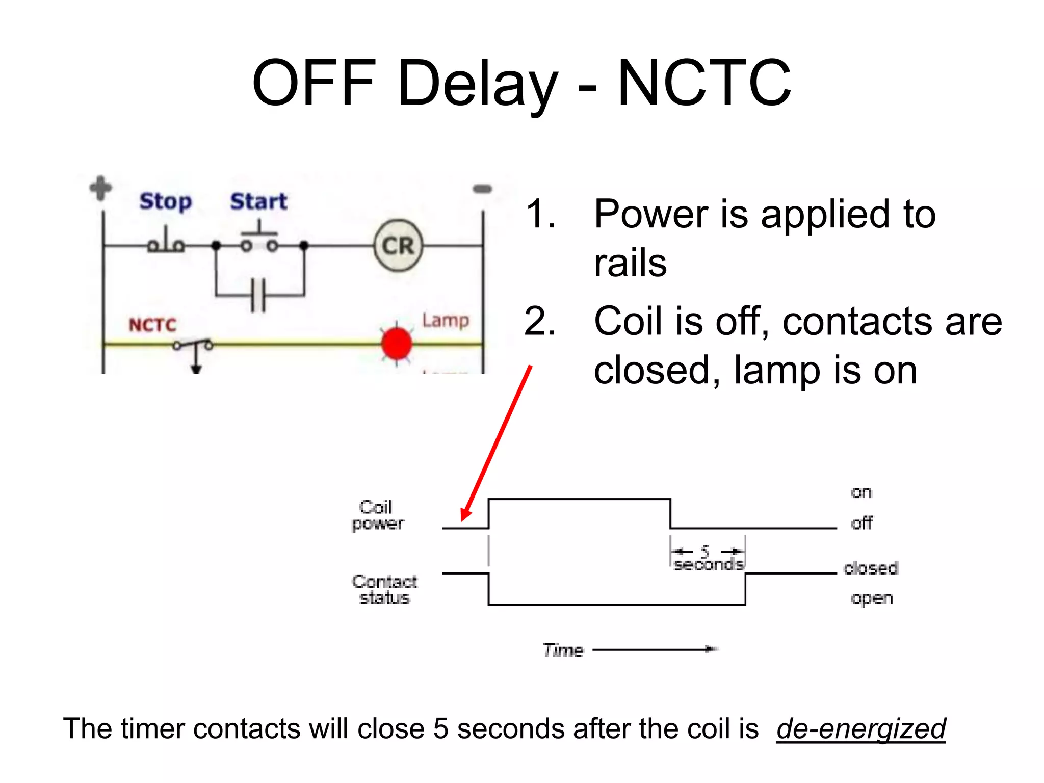
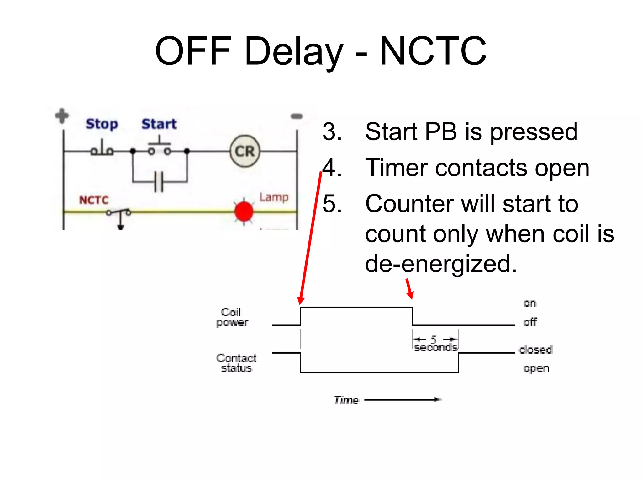
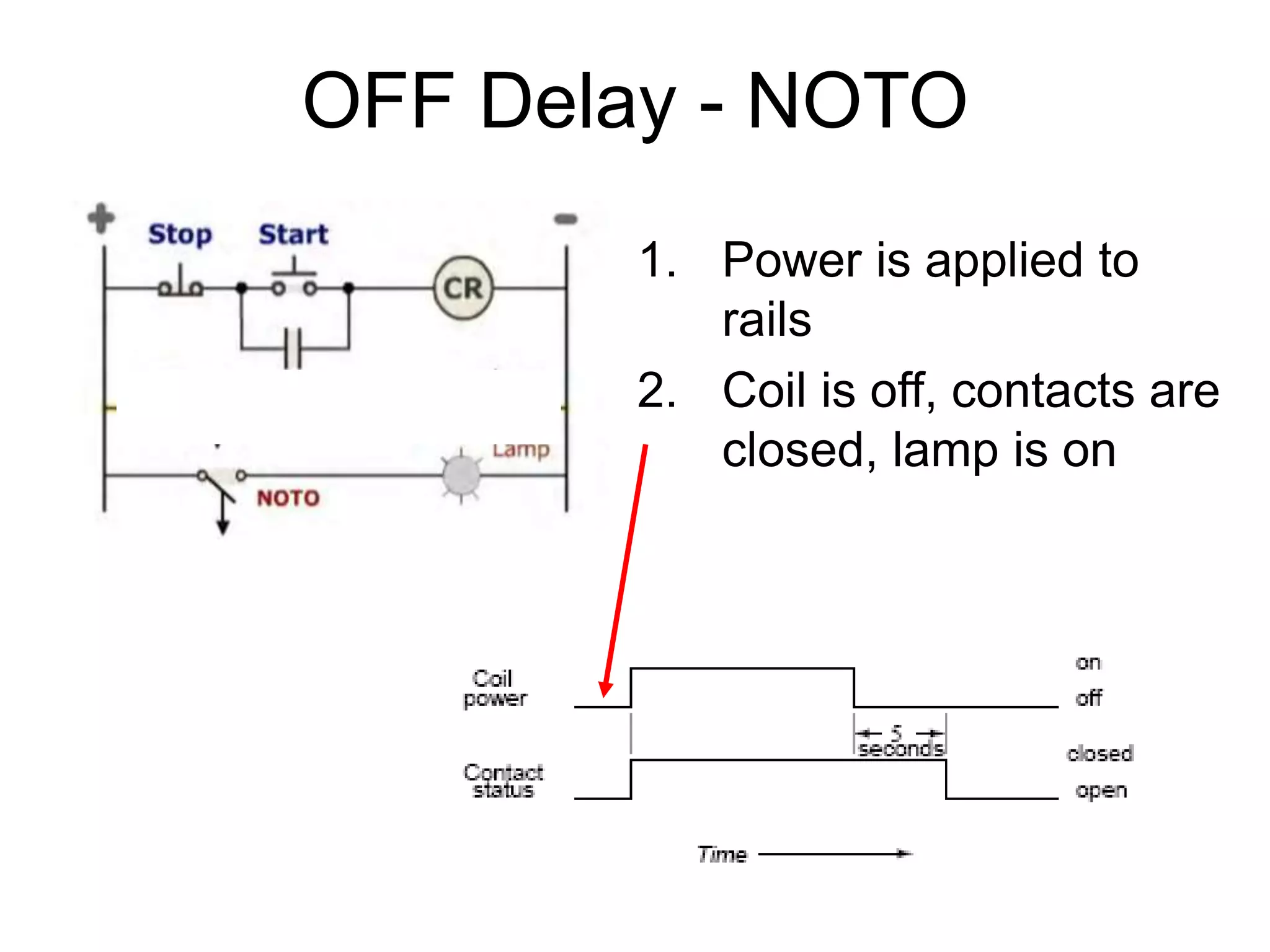
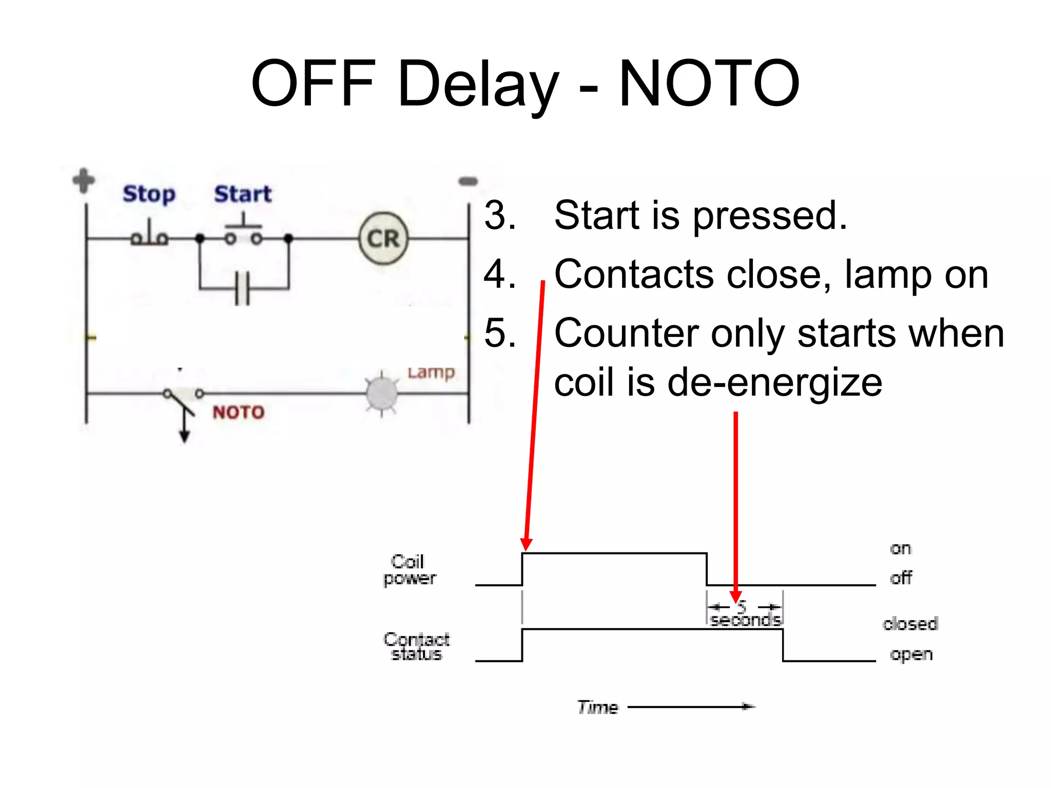
4. Contactors
A Contactor is a control device
that uses a small control
current to energize or de-
energize the load connected
to it.
Abouts:
• A contactor has a frame,
plunger, and a solenoid coil.
• The action of the plunger is
used to close (or open) sets
of contacts.
• A contactor does not include
overload protection.
• The closing of the contacts
allows electrical devices to be
controlled from remote
locations.
6. Magnetic Motor Starters
• A magnetic motor starter is an electrically-
operated switch (contactor) that includes motor
overload protection.
• Magnetic motor starters are identical to
contactors except that they have overloads
attached to them.
• The overloads have heaters or electronic
overloads (located in the power circuit) which
sense excessive current flow to the motor.
• The heaters open the NC overload contacts
(located in the control circuit) when the overload
becomes dangerous to the motor.
8. Magnetic Motor Starter
L1 (1) - first line in from power source (phase
1 for 3ph / Neutral for 1ph)
L2 (3) - second line in from power source
(phase 2 for 3ph / Hot for 1ph* see below
for alternate wiring using L2 & L3)
L3 (5) - third line in from power source (phase
3 for 3ph / NC for for 1ph)
COIL
T1 (2) - first line out to motor (phase 1 for 3ph
/ Hot for 1ph)
T2 (4) - second line out to motor (phase 2 for
3ph / NC for 1ph* see below for alternate
wiring)
T3 (6) - third line out to motor (phase 3 for 3ph
/ Neutral for 1ph)
10. NEMA vs IEC
If we compare the NEMA magnetic motor starter to the IEC
magnetic motor starter, the following differences would
be noticed:
• An IEC device is physically smaller than a comparable
NEMA device.
• An IEC device is usually less expensive than a
comparable NEMA device.
• An IEC device has a life cycle of approximately one
million operations while a comparable NEMA device has
a life cycle of almost four times that number.
• An IEC device should normally be protected with fast-
acting, current-limiting fuses while a NEMA device can
be protected with conventional time delay fuses.
14. Wired ON Delay - NCTO
1. Energy applied to
power rails
2. Start PB is pressed
- Coil is energized
- Holding contact close
- Timer contact stays
closed, lamp stays on.
- Count begins (5 sec)
2
X1 X2ON
NC
NC
ON
15. Wired ON Delay - NCTO
3. Timer count ends
- Coil is still energized
- Timer contact open
- lamp goes off.
4. Timer contacts remain
open until the coil is de-
energized3
X1 X2ON
NO
NC
OFF
The Normally Closed contact will take 5 seconds To Open when the coil is energized.
16. ON Delay - NOTC
1. Power is applied
to rails
X1 X2
The Normally Open contact will take 5 seconds To Close when the coil is energized.
OFF
NO OFF
1
17. ON Delay - NOTC
2. Start PB is pressed
– Coil energizes
– Holding contacts
close
– Timer contacts stay
open
– Lamp stays off
– Counter starts to
count (5 sec)
X1 X2
The Normally Open contact will take 5 seconds To Close when the coil is energized.
ON
NC
OFF
2
18. ON Delay - NOTC
3. Counter finishes count
– Coil stays energized
– Timer contacts close
– Lamp goes on
4. Timer contacts will
open when relay coil
is de-energized.
X1 X2
The Normally Open contact will take 5 seconds To Close when the coil is energized.
ON
NC
ON
3
NC
19. OFF Delay - NCTC
1. Power is applied to
rails
2. Coil is off, contacts are
closed, lamp is on
The timer contacts will close 5 seconds after the coil is de-energized
20. OFF Delay - NCTC
3. Start PB is pressed
4. Timer contacts open
5. Counter will start to
count only when coil is
de-energized.
21. OFF Delay - NOTO
1. Power is applied to
rails
2. Coil is off, contacts are
closed, lamp is on
22. OFF Delay - NOTO
3. Start is pressed.
4. Contacts close, lamp on
5. Counter only starts when
coil is de-energize