Downloaded 24 times

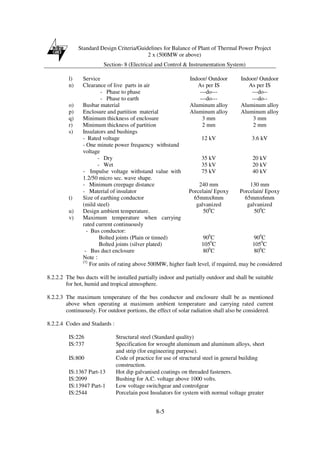
![Standard Design Criteria/Guidelines for Balance of Plant of Thermal Power Project
2 x (500MW or above)
Section- 3 (Ash Handling Plant)
3-30
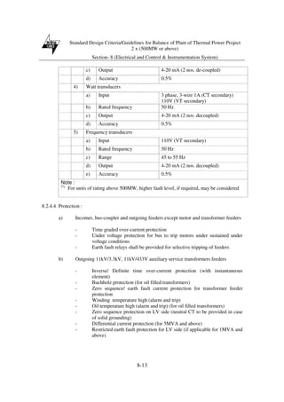
3A.2.7 Common for vacuum and pressure Conveying system
(i) All interconnecting compressed air/exhaust pipelines complete with valves and
fittings and supporting steel structure.
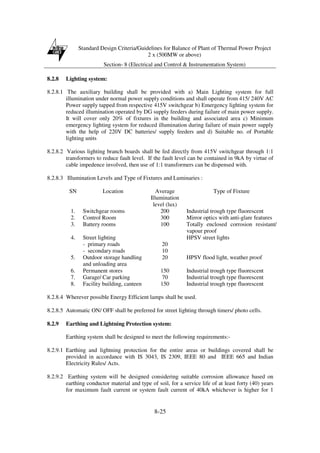
(ii) M.S. Disposal pipes for transfer of slurry from collector tank to fly ash slurry trench
with supporting structures. Fly ash slurry trench shall be provided below collector
tanks to transfer fly ash slurry from collector tanks to slurry sump in the combined
ash slurry pump house as specified and as required.
(iii) Cast iron liners for lining the slurry trench up to ash slurry pump house.
(iv) All nuts, bolts and jointing materials at flanged termination points.
(v) Mechanical ventilation (supply/exhaust fans) for different areas in vacuum/extraction
compressor house and air conditioning of main control room housing DDCMIS based
main control desk.
(vi) One (1) no. pendant controlled electrically operated overhead traveling crane for each
conveying air compressor house as specified complete with runway rails, necessary
rail clamps, bolts, splice bars and stops for each of the runway.
(vii) Two (2) x 100% instrument air compressors for each unit i.e. one (1) working and
one (1) standby, along with its dedicated air drying plants, air receivers complete
with motors, valves, pads and pipelines along with supporting steel structures to meet
the complete requirement of ash handling plant such as actuation of material
handling, segregation valves ; various water and airline valves, slurry valves; bag
filter cleaning etc.
(viii) Two (2) x 100% capacity aeration blowers per unit for aeration upto intermediate
surge hoppers, wetting head/collector tank tower during dry/wet mode of operation,
each complete with dedicated heaters, valves, pipelines including supporting steel
structure, insulation, silencer, filters and all other accessories as specified and as
required.
(ix) Suitable ventilation and lighting system shall be provided for tunnel section of slurry
trench.
3A.2.8 Wet Fly Ash Slurry System
This system shall consist of :
(i) Eight (8) [four (4) working and four (4) stand-by] wetting heads
(ii) Eight (8) [four (4) working and four (4) stand-by] collector tanks
(iii) Eight (8) [four (4) working and four (4) stand-by] air washers.
(iv) One (1) ash slurry line from each collector tank to the common ash slurry sump.](https://image.slidesharecdn.com/standarddesignbopsep10-180318114618/85/Standard-design-bop_sep10-67-320.jpg)


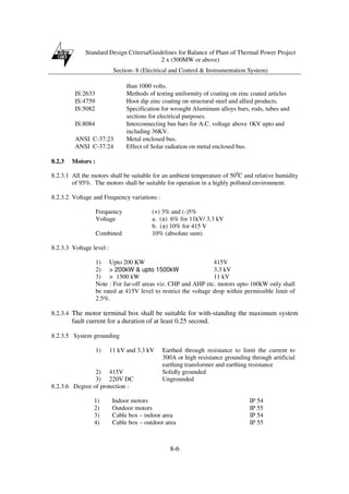
![Standard Design Criteria/Guidelines for Balance of Plant of Thermal Power Project
2 x (500MW or above)
Section- 7 (Fire Protection, Detection And Alarm System)
7-2
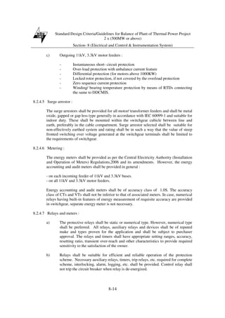
a) Hydrant system
Hydrant system comprises of hydrant pumps (2 motor driven + one diesel engine
driven + one diesel engine driven as standby), pressurization arrangement [2 nos.
motor driven jockey pumps (1 w + 1 standby], water mains network, hydrants
(landing valves, internal hydrants, external hydrants, water monitors), hoses,
instantaneous couplings, etc. Hydrants are located throughout the power station area.
In case of fire, hose is coupled to respective hydrant valves and jets of water are
directed to the fire. Hydrant system is kept pressurized continuously to normal
working pressure.
b) Automatic high velocity water (HVW) & medium velocity water (MVW) spray
system
It consists of spray pumps (1 motor driven main pump + 1 diesel engine standby),
pressurization arrangements, water mains network, wet detection system comprising
QBD, deluge valves, isolation valves, Y-type strainers, spray nozzles/projectors,
spray nozzles piping network, detection & control system, piping, valves, other
accessories etc. The system is automatic and is activated by a dedicated detection
system to be provided for each equipment/area. The system is kept pressurized
continuously to normal working pressure up to the deluge valves.
c) Automatic fixed foam system for fuel oil storage tanks
Automatic fixed foam system is envisaged for main HFO/LSHS and LDO storage
tanks. In case of fire, the foam system for the respective tank gets automatically
activated on detection of fire by probe type heat detectors provided inside the fuel oil
tanks resulting in pouring of the foam water mixture on the oil surface inside the tank
and foam blanketing the burning oil surface thereby cutting the oxygen supply and
extinguishment of fire. The fixed foam system consists of foam concentrate storage
tanks, foam pumps (1W+1S), balancing line with automatic controlling valves, foam
makers, discharge outlets, interconnection piping, valves, fittings instrumentation and
control system. In addition, semi-fixed system consisting of a separate foam solution
ring main around the tank farm area with foam hydrant valves at regular intervals is
also provided.
Water for foam system for main fuel oil and LDO storage tanks and MVW spray for
main LDO storage tank is tapped from nearest hydrant system header.
d) Automatic inert gas system
The inert gas system uses any of the inert gas like, ‘Argon, Nitrogen, Inergen or
Argonite’ as inert gas agent. The system consists of inert gas cylinders filled with
the agent gas, cylinder mounting accessories, cylinder manifold, automatic discharge
valves, discharge piping, nozzles, automatic operating devices, manual actuation
devices/ abort switches, etc. The system is automatic and is activated by a dedicated
detection system to be provided for each hazard area.](https://image.slidesharecdn.com/standarddesignbopsep10-180318114618/85/Standard-design-bop_sep10-143-320.jpg)

This document provides standard design criteria and guidelines for the balance of plant systems for thermal power projects with a capacity of 2 x 500 MW or more. It covers key balance of plant systems including coal handling, ash handling, fuel oil handling, water treatment, circulating water, fire protection, and electrical and instrumentation. The guidelines include descriptions of each system, design criteria, performance requirements, applicable codes and standards, and typical scope of work. The document aims to help utilities in sizing and selecting equipment and preparing detailed specifications tailored to each project site.


