A two-wheeler is statically unstable but as the speed increases vehicle achieves stability. At low speed, the vehicle loses its stability. In order to achieve stability, the driver has to balance the vehicle. While negotiating a curve, a vehicle has to lean to a certain angle, if this angle exceeds the certain value, the vehicle tends to skid. In this paper the stability control system is incorporated, so that a vehicle will maintain stability even at low speeds. The stability of a two-wheeler depends on weight distribution, tyre dynamics, speed and steering angle. In this paper, only two parameters are considered, one is steering effect and another one is speed. For developing a simplified model, the speed of the vehicle is kept as constant, using which the effect of steering angle is analysed and accordingly a controller is incorporated for providing stability.
PNEUMATIC VEHICLE ACTIVE SUSPENSION SYSTEM USING PID CONTROLLERTushar Tambe
The slide contains the simulation of pneumatic active suspension behavior on different road surface. These results shows the active suspension with controllers works effectively,if feedback loop is provided.
Load speed regulation in compliant mechanical transmission systems using feed...ISA Interchange
The problem of controlling the load speed of a mechanical transmission system consisting of a belt- pulley and gear-pair is considered. The system is modeled as two inertia (motor and load) connected by a compliant transmission. If the transmission is assumed to be rigid, then using either the motor or load speed feedback provides the same result. However, with transmission compliance, due to belts or long shafts, the stability characteristics and performance of the closed-loop system are quite different when either motor or load speed feedback is employed. We investigate motor and load speed feedback schemes by utilizing the singular perturbation method. We propose and discuss a control scheme that utilizes both motor and load speed feedback, and design an adaptive feedforward action to reject load torque disturbances. The control algorithms are implemented on an experimental platform that is typically used in roll-to-roll manufacturing and results are shown and discussed.
Mathematical model analysis and control algorithms design based on state feed...hunypink
XZ-Ⅱtype rotary inverted pendulum is a typical mechatronic system; it completes real-time motion control using DSP motion controller and motor torque. In this paper, we recognize XZ-Ⅱrotational inverted pendulum and learn system composition, working principle, using method, precautions and software platform. We master how to build mathematical model and state feedback control method (pole assignment algorithm) of the one order rotational inverted pendulum system and finish simulation study of system using Mat lab. In the end we grasp debugging method of the actual system, and finish online control of the one order rotational inverted pendulum system as well.
Robust composite nonlinear feedback for nonlinear Steer-by-Wire vehicle’s Yaw...journalBEEI
Yaw control is a part of an Active Front Steering (AFS) system, which is used to improve vehicle manoeuvrability. Previously, it has been reported that the yaw rate tracking performance of a linear Steer-by-Wire (SBW) vehicle equipped with a Composite Nonlinear Feedback (CNF) controller and a Disturbance Observer (DOB) is robust with respect to side wind disturbance effects. This paper presents further investigation regarding the robustness of the combination between a CNF and a DOB in a nonlinear environment through a developed 7-DOF nonlinear SBW vehicle. Moreover, in contrast to previous studies, this paper also contributes in presenting the validation works of the proposed control system in a real-time situation using a Hardware-in-Loop (HIL) platform. Simulation and validation results show that the CNF and DOB managed to reduce the influence of the side wind disturbance in nonlinearities.
The report was done to develop a MATLAB model of a suspension system of a 4 wheel vehicle going over an uneven road. A simulink model was developed to simulate the various forces acting on the suspension of the vehicle.
Stabilized controller of a two wheels robotjournalBEEI
The Segway Human Transport (HT) robot, it is dynamical self-balancing robot type. The stability control is an important thing for the Segway robot. It is an indisputable fact that Segway robot is a natural instability framework robot. The case study of the Segway robot focuses on running balance control systems. The roll, pitch, and yaw balance of this robot are obtained by estimating the Kalman Filter with a combination of the pole placement and the Linear Quadratic Regulator (LQR) control method. In our system configuration, the mathematical model of the robot will be proved by Matlab Simulink by modelling of the stabilizing control system of all state variable input. Furthermore, the implementation of this system modelled to the real-time test of the Segway robot. The expected result is by substitute the known parameters from Gyro, Accelero and both rotary encoder to initial stabilize control function, the system will respond to the zero input curve. The coordinate units of displacement response and inclination response pictures are the same. As our expected, the response of the system can reach the zero point position.
The stabilization of forced inverted pendulum via fuzzy controllereSAT Journals
Abstract
In the field of nonlinear control engineering, the inverted pendulum can be considered as a bench mark problem. For an inverted
pendulum, there are mainly two types of equilibrium which are categorized as stable equilibrium and unstable equilibrium. The
stable equilibrium is the one in which the pendulum is in normal pendent position and not requires any control force since
because it is naturally stable. Under the influence of an external force, the stable equilibrium loses its stability and there comes
the need of a stabilizing controller. Therefore unstable equilibrium refers to the pendulum in upright position strictly under the
influence of a stabilizing controller. The inverted pendulum is strictly nonlinear, under actuated system; challenging task comes
with the stability analysis. A forced inverted pendulum is considered which has been modeled with respect to the cart motion. To
improve the performance and stabilize the system, a fuzzy controller is designed for the respective system. Simulation results
validate the fact that the stabilization is achieved through out and the perfect result is obtained for the system.
Keyword: Fuzzy, Heuristic, Forced Inverted Pendulum
Mathematical Modeling and Simulation of Two Degree of Freedom Quarter Car Modelijsrd.com
The proposed study is to develop an active suspension system to increase the comfort for the passenger by reducing the body acceleration. The dynamic quarter car suspension system is considered for mathematical modelling and simulation is carried using MATLAB SIMULINK. The present suspension system is controlled by Proportional- Integral -Derivative controller. The system performance is analysed using the single speed bump road surface and the effectiveness is evaluated with active and passive controlled systems.
This project was developed for an Embedded systems class: we implemented a PID controller for a mechanical inverted pendulum. It was very interesting to experiment in practice with a simple control plant.
Comparative analysis of observer-based LQR and LMI controllers of an inverted...journalBEEI
An inverted pendulum is a multivariable, unstable, nonlinear system that is used as a yardstick in control engineering laboratories to study, verify and confirm innovative control techniques. To implement a simple control algorithm, achieve upright stabilization and precise tracking control under external disturbances constitutes a serious challenge. Observer-based linear quadratic regulator (LQR) controller and linear matrix inequality (LMI) are proposed for the upright stabilization of the system. Simulation studies are performed using step input magnitude, and the results are analyzed. Time response specifications, integral square error (ISE), integral absolute error (IAE) and mean absolute error (MAE) were employed to investigate the performances of the proposed controllers. Based on the comparative analysis, the upright stabilization of the pendulum was achieved within the shortest possible time with both controllers however, the LMI controller exhibits better performances in both stabilization and robustness. Moreover, the LMI control scheme is effective and simple.
Linear Control Technique for Anti-Lock Braking SystemIJERA Editor
Antilock braking systems are used in modern cars to prevent the wheels from locking after brakes are applied. The dynamics of the controller needed for antilock braking system depends on various factors. The vehicle model often is in nonlinear form. Controller needs to provide a controlled torque necessary to maintain optimum value of the wheel slip ratio. The slip ratio is represented in terms of vehicle speed and wheel rotation.
In present work first of all system dynamic equations are explained and a slip ratio is expressed in terms of system variables namely vehicle linear velocity and angular velocity of the wheel. By applying a bias braking force system, response is obtained using Simulink models. Using the linear control strategies like PI-type the effectiveness of maintaining desired slip ratio is tested. It is always observed that a steady state error of 10% occurring in all the control system models.
This paper present a speed hybrid fuzzy-sliding mode control (HFSMC) of a permanent magnet synchronous motor (PMSM) to ensure the traction of an electric vehicle; at the first we applied the sliding mode control (SMC) with three surfaces on the PMSM by taking into account the dynamics of the vehicle; And afterwards we applied the fuzzy-sliding mode in which the surface of the speed is replaced by a Fuzzy-PI controller; Simulation under Matlab/Simulink has been carried out to evaluate the efficiency and robustness of the proposed control on a system drive. It should be noted that the reference speed is the European urban driving schedule ECE-15 cycle.
Design and Analysis of Mechanism for Dynamic Characterization of Power Transm...iosrjce
Power transmission systems are being widely used for transmission of power between two members.
Once a particular transmission system is realized it needs to be qualified before its course of application. As
part of this intended torque of the transmission systems needs to be measured and tested. Conventional means of
dynamic characterization of power transmission system has got the demerit of energy consumption to a greater
extent. Because of this more effort is to be put in terms of power for the sake of testing the intended system.
Great need exists for a system which consumes less or ideally no energy while performing test. This project
aims at evolution of a novel technique for evaluating the torque transmitting capability of power transmission
systems without consuming more energy. To start with all the subsystems of the proposed design will be
identified and each of them will be designed for getting their dimensions. Then these dimensional models will be
transformed to solid model of the assembled configuration using 3D CAD software. Functional load which will
be experienced by this design will be assessed and structural analysis will be carried out against these loads
using Finite Element Method (FEM) in commercial FEA software i.e. ANSYS
This paper describes the design and the simulation of a non-linear controller for two-mass system using induction motor basing on the backstepping method. The aim is to control the speed actual value of load motor matching with the speed reference load motor, moreover, electrical drive’s respone ensuring the “fast, accurate and small overshoot” and reducing the resonance oscillations for two-mass system using induction motor fed by voltage source inveter with ideally control performance of stator current. Backstepping controller uses the non-linear equations of an induction motor and the linear dynamical equations of two-mass system, the Lyapunov analysis and the errors between the real and the desired values. The controller has been implemented in both simulation and hardware-in-the-loop (HIL) real-time experiments using Typhoon HIL 402 system, when the drive system operates at a stable speed (rotor flux is constant) and greater than rated speed (field weakening area). The simulation and HIL results presented the correctness and effectiveness of the controller is proposed; furthermore, compared to PI method to see the response of the system clearly.
Electro-Mechanical Actuator (EMA) is the key
component in the guidance systems of missiles to convert
electrical power into mechanical power. EMAs have shown
significant improvement in response times and are more reliable
compared to other actuators. This paper proposes a Simulink
model for a linear electromechanical actuator which is very efficient
and can withstand noise and disturbances. Electromechanical
actuators are mechanical actuators where the control handle has
been supplanted by an electric motor. This model is subjected to
sudden loads and disturbances and the precise actuation is
obtained within the specified settling time. The model is also
subjected to nonlinearities and the results were found out to be
competent.
We focus a modern methodology in this paper for adding the fuzzy logic control as well as sliding model control. This combination can enhance the MLS position control robustness and enhanced performance of it.In the start, for an application in an area to control the loops placement and position for the synchronous motor what has permanent magnetic linearity we tend to control the fuzzy sliding mode control. To resolve the chattering issues a designed controller is investigated and, in this way, steady state motion in sliding with higher accuracy is obtained. In this case, method of online tuning with the help of fuzzy logic is used in order to adjust the thickness of boundary layer and switching gains.For the suggested scheme technique, the outcomes of simulation suggest that with the classical SMC the accurate state and good dynamic performance is compared due to force chattering resistance, response by quick dynamic force and external disturbance elements and robustness against them.
Suspension system is the most significant part which heavily affects the vehicle handling performance and ride quality. Because of its structures limit, the passive suspension system can hardly improve the two properties at the same time. Since the advent of active suspension system, it has become the research hot spot. In this review paper we shall see the advantages of the active suspension system over the passive suspensions systems and its incorporation in passenger vehicles.
Hardware-in-the-loop based comparative analysis of speed controllers for a tw...journalBEEI
A comparative study of speed control performance of an induction motor drive system connecting to a load via a non-rigid shaft. The nonrigidity of the coupling is represented by stiffness and damping coefficients deteriorating speed regulating operations of the system and can be regarded as a two-mass system. In the paper, the ability of flatness based and backstepping controls in control the two-mass system is verified through comprehensive hardware-in-the-loop experiments and with the assumption of ideal stator current loop performance. Step-by-step control design procedures are given, in addition, system responses with classical PID control are also provided for parallel comparisons.
MODELLING SIMULATION AND CONTROL OF AN ACTIVE SUSPENSION SYSTEM IAEME Publication
Conventional passive suspension systems lag in providing the optimum level of performance. Passive suspensions are a trade-off between the conflicting demands of comfort and control. An active suspension system provides both comfort and control along with active roll and pitch control during cornering and braking. Thus it gives a ride that is level and bump free over an incredibly rough terrain. This paper is a review the active suspension system and the modelling, simulation and control of an active suspension system in MATLAB/Simulink. The performance of the system is
determined by computer simulation in MATLAB/Simulink. The performance of the system can be controlled and improved by proper tuning a proportional-integral-derivative (PID) controller.
Modeling and simulation of vehicle windshield wiper system using h infinity l...Mustefa Jibril
Vehicle windshield wiper system increases the driving safety by contributing a clear shot viewing to the
driver. In this paper, modelling, designing and simulation of a vehicle windshield wiper system with robust control
theory is done successfully. H loop shaping and robust pole placement controllers are used to improve the
wiping speed by tracking a reference speed signals. The reference speed signals used in this paper are step and sine
wave signals. Comparison of the H loop shaping and robust pole placement controllers based on the two
reference signals is done and convincing results have been obtained. Finally the comparative results prove the
effectiveness of the proposed H Loop Shaping controller to improve the wiping mechanism for the given two
reference signals.
Servomotor based electronic steering system in four wheeler vehicles by means...eSAT Journals
Abstract
In Olden Days Steering Mechanisms Developed To Turn A Vehicle At A Certain Radius While Negotiating A Turn Had A Greater
Steering Gear Ratio. For A Small Rotation Of The Steering Gear The Steering Wheel Had To Be Given A Greater Effort For
Larger Degree Of Rotation Than That Of The Steering Gear Inorder To Develop Torque For Turning The Vehicle. To Reduce The
Effort At The Steering Wheel, Power Steering Was Developed In The 18th Century. It Not Only Made Steering Easier But Also
Increased The Accuracy In Steering A Four Wheeled Vehicle. Precision Turning In Four Wheeled Vehicles Not Only Prevents The
Vehicle From Skidding But Also Prevents Road Accidents. Various Other Mechanisms Were Also Established For Reducing The
Steering Effort And Precision Turning Including Hydraulics As Well As Electronic Type. Taking Into Account The Various
Systems Of Steering As Well As Using A Bit Of Electronics And Microcontroller Application A Modern Technique Can Be
Developed Using A Servomotor, An Accelerometer And A Microprocessor For An Increased Precision In Steering Of A Vehicle
Which May Be Termed As The “Accelerometer Driven Servomotor Based Steering Gear” Or “A.S. Steering Gear”. In This
Paper, I Shall Discuss How To Use An Accelerometer To Control A Servomotor Inorder To Help In Steering Of A Vehicle By
Means Of Basic Microcontroller Applications And Programming.
Keywords— Servomotor, Accelerometer, Fundamental Law Of Correct Gearing, Steering Gear Ratio,
Microprocessor, Analog To Digital Conversion, Pulse Width Modulation, Rack And Pinion Assembly
Design and Simulation of Different Controllers for Stabilizing Inverted Pendu...IJERA Editor
The Inverted Pendulum system has been identified for implementing controllers as it is an inherently unstable system having nonlinear dynamics. The system has fewer control inputs than degrees of freedom which makes it fall under the class of under-actuated systems. It makes the control task more challenging making the inverted pendulum system a classical benchmark for the design, testing, evaluating and comparing. The inverted pendulum to be discussed in this paper is an inverted pendulum mounted on a motor driven cart. The aim is to stabilize the system such that the position of the cart on the track is controlled quickly and accurately so that the pendulum is always erected in its vertical position. In this paper the linearized model was obtained by Jacobian matrix method. The Matlab-Simulink models have been developed for simulation for optimal control design of nonlinear inverted pendulum-cart dynamic system using different control methods. The methods discussed in this paper are a double Proportional-Integral-Derivative (PID) control method, a modern Linear Quadratic Regulator (LQR) control method and a combination of PID and Linear Quadratic Regulator (LQR) control methods. The dynamic and steady state performance are investigated and compared for the above controllers.
Stability analysis of a Rigid Vehicle Modelsaeid ghaffari
The lateral stability of a two axle vehicle with open loop control will be studied in this project. A 3 dof model is adopted to evaluate the curvature gain and the root loci as a function of the vehicle speed V. Moreover, the dynamic response of the vehicle considering the step steer manoeuvre will be analysed according to the ISO norm. The side slip angle and the yaw rate are evaluated as a function of time, while the trajectory of the center of gravity G of the vehicle with respect to the inertial reference frame (OXY Z) is plotted during step steer maneuver. Inasmuch as the change of cornering stiffness on tires due to the different condition are small, we cannot see the difference between the trajectories, shedding light on the steering angles, however, we can understand what is happening in various conditions. In this study, both the effect of traction force on the front and rear axle and transversal load transfer on the front and rear axle are investigated.
*only the first 10 pages of the main project are presented here. If you are interested to go through the rest of this document please contact me via saeid.ghaffari@studenti.polito.it.
Comparative Analysis of Multiple Controllers for Semi-Active Suspension SystemPrashantkumar R
International Conference on Emerging Research in Computing, Information, Communication and Applications, ERCICA 2014, held on 01-02 Aug 2014 in Nitte Meenakhsi Institute of Technology, Bangalore, India
Paper ID: 600
Navigation of Mobile Inverted Pendulum via Wireless control using LQR TechniqueIJMTST Journal
Mobile Inverted Pendulum (MIP) is a non-linear robotic system. Basically it is a Self-balancing robot
working on the principle of Inverted pendulum, which is a two wheel vehicle, balances itself up in the vertical
position with reference to the ground. It has four configuration variables (Cart position, Cart Velocity,
Pendulum angle, Pendulum angular velocity) to be controlled using only two control inputs. Hence it is an
Under-actuated system. This paper focuses on control of translational acceleration and deceleration of the
MIP in a dynamically reasonable manner using LQR technique. The body angle and MIP displacement are
controlled to maintain reference states where the MIP is statically unstable but dynamically stable which
leads to a constant translational acceleration due to instability of the vehicle. In this proposal, the
implementation of self balancing robot with LQR control strategy and the implementation of navigation
control of the bot using a wireless module is done. The simulation results were compared between PID control
and LQR control strategies.
The formula cars need high tire grip on racing challenge by reducing rolling displacement at corner or
double change lands. In this case study, the paper clarifies some issues related to suspension system with
inerter to reduce displacement and rolling angle under impact from road disturbance on Formula SAE
Car. We propose some new designs, which have an advance for suspension system by improving dynamics.
We optimize design of model based on the minimization of cost functions for roll dynamics, by reducing the
displacement transfer and the energy consumed by the inerter. Base on a passive suspension model that we
carried out quarter-car and half-car model for different parameters which show the benefit of the inerter.
The important advantage of the proposed solution is its integration a new mechanism, the inerter, this
system can increase advance in development and have effects on the vehicle dynamics in stability vehicle.
GM Distributed Generation Inverters in a Micro grid by Controlling Energy Man...IOSRJEEE
This project introduces a micro grid, which consists of different distributed generation units which are connected to the distribution grid. The operations of the DG units are coordinated by the power management algorithm in grid and islanded operations. The primary generation unit of the micro grid is the wind turbine and the proton exchange membrane fuel cell is used to supplement the variability in the power. In micro grid a battery is incorporated to overcome the difficulty of shortage of power demand during Islanded operation and to improve crest demands throughout grid connected operation. Previously the power management system was done using model predictive algorithm control design. Which has complex mathematical calculations to find out critical values Now in this project, ANFIS controller is used as the control design which reduces the design complexity as the logical operations are performed to find out critical values, the power quality such as harmonic compensation for nonlinear loads of the distribution system, will be improved when compared to model predictive algorithm control design and also It has fast response. The complete proposed system will be tested using MATLAB/SIMULINK and the simulation results reveal the attractive performance characteristics of the proposed system.
Load Performances of a PIC Based Speed Governor for Micro Hydro Power PlantIOSRJEEE
In the study; a micro hydro power plant prototype was designed with a 750 Wcross flow type turbine and a 500 W generator. Control operations are realized by using a PIC16F877 microcontroller. The voltage frequency obtained from the generator were measured with the zero crossing circuit and transferred to the microcontroller. Using the micro controller, depending on the frequency error, the PWM signal was formed. The PWM signal was applied through the H bridge circuit to the DC motor which drives the setting wing. The rotation movement of the motor was transferred to the setting wing through a threaded rod and a mechanical arm. When setting of the number of turns on the turbine, the value of the frequency of the used 500 W generator working in conjunction with the turbine could be kept on desired levels. After the design,Loading and load shedding performances of the designed system were examined and discussed.
A New Design in Parabolic Trough Using Heat RetentionIOSRJEEE
The paper gives the summary of new design of parabolic trough using heat retention method. It gives a brief idea of on heat retention and describes about the components and operation of parabolic trough. This is an updating of parabolic trough collector system. The advantages collectors are also discussed
Investigation of Power Quality Indices in Jordanian Distribution GridIOSRJEEE
he sensitivity and the highly connected modern power systems make Power quality problems a priority in these systems. Both utilities and consumers have essential role in dealing with these problems. It is utilities responsibility to provide a clean and reliable power. On the other hand, it is consumer’s responsibility to draw power with acceptable indices. In this Paper, the type of the consumer’s facility is chosen as a basis for managing power quality indices. In this paper, comprehensive power quality in Jordan Low-Voltage Electrical Power Grid is measured. The loads are divided into five categories: : (i) industrial loads, (ii) commercial loads, (iii) hospital loads, (iv) residential loads, and (v) office loads. Assuming each category will affect the grid in similar way, which will facilitate prediction of power quality problems. Also, this methodology will help proposing new regulation that governs the relation between utilities and consumers. The power quality indices considered in this paper are; THD, Crest factor, K-factor, Power factor, Harmonic to active power ratio, Voltage imbalance, and Frequency variations. The results show similar results for the loads with the same type. Also, the results show the correlation between the current total harmonic distortion and utility voltages and neutral-to-ground voltage, and between voltage and current imbalance.
Improving Distribution System Performance in Deregulated Electricity Industry...IOSRJEEE
In many developing countries, domestic electricity consumers having single phase appliances are most times supplied with single phase meters with incoming three phase supply lines. Due to frequent phase faults, these customers often change their supply from one phase to another whenever there is low voltage or no supply in the phase they are currently connected to. This action coupled with the fact that there is uneven distribution of loads on the distribution transformers in residential areas, lead to more transformer overload with consequential loss of power, equipment, man-hours, revenue and in extreme cases, life. When electricity was treated as a welfare commodity or as part of government social responsibility, these consequences where ignored. But with commercialization, privatization and deregulation, cost minimization and profit maximization have become the watchwords. As a means of minimizing this, utilizing the concept of phase-constrained electricity billing scheme in the deregulated Nigerian Power Industry was presented in this work. The phaseconstrained billing model involves re-arranging the service lines and setting up constraint matrices to relate the phase and service lines utilizable by customer to the electricity bill using penalty factors. To test the acceptability of this model, a customer behavior and utilization index based questionnaires were administered in the field. The survey was analyzed using the statistical attitude measurement technique based on the 5-point Likert Scale. The responses obtained showed that introducing a penalty factor in the billing which ensure that those using more phases pay higher will minimize frequent change of phases; and provide a direction for utilities and customers in resolving the power quality and availability problems associated with frequent phase changing.
High Efficiency Dc-Dc Converter for Renewable Energy Applications and High Vo...IOSRJEEE
Renewable sources like solar PV cell is prefer to be operated at low voltages. This paper proposes a novel high voltage gain, high efficiency dc-dc converter based on coupled inductor, intermediate capacitor. The input energy acquired from the source is first stored in the coupled inductor and intermediate capacitor in a lossless manner. Improve the voltage gain and efficiency of the system. Exorbitant duty cycle values are not required for high voltage gain, when prevent the problems such as diode reverse recovery. Presence of a passive clamp network causes reduced voltage stress on the switch. Overall performance of the renewable energy with a step-up DC/DC converter using closed loop control action is used in the proposed system, improving the overall efficiency of the system.
Performance Indicators For Grid-Connected PV Systems: A Case Study In Casabla...IOSRJEEE
The main goal of this paper is to compare a one year performance of 5.94 KWp grid-connected PV module technology systems, constituted by three types of photovoltaic solar panels (Monocrystalline (mc-Si) (2.04KWp), polycrystalline (pc-Si) (2.04KWp) and amorphous (a-Si) (1.86 KWp))-silicon installed on the roof of the faculty of science Ben M’sik Casablanca. The study is based on the data collected along 2 years (2015- 2016) about energy production. The elements of performance evaluated monthly and annually include: energy output, system efficiency, reference yield, final yield, performance ratio, annual capacity factor and CO2 emissions avoided. The investigation of the annual: productivity (EAC,Y), system efficiency (Ƞ푠푦푠 ,푌 ), performance ratio (PR), capacity factor (CF) and amount of CO2 emissions avoided for a-Si are found as 2941.15KWh, 7.21%, 73.1%, 18.05% and 1.765tonsrespectively. EAC,Y, Ƞ푠푦푠,푌 , PR, CF and amount of CO2 emissions avoided for pc-Si are found as 3331.15KWh, 11.4%, 75.6%, 18.64% and 1.999tons respectively. Mc-Si installation exhibits slightly higher values of EAC,Y, Ƞ푠푦푠 ,푌 , PR, CF and amount of CO2 emissions avoided which are 3370.89KWh, 11.7%, 76.7%, 18.86% and 2.023tons respectively. The results show that mc-Si system presents the best performance followed by pc-Si and by a-Si. In addition, a developed study was carried out to establish the relation between the efficiency and temperature, performance ratios and radiation, in order to know the behavior of each technology for each period of the year and for the whole year. Without forgetting a comparison of all results found with the previous studies in different locations.
A Review of Gas Sensors Based on Semiconducting Metal OxideIOSRJEEE
This study intends to provide a review of recent progress in gas sensors based on several theoretical and empirical investigations regarding semiconducting metal oxide nanostructures. Modified or doped oxide nano-wires, device structures such as electronic noses and low power consumption self-heated gas sensors, and their gas sensing performance has also been evaluate. Finally, the researcher also point out some challenges for prospect investigation and practical application.
Voltage Sag and Swell Identification Using FFT Analysis and Mitigation with DVRIOSRJEEE
- Power quality issues like voltage sag, swell, harmonics and transients can affect the power system performance. Voltage sag and swell are now-a-days treated to reduce power quality issues by power engineers. A small variation in voltage can badly affect the operation of power system and connected loads as well. This paper presents the voltage sag and voltage swell identification using FFT analysis. The paper also presents the mitigation for identified voltage sag and swells issues addressed with DVR. DVR consists of a voltage source converter and is controlled with d-q theory which is simple producing reference signals and gate pulses for switches of DVR. The proposed concept was simulated using MATLAB/SIMULINK software and results were presented for identification and mitigation. FFT analyses for identification of voltage sags and swell existence in different phases of power system network were shown. Mitigation of voltage sag and swell with DVR was also shown with results
Design of Intrusion Tolerance System based on Service Redundancy LevelIOSRJEEE
The Internet is an open space where a great number of computer systems are connected. Since many services are provided through the Internet, malicious users can easily intrude on any of those systems by using the vulnerabilities of the Internet. Although Intrusion Detection and Prevention System (IDPS) can be used to defend against such malicious activities, it is not always possible to completely protect a targeted system against the attacks. For this reason, Intrusion Tolerance Systems (ITS) has been proposed to maintain services even in threatening environments, where some malicious attacks have intruded into a system successfully. In this paper, we propose a new ITS based upon maintaining a service redundancy level to ensure that all services are properly provided to users even if a malicious intrusions such as VM (virtual machine) escape attack exists. The simulation results show that the proposed scheme can guarantee the operation of every ongoing service by maintaining the service redundancy level of all services
Compensation of Harmonics of Fully Controlled Loads by Using SAHFIOSRJEEE
In this paper, Three Phase Shunt Active Harmonic Filter is used for harmonic compensation of fully Controlled loads by using new thyristorized Pulse Generator Circuits which generates 12 Pulses for two NonLinear three phase Loads. The three phase Non-Linear Loads are connected at the secondary of three phase Transformers with Three Phase Breakers having Transition time 5/60seconds. A new Pulse Generator topology is used for generating pulses for each of three phase non-linear loads. The Circuit used for Compensation of Harmonics having three phase IGBT based Inverter. The IGBT base d Shunt Active Harmonic Filter gets firing Pulses from PLL phase Locked Loop& Hysteresis Switching HS. The used PLL extracts the Fundamental component of load current which is then multiplied with same RMS gain for generating the Reference current for Hysteresis Current Controller. The used Hysteresis Current Controller compares the reference current
Design of Half Bridge LLC Resonant Converter for Low Voltage Dc ApplicationsIOSRJEEE
An advanced hybrid LLC series resonant converter with united flying-capacitor cell is proposed in this paper to permit the high step-down conversion in the high input voltage applications. The in-built flyingcapacitor branch in the primary side can efficiently share out the primary switch voltage stress related with the half-bridge LLC converters. And the input voltage can be shared correspondingly and automatically between the two series half-bridge components lacking additional balance circuit or control strategies owing to the built-in flying- capacitor cell. Likewise, the inherent soft switching performance in extensive load range that exists in the LLC converters is still kept to decrease the switching losses, which ensures the high efficiency. In addition, the proposed converter can be comprehensive to reduce the switch voltage stress byemploying stacked connection. Finally, a 500∼640 Vinput 48 Voutput 1 kW prototype is built and tested to verify the efficiency of the proposed converter. The results prove that the proposed converter is an excellent candidate for the high input voltage and high step-down dc/dc conversion systems.
Design of the Pulse Oximetry Measurement Circuit and Its Sensing System Based...IOSRJEEE
The pulse oximetry circuit and its sensing system is designed based on the standard CMOS technology of 0.18um. The reflection oxygen sensor is used to collect the pulse oximeter signal of human body, then the collected physiological signals are processed by the data processing circuit The data processing circuit is composed of two parts: the amplifying circuit and the band-pass filter circuit, and the pulse oximeter data processed by the data processing circuit is written into the tag through the SPI communication The RFID reader read the data in the RFID tag through wireless communication, and display the data . The experimental results show that the maximum error is ±1%. The maximum error of the pulse is ±1.9%. The stability and feasibility of pulse blood oxygen sensing system is demonstrated in this paper and it will have a good application prospect in the direction of wearable medical wisdom research
Design of an Integrated Power Factor Converter with PI Controller for Low Pow...IOSRJEEE
In this paper, an integrated power factor converter with PI controller is proposed. The circuit topology is obtained by integrating two converters namely the buck converter and a boost converter. The boost converter is normally a step up converter which obtain an unity power factor and performs low harmonics at the input. Based on the simple circuit topology and easy control the boost converter or buck-boost converter is used as power factor correctors. Similarly the buck converter regulates the dc-link voltage and provide a stable dc output voltage. To achieve unity power factor, the output voltage of both converter should be higher than the amplitude of the ac line voltage. The steady -state analysis is developed and a design is provided
Magneto Optic Current Transformer Technology (MOCT)IOSRJEEE
An accurate electric current transducer is a key component of any power system instrumentation. To measure currents power stations and substations conventionally employ inductive type current transformers .For high voltage applications, porcelain insulators and oil-impregnated materials have to be used to produce insulation between the primary bus and the secondary windings. The insulation structure has to be designed carefully to avoid electric field stresses, which could eventually cause insulation breakdown. The electric current path of the primary bus has to be designed properly to minimize the mechanical forces on the primary conductors for through faults. The reliability of conventional high-voltage current transformers have been questioned because of their violent destructive failures which caused fires and impact damage to adjacent apparatus in the switchyards, electric damage to relays, and power service disruptions. In addition to the concerns, with the computer control techniques and digital protection devices being introduced into power systems, the conventional current transformers have caused further difficulties, as they introduce electromagnetic interference through the ground loop into the digital systems. Magneto-optical current transformer(MOCT)technology provides a solution for many of the above mentioned problems. The MOCT measures the electric current by means of Faraday Effect that is the orientation of polarized light rotates under the influence of the magnetic fields and the rotation angle is proportional to the strength of the magnetic field component in the direction of optical path. MOCT is a passive optical current transducer which uses light to accurately measure current on high voltage systems and determines the rotation angle & converts it into a signal of few volts proportional to the current
On Essentiality of RoHS in EE R&D EcosystemIOSRJEEE
Sustainable development demands environmentally friendly products and hence Research and Development ecosystem needs to adopt environmental compliances. This fact is truer for Electrical and Electronics products as its new product launch rate is very high which also produces high rate of obsolescence and hence e-waste. In India one of the environmental standards is RoHS and in this review a case has been presented for early adoption of the compliance in Indian Research and Development ecosystem through modified Nair’s Product Development Cycle. Advantages of early adoption are avoidance of repetition of expected pollution from e-waste again in future, preventing health issues among researchers who handle such substances and improvement of industry confidence on the pre-competitive R&D. Finally RoHS2 instead of RoHS1 has been recommended for adoption to prevent rejection of developed product in future
A high stable on-chip CMOS temperature sensorIOSRJEEE
A high stable CMOS temperature sensor is presented. A low-pass filter circuit is added in the output of traditional CMOS temperature sensor to improve the stability of its output,. The supply power voltage of the temperature sensor is 1.8V. The PSRR of the temperature sensor is -82dB in low frequency state. And the PSRR is -45dB in worst case. The OP-AMP of sensor has 63º phase margin. The output mode is voltage, whose linearity error is less than 0.2% and resolution ratio is more than 2.6mV/℃
Improvement of Load Power Factor by Using CapacitorIOSRJEEE
Series and parallel capacitors in the power system effect reactive power to improve power factor and voltage because of increasing the system capacity and reducing losses. Reactive power of series capacitor is the same to the current. There are certain unpleasant aspects in the capacitor series. Generally, the cost to install a series capacitor is higher than parallel capacitor. It is caused by complex protection equipment for series capacitor and designing series capacitors for greater power than parallel capacitor to solve the future cost. Installation of capacitors is important to reduce of a system reactive power. Transmission line would be most economical if it is used to send active power where the need of reactive power can be obtained by distribution system in substation level. This will allow user in optimum transmission line, improve operational performance and reduce energy losses. It requires a system and planning carefully to fulfill the need of system reactive power in the same way with active power planning and it is programmed an additional generator capacity.
Modeling and Simulation of Three Phase Induction Machine Using Written Pole T...IOSRJEEE
Three phase induction motors are employed in almost all the industries because of its simple construction and easy operation. Efficiency of the induction motor is affected by its fixed losses and variable losses which mainly depend on the input supply voltage and load current respectively. An attempt is made to minimize the iron losses by using the permanent magnet ferrite. A new Three Phase Induction Motor Using Written Pole Technology is proposed in this paper in which stator consists of two three phase windings accommodated in the same stator core and rotor is used as squirrel cage rotor with ferrite material on its periphery. Shaft loads are categorized as low, medium and high, Stator coils are energized through a controller based on the load demand. In this study, it is suggested to operate the machine with flat efficiency characteristics, irrespective of shaft load. When compared to conventional induction motor, the motor efficiency and power factor are improved. Another approach of this machine is that the ferrite layer on the rotor periphery will reduce the motor losses which results in improving the motor efficiency. In this motor, one windings (main winding) is designed for the 238 volt ac voltage while the second winding (exciter winding) is designed for 8 volt high frequency ac voltage. Experimental result ensures the considerable increase in the efficiency and power factor. The aim of this paper is to analyze and simulate performance of a 1Hp three phase induction motor using written pole technology using the well known Park’s transformation. A three phase squirrel cage machine is reconfigured and modeled into a two three phase stator winding accommodate in same stator core of the same volume as the three phase machine. Different tests are carried out on the novel machine to determine machine parameters. Simulation results, that predicts the dynamic performance of the machine using ANSYS, at start up are presented and discussed.
Design of LED Driver Power Based on LNK417EGIOSRJEEE
In recent years, people have been committed to the development and the design of new lighting sources. The life of LED lamps depends on the life of the LED driver which has a great relationship with the life of the electrolytic capacitor. In this paper the advantages of the drive power of the electrolytic capacitor are analyzed and the design of the PFC circuit and the transformer is described in details. On the basis of the LNK417 driver chip, a novel single-stage flyback drive circuit without the electrolytic capacitor is designed, which combines the power factor correction technology and constant current control to avoid the use of large electrolytic capacitors. The design and implementation of the control circuit are given and the overall performance is tested and analyzed in the article. The test results show that the driver is of high efficiency, high PF and long life etc. The efficiency is up to 85% and the PF value is not less than 0.9.
Saudi Arabia stands as a titan in the global energy landscape, renowned for its abundant oil and gas resources. It's the largest exporter of petroleum and holds some of the world's most significant reserves. Let's delve into the top 10 oil and gas projects shaping Saudi Arabia's energy future in 2024.
Overview of the fundamental roles in Hydropower generation and the components involved in wider Electrical Engineering.
This paper presents the design and construction of hydroelectric dams from the hydrologist’s survey of the valley before construction, all aspects and involved disciplines, fluid dynamics, structural engineering, generation and mains frequency regulation to the very transmission of power through the network in the United Kingdom.
Author: Robbie Edward Sayers
Collaborators and co editors: Charlie Sims and Connor Healey.
(C) 2024 Robbie E. Sayers
Industrial Training at Shahjalal Fertilizer Company Limited (SFCL)MdTanvirMahtab2
This presentation is about the working procedure of Shahjalal Fertilizer Company Limited (SFCL). A Govt. owned Company of Bangladesh Chemical Industries Corporation under Ministry of Industries.
COLLEGE BUS MANAGEMENT SYSTEM PROJECT REPORT.pdfKamal Acharya
The College Bus Management system is completely developed by Visual Basic .NET Version. The application is connect with most secured database language MS SQL Server. The application is develop by using best combination of front-end and back-end languages. The application is totally design like flat user interface. This flat user interface is more attractive user interface in 2017. The application is gives more important to the system functionality. The application is to manage the student’s details, driver’s details, bus details, bus route details, bus fees details and more. The application has only one unit for admin. The admin can manage the entire application. The admin can login into the application by using username and password of the admin. The application is develop for big and small colleges. It is more user friendly for non-computer person. Even they can easily learn how to manage the application within hours. The application is more secure by the admin. The system will give an effective output for the VB.Net and SQL Server given as input to the system. The compiled java program given as input to the system, after scanning the program will generate different reports. The application generates the report for users. The admin can view and download the report of the data. The application deliver the excel format reports. Because, excel formatted reports is very easy to understand the income and expense of the college bus. This application is mainly develop for windows operating system users. In 2017, 73% of people enterprises are using windows operating system. So the application will easily install for all the windows operating system users. The application-developed size is very low. The application consumes very low space in disk. Therefore, the user can allocate very minimum local disk space for this application.
Cosmetic shop management system project report.pdfKamal Acharya
Buying new cosmetic products is difficult. It can even be scary for those who have sensitive skin and are prone to skin trouble. The information needed to alleviate this problem is on the back of each product, but it's thought to interpret those ingredient lists unless you have a background in chemistry.
Instead of buying and hoping for the best, we can use data science to help us predict which products may be good fits for us. It includes various function programs to do the above mentioned tasks.
Data file handling has been effectively used in the program.
The automated cosmetic shop management system should deal with the automation of general workflow and administration process of the shop. The main processes of the system focus on customer's request where the system is able to search the most appropriate products and deliver it to the customers. It should help the employees to quickly identify the list of cosmetic product that have reached the minimum quantity and also keep a track of expired date for each cosmetic product. It should help the employees to find the rack number in which the product is placed.It is also Faster and more efficient way.
Quality defects in TMT Bars, Possible causes and Potential Solutions.PrashantGoswami42
Maintaining high-quality standards in the production of TMT bars is crucial for ensuring structural integrity in construction. Addressing common defects through careful monitoring, standardized processes, and advanced technology can significantly improve the quality of TMT bars. Continuous training and adherence to quality control measures will also play a pivotal role in minimizing these defects.
Democratizing Fuzzing at Scale by Abhishek Aryaabh.arya
Presented at NUS: Fuzzing and Software Security Summer School 2024
This keynote talks about the democratization of fuzzing at scale, highlighting the collaboration between open source communities, academia, and industry to advance the field of fuzzing. It delves into the history of fuzzing, the development of scalable fuzzing platforms, and the empowerment of community-driven research. The talk will further discuss recent advancements leveraging AI/ML and offer insights into the future evolution of the fuzzing landscape.
About
Indigenized remote control interface card suitable for MAFI system CCR equipment. Compatible for IDM8000 CCR. Backplane mounted serial and TCP/Ethernet communication module for CCR remote access. IDM 8000 CCR remote control on serial and TCP protocol.
• Remote control: Parallel or serial interface.
• Compatible with MAFI CCR system.
• Compatible with IDM8000 CCR.
• Compatible with Backplane mount serial communication.
• Compatible with commercial and Defence aviation CCR system.
• Remote control system for accessing CCR and allied system over serial or TCP.
• Indigenized local Support/presence in India.
• Easy in configuration using DIP switches.
Technical Specifications
Indigenized remote control interface card suitable for MAFI system CCR equipment. Compatible for IDM8000 CCR. Backplane mounted serial and TCP/Ethernet communication module for CCR remote access. IDM 8000 CCR remote control on serial and TCP protocol.
Key Features
Indigenized remote control interface card suitable for MAFI system CCR equipment. Compatible for IDM8000 CCR. Backplane mounted serial and TCP/Ethernet communication module for CCR remote access. IDM 8000 CCR remote control on serial and TCP protocol.
• Remote control: Parallel or serial interface
• Compatible with MAFI CCR system
• Copatiable with IDM8000 CCR
• Compatible with Backplane mount serial communication.
• Compatible with commercial and Defence aviation CCR system.
• Remote control system for accessing CCR and allied system over serial or TCP.
• Indigenized local Support/presence in India.
Application
• Remote control: Parallel or serial interface.
• Compatible with MAFI CCR system.
• Compatible with IDM8000 CCR.
• Compatible with Backplane mount serial communication.
• Compatible with commercial and Defence aviation CCR system.
• Remote control system for accessing CCR and allied system over serial or TCP.
• Indigenized local Support/presence in India.
• Easy in configuration using DIP switches.
Student information management system project report ii.pdfKamal Acharya
Our project explains about the student management. This project mainly explains the various actions related to student details. This project shows some ease in adding, editing and deleting the student details. It also provides a less time consuming process for viewing, adding, editing and deleting the marks of the students.
Student information management system project report ii.pdf
Stability Control System for a Two-Wheeler
1. IOSR Journal of Electrical and Electronics Engineering (IOSR-JEEE)
e-ISSN: 2278-1676,p-ISSN: 2320-3331, Volume 12, Issue 2 Ver. I (Mar. – Apr. 2017), PP 41-46
www.iosrjournals.org
DOI: 10.9790/1676-1202014146 www.iosrjournals.org 41 | Page
Stability Control System for a Two-Wheeler
1
Niveditha. K, Final year student, 2
Nitta Rani. S, Final year student,
3
Nivedha. S, Final year student, 4
Prof. AL. Kumarappan, Head of the
Department,
1,2,3,4
Department of Electrical and Electronics Engineering, Sri Sairam Engineering College
Abstract: A two-wheeler is statically unstable but as the speed increases vehicle achieves stability. At low
speed, the vehicle loses its stability. In order to achieve stability, the driver has to balance the vehicle. While
negotiating a curve, a vehicle has to lean to a certain angle, if this angle exceeds the certain value, the vehicle
tends to skid. In this paper the stability control system is incorporated, so that a vehicle will maintain stability
even at low speeds. The stability of a two-wheeler depends on weight distribution, tyre dynamics, speed and
steering angle. In this paper, only two parameters are considered, one is steering effect and another one is
speed. For developing a simplified model, the speed of the vehicle is kept as constant, using which the effect of
steering angle is analysed and accordingly a controller is incorporated for providing stability.
Keywords: Motorcycle dynamics, stability, steering torque, controller.
I. Introduction
The stabilization of two-wheeler is analysed from the perspective of control. The two wheelers are
statically unstable like the inverted pendulum, but can be stable when the speed increases. The evolution of two-
wheeler over time has been a product of requisite, inventiveness, materials and industrialisation. To ride a two-
wheeler, a person must have some adequate skills to make the vehicle move in a desired trajectory without
skidding. Once mastered the skill becomes subconscious. Successful control and manoeuvring of a two-wheeler
depend critically on the forces between the wheels and the ground. Acceleration and braking require
longitudinal forces, whereas balancing and turning depends on lateral forces. A good understanding of these
forces is necessary to make appropriate assumptions about valid models of the rolling conditions. The two-
wheeler is assumed to have four rigid parts, specifically, two wheels, a frame, and a front fork with handlebars.
To include the rider in the analysis, the rider’s upper body is modelled as a point mass that can move laterally
with respect to the frame. The rider can apply a torque to the handlebars in-order to vary the steering angle.
While encountering right or left turn, the rider has to control the two-wheeler by leaning and by applying a
torque to the handle bars, henceforth the tilt angle of the vehicle is varied. The main objective of this paper is to
determine the parameters that influence the stability and to provide a system which stabilizes the vehicle. In
order to overcome the problems of the two-wheeler's stability and steering, a set of differential equations has
been derived which was found to be unstable using Bode plot. To make this system stable a feedback loop has
been provided which was derived from the static torque balance equation. The output of the frame with the
feedback system was found to be stable but the system takes more time to settle due to which a controller has
been incorporated in the system with unity feedback.
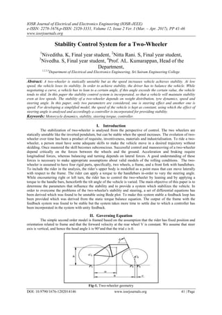
II. Governing Equation
The simple second order model is framed based on the assumption that the rider has fixed position and
orientation related to frame and that the forward velocity at the rear wheel V is constant. We assume that steer
axis is vertical, and hence the head angle λ is 90°and that the trial c is 0.
Fig-1. Two-wheeler geometry
2. Stability Control System for a Two-Wheeler
DOI: 10.9790/1676-1202014146 www.iosrjournals.org 42 | Page
Fig-2. Top view and back view of the two-wheeler
Let m be the total mass of the system,
J be the inertia of the body with respect to x-axis and
D=-Jxz which denotes the inertia product with respect to XZ axis.
The angular momentum of the system with respect to x-axis is,
𝐿 𝑥 =
𝑑𝜑
𝑑𝑡
− 𝐷𝜔 = 𝐽
𝑑𝜑
𝑑𝑡
−
𝑉
𝐷
𝛿
(1)
The torque acting on the system due to gravity and centrifugal forces and angular momentum becomes,
𝐽
𝑑2
𝜑
𝑑𝑡2
− 𝑚𝑔 𝜑 =
𝐷𝑉
𝑏
𝑑𝛿
𝑑𝑡
+
𝑚𝑉2
𝑏
𝛿
(2)
Approximately, the moment of inertia as 𝐽 = 𝑚 2
and the inertia product as = 𝑚𝑎 , the model becomes,
𝑑2
𝜑
𝑑𝑡2
−
𝑔
𝜑 =
𝑎𝑣
𝑏
𝑑𝛿
𝑑𝑡
+
𝑉2
𝑏
𝛿
(3)
Therefore,
The poles are
𝑝1,2 = ±
𝑚𝑔
𝐽
≈ ±
𝑔
(4a)
And the zeros are
𝑍 = −
𝑚𝑣
𝐷
≈ −
𝑉
𝑎
(4b)
Thus, the transfer function from steer angle δ to tilt angle Ψ is
𝐺 𝜑𝛿 𝑠 =
𝑉(𝐷𝑠 + 𝑚𝑣 )
𝑏(𝐽𝑠2 − 𝑚𝑔 )
(5)
𝐺 𝜑𝛿 𝑠 =
𝑉𝐷
𝑏𝐽
𝑠 +
𝑚𝑣
𝐷
𝑠2 −
𝑚𝑔
𝐽
≈
𝑎𝑣
𝑏
𝑠 +
𝑉
𝑎
𝑠2 −
𝑔
(6)
Here both the gain and the zero of the transfer function depends on velocity v. The above system is unstable.
Hence it is stabilised by active control using proportional feedback law.
𝛿 = −𝑘2 𝜑 (7)
Which is a closed loop system.
𝐽
𝑑2
𝜑
𝑑𝑡2
+
𝐷𝑉𝑘2
𝑏
𝑑𝜑
𝑑𝑡
+
𝑚𝑉2
𝑘2
𝑏
− 𝑚𝑔 𝜑 = 0
(8)
3. Stability Control System for a Two-Wheeler
DOI: 10.9790/1676-1202014146 www.iosrjournals.org 43 | Page
Table I. Parameters with their values that was used for the simulation
Vehicle parameters Value Unit
m 200,250 kg
b 1,1.5 m
a 0.4 m
h 0.6 m
c 0.03 m
λ 70 degree
g 9.81 m/s2
V 5,7,10 m/s
To model the front fork, we observe that the steer angle also influences the tilt angle.
The front fork roll angle is given by,
𝜑 𝑓 = 𝜑 − 𝛿 𝑐𝑜𝑠𝜆 (9)
The effective front fork angle is given by
𝛿𝑓 = 𝛿 𝑠𝑖𝑛𝜆 (10)
Let Nf and Ff be the vertical and horizontal components of the forces acting on the front wheel at the ground
contact. Neglecting dynamics and gyroscopic effect we get,
𝑁𝑓 =
𝑎𝑚𝑔
𝑏
(11)
And
𝐹𝑓 =
𝑎𝑚𝑉2
𝑏2
𝛿𝑓 =
𝑎𝑚𝑉2
𝑠𝑖𝑛𝜆
𝑏2
𝛿
(12)
Let T, be the external torque applied to the handle bar, the static torque balance of the front fork becomes,
𝑇 − 𝐹𝑓 + 𝑁𝑓 𝜑 𝑓 𝑐 sin 𝜆 = 0 (13)
𝑇 −
𝑎𝑐𝑚𝑔 sin 𝜆
𝑏
𝜑 −
𝑎𝑐𝑚 sin 𝜆
𝑏2
𝑉2
sin 𝜆 − 𝑏𝑔 cos 𝜆 𝛿 = 0
(14)
If 𝑉 > 𝑉𝑠𝑎 , then the sign of the term proportional to δ is negative.
Where,
𝑉𝑠𝑎 = 𝑏𝑔 cot 𝜆 (15)
The torque balance is written as,
𝛿 = 𝑘1 𝑣 𝑇 − 𝑘2(𝑣)𝜑 (16)
Where,
𝑘1 𝑣 =
𝑏2
𝑉2 sin 𝜆 − 𝑏𝑔 cos 𝜆 𝑚𝑎𝑐 sin 𝜆
(17)
𝑘2 𝑣 =
𝑏𝑔
𝑉2 sin 𝜆 − 𝑏𝑔 cos 𝜆
(18)
III. Simulation Results
MATLAB is the most intended software used for mathematical modelling. MATLAB is the
abbreviation of matrix laboratory. It is a multi-paradigm numerical computing environment and fourth
generation programming language. Although MATLAB indented primarily for numerical computing, an
optional toolbox allows access to symbolic computing capabilities. An additional package, Simulink, adds
graphical simulation and Model Based Design for dynamic and embedded systems.
The vehicle parameters were loaded in the MATLAB and the simulation was started. The simulation
was carried out for the open loop system. The frequency domain analysis using bode plot was done to the open
loop system. The generated results show that the open loop system is unstable.
4. Stability Control System for a Two-Wheeler
DOI: 10.9790/1676-1202014146 www.iosrjournals.org 44 | Page
Fig-3. Bode Plot of the open loop system for V=7m/s
Since the open loop system modelled was found to be unstable a closed loop was designed using the
static torque balance equation. The simulation was carried out for the closed loop system and the output plot was
generated for different magnitude of velocity.
Fig-4. Graph of the feedback system for different velocities
From the graph, it is evident that, for higher velocities the system has more oscillations and the system
takes more time to settle. The response of the system for different wheelbases was plotted for the constant
velocity V=10m/s and is depicted in the graph.
Fig-5. Graph of the feedback system for different wheelbases
The above graph, Fig-5 shows the response of the system for various wheelbases. Increase in
wheelbase of the vehicle, increases the peak overshoot of the response. The response of the system for different
masses was plotted for the constant velocity V=10m/s.
5. Stability Control System for a Two-Wheeler
DOI: 10.9790/1676-1202014146 www.iosrjournals.org 45 | Page
Fig-6. Graph of the feedback system for different mass
The above graph, Fig-6 shows the response of the system for various mass. For the vehicle with greater
mass, the peak overshoot of the system has been decreased but both the system experiences similar oscillatory
response.
IV. Proposed System
Consider a two-wheeler, negotiating a curve. The input to the vehicle is given by the rider in the form
of torque, which is applied to the handle-bar of the vehicle. The steering torque influences the steering angle
which in-turn influence the tilt angle of the system. The system can be stabilized by active steering control.
The tilt angle of the system can be sensed by the accelerometer sensor and rate gyro sensors. The
steering torque is sensed using a torque sensor and the vehicle speed is sensed using a speed sensor. Using the
outputs of the sensor, the steering angle required to vary the tilt angle is obtained. Using the calculated steering
angle, the steering torque required is calculated and it is fed to a PID controller. The PID controller stabilizes the
system as well as reduces the oscillatory response of the system. The output of the PID is given to the stepper
motor which is fitted with the handle-bar of the vehicle.
The Simulink model of the system with the PID controller was modelled and the controller was tuned
using Simulink PID tuner and it was simulated This facilitates easy comparison of the vehicle behaviour with
and without the controller.
V. Results And Discussion
The results of the closed loop system with controller has been multi-plotted with the results of closed
loop system without controller. The comparison of the system response with and without a controller has been
shown in fig-7
Fig-7. Graph of the feedback system with and without controller with a constant step change for V=10m/s
From the fig-7, it is evident that the response of the system with controller follows the desired trajectory
whereas the system without a controller oscillates and takes more time to settle.
6. Stability Control System for a Two-Wheeler
DOI: 10.9790/1676-1202014146 www.iosrjournals.org 46 | Page
Fig-8. Graph of the feedback system with and without controller with variable step change for V=10m/s
It can be thus proved by simulation that the stability system for a two-wheeler has been successfully modelled,
simulated and evaluated. The system can be implemented after modifying the front fork of the chassis.
Acknowledgement
We would like to thank for the helpful advice received from Professor Dr.S.Vaidyanathan, Department
of Mechanical Engineering and Professor Dr.K.Renganathan, Head of the Department, Department of
Electronics and Instrumentation Engineering of Sri Sairam Engineering College.
References
[1]. Mukeshkumar Prasad 1, Nilesh W. Nirwan, “Design and Fabrication of Automatic Balancing Bicycle”, International Journal of
Science, Engineering and Technology Research (IJSETR), Volume 5, Issue 2, February 2016
[2]. Ashik-E-Rasul, Nowab Md. Aminul Haq, “Stabilizing and Balancing of Linear and Rotary Inverted Pendulum System”, Bangladesh
University of Engineering and Technology (BUET) Dhaka-1000, Bangladesh February, 2016
[3]. H. Goldstein, Classical Mechanics. Addison-Wesley, Cambridge, MA, 1953. p. 145
[4]. J. Lowell and H. D. McKell. “The stability of bicycles.” Am. J. Phys. 50:12, pp. 1106–1112, 1982
[5]. M. Ghosh, S. Mukhopadhyay, “Stability Analysis of a Two-wheeler during Curve Negotiation under Braking”, 14th National
Conference on Machines and Mechanisms (NaCoMM09)
[6]. S. Timoshenko and D. H. Young, Advanced Dynamics. McGraw Hill, New York, 1948. page 239
[7]. Vipul Gupta, “Self-balancing bot”, summer project as a part electronics lab, IIT Kanpur.