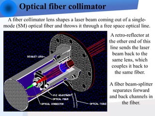
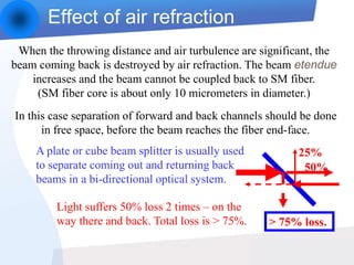
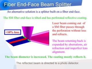
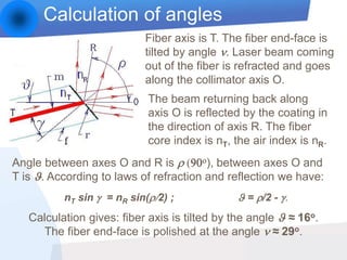
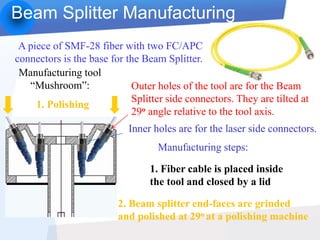
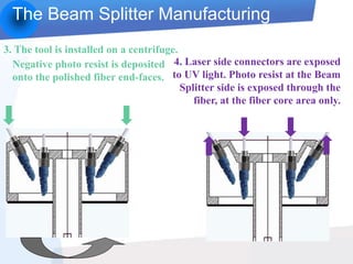
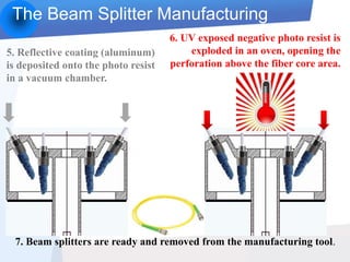
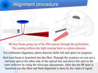
Andrei Tsiboulia
Beam-splitter at the end-face
of a single-mode fiber
Development of:
Concept Design
Manufacturing technology
Alignment procedure
Presentation goes automatically
A fiber collimator lens shapes a laser beam coming out of a single-
mode (SM) optical fiber and throws it through a free space optical line.
Optical fiber collimator
A retro-reflector at
the other end of this
line sends the laser
beam back to the
same lens, which
couples it back to
the same fiber.
A fiber beam-splitter
separates forward
and back channels in
the fiber.
When the throwing distance and air turbulence are significant, the
beam coming back is destroyed by air refraction. The beam etendue
increases and the beam cannot be coupled back to SM fiber.
(SM fiber core is about only 10 micrometers in diameter.)
In this case separation of forward and back channels should be done
in free space, before the beam reaches the fiber end-face.
A plate or cube beam splitter is usually used
to separate coming out and returning back
beams in a bi-directional optical system.
Light suffers 50% loss 2 times – on the
way there and back. Total loss is > 75%.
50%
25%
> 75% loss.
Effect of air refraction
Fiber End-Face Beam Splitter
An alternative solution is a splitter built on a fiber end-face.
The SM fiber end-face is tilted and has perforated reflective coating.
Laser beam coming out of
a SM fiber passes through
the perforation without loss
and refracts.
The beam returning back is
expanded by aberrations, air
refraction and imperfect lens
alignment.
The beam diameter is increased. The coating mostly reflects it.
<10% loss.
The reflected beam is directed to a photo detector.
Calculation of angles
Fiber axis is T. The fiber end-face is
tilted by angle n. Laser beam coming
out of the fiber is refracted and goes
along the collimator axis O.
Angle between axes O and R is r (90o), between axes O and
T is . According to laws of refraction and reflection we have:
The beam returning back along
axis O is reflected by the coating in
the direction of axis R. The fiber
core index is nT, the air index is nR.
nT sin  = nR sin(r/2) ;  = r/2 - .
Calculation gives: fiber axis is tilted by the angle  ≈ 16o.
The fiber end-face is polished at the angle n ≈ 29o.
Beam Splitter Manufacturing
A piece of SMF-28 fiber with two FC/APC
connectors is the base for the Beam Splitter.
Manufacturing tool
“Mushroom”: Outer holes of the tool are for the Beam
Splitter side connectors. They are tilted at
29o angle relative to the tool axis.
Inner holes are for the laser side connectors.
2. Beam splitter end-faces are grinded
and polished at 29o at a polishing machine
1. Polishing
1. Fiber cable is placed inside
the tool and closed by a lid
Manufacturing steps:
The Beam Splitter Manufacturing
3. The tool is installed on a centrifuge.
4. Laser side connectors are exposed
to UV light. Photo resist at the Beam
Splitter side is exposed through the
fiber, at the fiber core area only.
Negative photo resist is deposited
onto the polished fiber end-faces.
The Beam Splitter Manufacturing
5. Reflective coating (aluminum)
is deposited onto the photo resist
in a vacuum chamber.
6. UV exposed negative photo resist is
exploded in an oven, opening the
perforation above the fiber core area.
7. Beam splitters are ready and removed from the manufacturing tool.
Alignment procedure
For collimator alignment, photo detector shifts left and opens an eyepiece.
IR laser beam going out of the fiber passes through the perforation.
The coating reflects the light coming back to a photo detector.
Red laser beam is launched into the fiber. Through the eyepiece we can see a
red laser spot at the other side of the optical line and direct this spot to the
retro reflector by using the telescope adjustments. After this the IR laser is
launched into the fiber and final alignment is done by the value of signal.
Conclusion
New beam-splitter enhanced significantly
performance of a free space optical line, reduced
light loss and facilitated much the instrument
alignment because coarse alignment can be done
by using a visible radiation.
Manufacturing of the beam splitter is done by
using a modified photolithography technique.

splitter

  • 1.
    Andrei Tsiboulia Beam-splitter atthe end-face of a single-mode fiber Development of: Concept Design Manufacturing technology Alignment procedure Presentation goes automatically
  • 2.
    A fiber collimatorlens shapes a laser beam coming out of a single- mode (SM) optical fiber and throws it through a free space optical line. Optical fiber collimator A retro-reflector at the other end of this line sends the laser beam back to the same lens, which couples it back to the same fiber. A fiber beam-splitter separates forward and back channels in the fiber.
  • 3.
    When the throwingdistance and air turbulence are significant, the beam coming back is destroyed by air refraction. The beam etendue increases and the beam cannot be coupled back to SM fiber. (SM fiber core is about only 10 micrometers in diameter.) In this case separation of forward and back channels should be done in free space, before the beam reaches the fiber end-face. A plate or cube beam splitter is usually used to separate coming out and returning back beams in a bi-directional optical system. Light suffers 50% loss 2 times – on the way there and back. Total loss is > 75%. 50% 25% > 75% loss. Effect of air refraction
  • 4.
    Fiber End-Face BeamSplitter An alternative solution is a splitter built on a fiber end-face. The SM fiber end-face is tilted and has perforated reflective coating. Laser beam coming out of a SM fiber passes through the perforation without loss and refracts. The beam returning back is expanded by aberrations, air refraction and imperfect lens alignment. The beam diameter is increased. The coating mostly reflects it. <10% loss. The reflected beam is directed to a photo detector.
  • 5.
    Calculation of angles Fiberaxis is T. The fiber end-face is tilted by angle n. Laser beam coming out of the fiber is refracted and goes along the collimator axis O. Angle between axes O and R is r (90o), between axes O and T is . According to laws of refraction and reflection we have: The beam returning back along axis O is reflected by the coating in the direction of axis R. The fiber core index is nT, the air index is nR. nT sin  = nR sin(r/2) ;  = r/2 - . Calculation gives: fiber axis is tilted by the angle  ≈ 16o. The fiber end-face is polished at the angle n ≈ 29o.
  • 6.
    Beam Splitter Manufacturing Apiece of SMF-28 fiber with two FC/APC connectors is the base for the Beam Splitter. Manufacturing tool “Mushroom”: Outer holes of the tool are for the Beam Splitter side connectors. They are tilted at 29o angle relative to the tool axis. Inner holes are for the laser side connectors. 2. Beam splitter end-faces are grinded and polished at 29o at a polishing machine 1. Polishing 1. Fiber cable is placed inside the tool and closed by a lid Manufacturing steps:
  • 7.
    The Beam SplitterManufacturing 3. The tool is installed on a centrifuge. 4. Laser side connectors are exposed to UV light. Photo resist at the Beam Splitter side is exposed through the fiber, at the fiber core area only. Negative photo resist is deposited onto the polished fiber end-faces.
  • 8.
    The Beam SplitterManufacturing 5. Reflective coating (aluminum) is deposited onto the photo resist in a vacuum chamber. 6. UV exposed negative photo resist is exploded in an oven, opening the perforation above the fiber core area. 7. Beam splitters are ready and removed from the manufacturing tool.
  • 9.
    Alignment procedure For collimatoralignment, photo detector shifts left and opens an eyepiece. IR laser beam going out of the fiber passes through the perforation. The coating reflects the light coming back to a photo detector. Red laser beam is launched into the fiber. Through the eyepiece we can see a red laser spot at the other side of the optical line and direct this spot to the retro reflector by using the telescope adjustments. After this the IR laser is launched into the fiber and final alignment is done by the value of signal.
  • 10.
    Conclusion New beam-splitter enhancedsignificantly performance of a free space optical line, reduced light loss and facilitated much the instrument alignment because coarse alignment can be done by using a visible radiation. Manufacturing of the beam splitter is done by using a modified photolithography technique.