Measure laser coherence length using Michelson interferometer
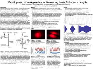
1. Figure 2. The pattern
produced with polarizer 2
removed (quantum eraser). No
fringes are apparent.
Development of an Apparatus for Measuring Laser Coherence Length
William Yang, Mentor: Dr.Michael Braunstein. Department of Physics, Central Washington University,
400 East University Way, Ellensburg, WA, 98926
Introduction
The goal of this project was to develop an apparatus to measure the
coherence length of the light waves produced by different lasers.
Coherence is a property of light that allows it to exhibit interference.
The key requirement for coherence is constant relative phase. Two
light waves that are coherent will produce a stable interference
pattern. The coherence length is the distance over which two
interacting waves maintain a constant relative phase. The method
selected to achieve the goal of the project was to introduce the laser
light into a modified Michelson interferometer arrangement while
observing and measuring the resulting interference pattern. This
pattern can be interpreted in terms of the properties of the laser light,
from which pattern was produced, including, it was predicted, its
coherence length. In order to characterize the apparatus and develop
a means of interpreting the interference patterns, two different lasers
were used: a red diode laser taken from an inexpensive laser pointer,
and a red He-Ne laser. As part of this project the quantum eraser
phenomenon and bandwidth of the diode and He-Ne lasers were also
investigated. The project is continuing an investigation of the utility of
the apparatus for coherence length measurements.
Method
• The Michelson interferometer we used consists of a beam splitter
which sends portions of the incident beam to two mirrors on different
perpendicular arms; the portion in each arm has a different
polarization
• Upon reflection at the mirrors, the two beams are recombined at the
beam splitter producing an interference pattern; the total effect of the
quarter-wave plates in each arm is to rotate the polarization by 90
so that the beam splitter will direct the light from each arm to the
output port
• Polarizer 1 provided a means to balance the intensity of polarized
light in each arm
• The adjustable mirror was on a stage that could be translated
(scanned) with a micrometer
• For data collection the interference signal produced by the
interferometer was detected with either a CCD camera or a
photodiode with signal displayed on an oscilloscope
• Model calculations were performed using Mathematica
Conclusion
• The He-Ne laser had a smaller bandwidth than the diode
laser. This result is consistent with the model we built.
• For large changes of the position of the adjustable mirror, we
observed that the maximum of the fringe visibility decreased
for the diode laser. We believe that this is associated with
coherence length of the diode laser.
• It should be possible to obtain data quantifying the
coherence length of the diode laser.
Reference
http://www.worldoflasers.com/laserproperties.htm
http://www.rp-photonics.com/bandwidth.html
http://www.scientificamerican.com/article.cfm?id=a-do-it-yourself-
quantum-eraser
Hecht, E. (1990). Optics (2nd ed.): Addison-Wesley.
Figure 3. The pattern
produced with polarizer 2
inserted. Obvious interference
fringes are produced,
demonstrating the quantum
eraser effect.
Figure 4. Fringes produced by
the He-Ne laser by scanning the
adjustable mirror. The data
shown in red was obtained at a
location that was a maximum of
visibility for fringes for the diode
laser and that shown in blue is
at a location of minimum visibility
for the diode laser fringes. For
the He-Ne laser, visibility is
nearly constant.
Figure 5. Fringes produced by
the Diode laser by scanning the
adjustable mirror. The data
shown in red was obtained at a
location that was a maximum of
visibility for fringes, and the blue
is half way between a location
of maximum and minimum
visibility. The change in visibility
is due to the laser bandwidth.
Results
• Demonstrated the interference pattern produced by the
Michelson interferometer for both lasers
• Demonstrated that the visibility of the interference pattern
changes as the position of the adjustable mirror changes
• Demonstrated the quantum eraser phenomenon
• Demonstrated the contrast in bandwidth between the diode laser
and the He-Ne laser
Figure 1. Schematic of the apparatus of the modified Michelson
interferometer used in this project. ---Red arrows indicate the direction
of the reflected beams . ---Blue arrows indicate the direction of the
recombined beam at output port at the beam splitter. The polarizing
beam splitter used in this apparatus sends different polarizations into
the two arms. Each polarizer allows only a specific linear polarization
to pass. The λ/4 waveplates alter the polarization of light as it passes
through. The spatial filter and iris “cleaned up” the incident beam to
provide a smooth intensity profile. The converging lens was placed
with its focus point at the pin hole of the spatial filter, so it converted a
diverging beam into a parallel beam.
Figure 6. The top graph illustrates a model calculation for fringes
produced by small changes in the position of the adjustable
mirror. The two graphs on the bottom illustrate model calculations
for larger changes in the position of the adjustable mirror: on the
left, a source with a wide bandwidth, and on the right, a source
with a narrow bandwidth.
-0.01
-0.005
0
0.005
0.01
0.015
0.02
0.025
0.03
0.035
0.04
-0.06 -0.04 -0.02 0 0.02 0.04 0.06
PhotodiodeDetector
Output(V)
Time (s)
-0.03
-0.02
-0.01
0
0.01
0.02
0.03
0.04
0.05
0.06
0.07
0.08
-0.15 -0.1 -0.05 0 0.05 0.1 0.15
PhotodiodeDetector
Output(V)
Time(s)
Data
Acknowledgments
This project was made possible in part by equipment provided
by the CWU Chapter of the Society of Physics Students;
equipment and supplies provided by the CWU Physics
Department