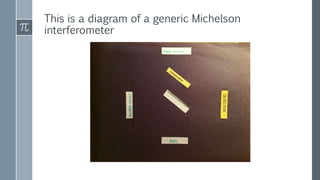
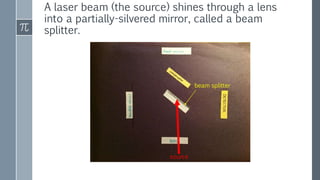
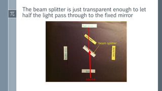
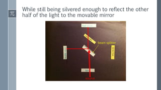
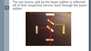
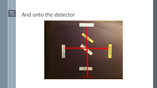
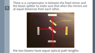
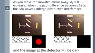
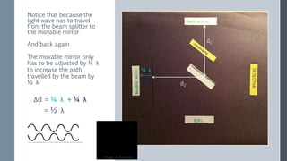
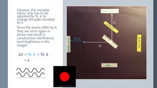
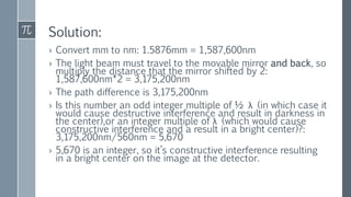
A Visual Explanation of
the Michelson
Interferometer
Tara L.
This is a diagram of a generic Michelson
interferometer
A laser beam (the source) shines through a lens
into a partially-silvered mirror, called a beam
splitter.
beam splitter
source
The beam splitter is just transparent enough to let
half the light pass through to the fixed mirror
beam splitter
source
While still being silvered enough to reflect the other
half of the light to the movable mirror
beam splitter
source
The two beams split by the beam splitter is reflected
off of their respective mirrors, back through the beam
splitter
beam splitter
source
And onto the detector
source
There is a compensator in between the fixed mirror and
the beam splitter to make sure that when the mirrors are
at equal distances from each other,
source
the two beams have equal optical path lengths.
compensator
Initially, the two mirrors are at equal distances from
the beam splitter (d1=d2). There is no difference in
path length, the light waves are in phase,
source
and the detector shows an image that is bright in the
center
d1
d2
Image at detector
http://www.lightandmatter.com/html_books/0sn/ch06/figs/hw-sine-wave.png
As you move the movable mirror away, d2 will
increase. When the path difference becomes ½ λ,
the two waves undergo destructive interference,
and the image at the detector will be dark
d1
d1
d2 d2
Image at detectorImage at detector
http://www.lightandmatter.com/html_books/0sn/ch06/figs/hw-sine-wave.png http://www.lightandmatter.com/html_books/0sn/ch06/figs/hw-sine-wave.png
Notice that because the
light wave has to travel
from the beam splitter to
the movable mirror
And back again
The movable mirror only
has to be adjusted by ¼ λ
to increase the path
travelled by the beam by
½ λ d2
d1
¼ λ
¼ λ
Δd = ¼ λ + ¼ λ
= ½ λ
Image at detector
http://www.lightandmatter.com/html_books/0sn/ch06/figs/hw-sine-wave.png
Since the waves differ by λ,
they are once again in
phase and result in
constructive interference
(and brightness in the
image). d2
d1
½ λ
½ λ
Δd = ½ λ + ½ λ
= λ
Image at detector
http://www.lightandmatter.com/html_books/0sn/ch06/figs/hw-sine-wave.png
Likewise, the movable
mirror only has to be
adjusted by ½ λ to
change the path travelled
by λ.
Here’s a quick question to make sure you’re
getting this:
› Assume your laser has a wavelength of 560nm, and your
mirrors start at equal distances from the beam splitter
› You shift your movable mirror by 1.5876mm
› What’s the path difference between your two mirrors
now?
› Is the center of the image on your detector dark, or
bright?
Solution:
› Convert mm to nm: 1.5876mm = 1,587,600nm
› The light beam must travel to the movable mirror and back, so
multiply the distance that the mirror shifted by 2:
1,587,600nm*2 = 3,175,200nm
› The path difference is 3,175,200nm
› Is this number an odd integer multiple of ½ λ (in which case it
would cause destructive interference and result in darkness in
the center),or an integer multiple of λ (which would cause
constructive interference and a result in a bright center)?:
3,175,200nm/560nm = 5,670
› 5,670 is an integer, so it’s constructive interference resulting
in a bright center on the image at the detector.

A visual explanation of the Michelson Interferometer

  • 1.
    A Visual Explanationof the Michelson Interferometer Tara L.
  • 2.
    This is adiagram of a generic Michelson interferometer
  • 3.
    A laser beam(the source) shines through a lens into a partially-silvered mirror, called a beam splitter. beam splitter source
  • 4.
    The beam splitteris just transparent enough to let half the light pass through to the fixed mirror beam splitter source
  • 5.
    While still beingsilvered enough to reflect the other half of the light to the movable mirror beam splitter source
  • 6.
    The two beamssplit by the beam splitter is reflected off of their respective mirrors, back through the beam splitter beam splitter source
  • 7.
    And onto thedetector source
  • 8.
    There is acompensator in between the fixed mirror and the beam splitter to make sure that when the mirrors are at equal distances from each other, source the two beams have equal optical path lengths. compensator
  • 9.
    Initially, the twomirrors are at equal distances from the beam splitter (d1=d2). There is no difference in path length, the light waves are in phase, source and the detector shows an image that is bright in the center d1 d2 Image at detector http://www.lightandmatter.com/html_books/0sn/ch06/figs/hw-sine-wave.png
  • 10.
    As you movethe movable mirror away, d2 will increase. When the path difference becomes ½ λ, the two waves undergo destructive interference, and the image at the detector will be dark d1 d1 d2 d2 Image at detectorImage at detector http://www.lightandmatter.com/html_books/0sn/ch06/figs/hw-sine-wave.png http://www.lightandmatter.com/html_books/0sn/ch06/figs/hw-sine-wave.png
  • 11.
    Notice that becausethe light wave has to travel from the beam splitter to the movable mirror And back again The movable mirror only has to be adjusted by ¼ λ to increase the path travelled by the beam by ½ λ d2 d1 ¼ λ ¼ λ Δd = ¼ λ + ¼ λ = ½ λ Image at detector http://www.lightandmatter.com/html_books/0sn/ch06/figs/hw-sine-wave.png
  • 12.
    Since the wavesdiffer by λ, they are once again in phase and result in constructive interference (and brightness in the image). d2 d1 ½ λ ½ λ Δd = ½ λ + ½ λ = λ Image at detector http://www.lightandmatter.com/html_books/0sn/ch06/figs/hw-sine-wave.png Likewise, the movable mirror only has to be adjusted by ½ λ to change the path travelled by λ.
  • 13.
    Here’s a quickquestion to make sure you’re getting this: › Assume your laser has a wavelength of 560nm, and your mirrors start at equal distances from the beam splitter › You shift your movable mirror by 1.5876mm › What’s the path difference between your two mirrors now? › Is the center of the image on your detector dark, or bright?
  • 14.
    Solution: › Convert mmto nm: 1.5876mm = 1,587,600nm › The light beam must travel to the movable mirror and back, so multiply the distance that the mirror shifted by 2: 1,587,600nm*2 = 3,175,200nm › The path difference is 3,175,200nm › Is this number an odd integer multiple of ½ λ (in which case it would cause destructive interference and result in darkness in the center),or an integer multiple of λ (which would cause constructive interference and a result in a bright center)?: 3,175,200nm/560nm = 5,670 › 5,670 is an integer, so it’s constructive interference resulting in a bright center on the image at the detector.