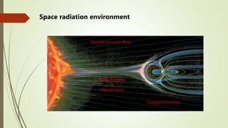
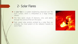
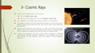
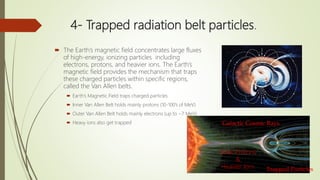
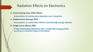
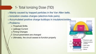
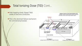
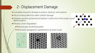
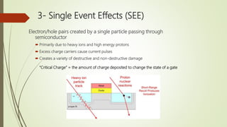
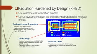
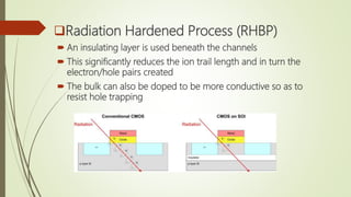
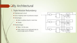
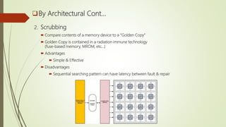
Space radiation effects on
electronics and mitigation
methods
Presented by:
Eng. Ahmed Samir Koriem
Presentation outlines
Space radiation environment
Radiation effects on electronics
Mitigation methods
Latest new approaches using FPGA
Galactic Cosmic Rays
Solar Protons
&
Heavier Ions
Trapped Particles
Space radiation environment
1- The Solar Wind
 Because of the high temperature of the Sun's corona,
solar protons and electrons acquire velocities in excess of
the escape velocity from the sun. The result is that there is
a continuous outward flow of charged particles in all
directions from the sun. This flow of particles is called the
solar wind
 The velocity and density of the solar wind vary with
sunspot activity.
 The solar wind causes a radiation pressure on satellites in
orbit around the Earth
2- Solar Flares
 A solar flare is a sudden brightening observed over the
Sun's surface, which is interpreted as a large energy
release
 The flare ejects clouds of electrons, ions, and atoms
through the corona of the sun into space.
 High speed solar protons emitted by a solar flare are
probably the most potent of the radiation hazards to
space flight.
3- Cosmic Rays
 Cosmic rays originate from two sources:
 The Sun (solar cosmic rays),
 Other stars throughout the universe (galactic cosmic rays).
 This radiation is primarily high velocity protons and electrons.
 The galactic cosmic rays are extremely energetic, but do not pose a
serious threat, due to the low flux, the rate at which they enter the
atmosphere.
 Cosmic rays have the most impact on polar and geosynchronous
orbits. This is due to the fact that they are outside or near the edge
of the protective shielding provided by Earth's magnetic field
 Cosmic ray particles can also cause direct damage to internal
components through collision. Shielding is not feasible due to the
high energy of the particles and the weight of the shielding
required.
4- Trapped radiation belt particles.
 The Earth’s magnetic field concentrates large fluxes
of high-energy, ionizing particles including
electrons, protons, and heavier ions. The Earth’s
magnetic field provides the mechanism that traps
these charged particles within specific regions,
called the Van Allen belts.
 Earth’s Magnetic Field traps charged particles
 Inner Van Allen Belt holds mainly protons (10-100’s of MeV)
 Outer Van Allen Belt holds mainly electrons (up to ~7 MeV)
 Heavy ions also get trapped Galactic Cosmic Rays
Solar Protons
&
Heavier Ions Trapped Particles
Radiation Effects on Electronics
 Total ionizing dose (TID) effects
Accumulation of ionizing dose deposition over a long time.
 Displacement damage (DD)
Accumulation of crystal lattice defects caused by high energy radiation.
 Single event effects (SEE)
A high ionizing dose deposition, from a single high energy particle,
occurring in a sensitive region of the device.
1- Total Ionizing Dose (TID)
o Mainly caused by trapped particles in the Van Allen belts.
o Ionization creates charges (electron-hole pairs).
oAccumulated positive charge buildups in insulators/oxides.
o Problems:
» Threshold Shifts
» Leakage Current
» Timing Changes
» Circuit parameters are changed
» Ultimately, the circuit ceases to function properly
Hole trapping slowly “dopes” field
oxides to become conductive
This is the dominant failure mechanism
for commercial processes
Total Ionizing Dose (TID) Cont…
2- Displacement Damage
Cumulative long term damage to protons, electrons, and neutrons
Not an ionizing effect but rather collision damage
Energetic particles (protons/ions) displace Si-atoms from their proper crystal
lattice locations.
Minority Carrier Degradation
Reduced gain & switching speed
Particularly damaging for optoelectronic & linear circuits
3- Single Event Effects (SEE)
Electron/hole pairs created by a single particle passing through
semiconductor
 Primarily due to heavy ions and high energy protons
 Excess charge carriers cause current pulses
 Creates a variety of destructive and non-destructive damage
“Critical Charge” = the amount of charge deposited to change the state of a gate
Single Event Effects (SEE) - Non-Destructive (e.g., soft
faults)
Single Event Transients (SET)
- An induced pulse that can flip a gate
- Temporary glitches in combinational logic
Single Event Upsets (SEU)
- The pulse is captured by a storage device resulting
in a state change
Single Event Effects (SEE) - – Destructive (e.g., hard faults)
Single Event Latchup (SEL)
- Parasitic NPN/PNP transistors are put
into positive feedback condition (PNPN).
- Runaway current damages device
- Due to heavy ions, protons, neutrons.
Single Event Burnout (SEB)
- Localized current in body of device turns
on parasitic bipolar transistors.
- Runaway current causes heat.
- Due primarily to heavy ions.
Clementine
 Launched on January 25 1994, in order to qualify component
technologies and make scientific observations of the Moon and a
near-Earth asteroid.
 On May 7 1994 its main on-board computer sent out an
unintentional command that caused one of the attitude-control
thruster to fire, before the computer crashed. By the time the ground
control had rebooted the computer the attitude control fuel tanks
were empty, and the spacecraft was spinning very fast.
 This made it impossible to continue the mission.
 This failure was probably caused by a SEU.
 A single bit flip could have no consequences at all or, if unlucky with
when and where it happens, could completely destroy a spacecraft.
Mitigation Techniques
By Shielding
Shielding helps for protons and electrons <30MeV
Shielding to lower the radiation dose level (using e.g. Al,
Cu)
 Unable to deal with high-energy particles.
Radiation Hardened by Design (RHBD)
 Uses commercial fabrication process
 Circuit layout techniques are implemented which help mitigate
effects
Enclosed Layout Transistors
- Eliminates edge of drain terminal
- This eliminates any leakage current
between source & drain due near edge
of gate (STI Region 1)
Guard Rings
- Reduces leakage between NMOS & PMOS
devices due to hole trapping in Field Oxide
(STI Region 2)
- Separation of device + body contacts
- Adds ~20% increase in area
Thin Gate Oxide
- This oxide reduces probability of hold trapping.
- Process nodes <0.5um typically are immune to Vgs
shift in the gate.
Radiation Hardened Process (RHBP)
 An insulating layer is used beneath the channels
 This significantly reduces the ion trail length and in turn the
electron/hole pairs created
 The bulk can also be doped to be more conductive so as to
resist hole trapping
By Architectural
1. Triple Module Redundancy
 Triplicate each circuit
 Use a majority voter to produces output
 Advantages
 Able to address faults in real-time
 Simple
 Disadvantages
 Takes >3x the area
 Voter needs to be triplicated also to
avoid single-point-of-failure
By Architectural Cont…
2. Scrubbing
 Compare contents of a memory device to a “Golden Copy”
 Golden Copy is contained in a radiation immune technology
(fuse-based memory, MROM, etc…)
 Advantages
 Simple & Effective
 Disadvantages
 Sequential searching pattern can have latency between fault & repair
By Architectural Cont…
3. Error Correction Codes
 A variety of error detection & correction codes exist (CRC, Hamming, Parity…)
 CRCs can be included as part of memory system
 Advantages
 Quick Handling of Errors
 Disadvantages
 Faults in a configuration memory can alter circuitry momentarily before error codes
performs correction
Latest new approaches using FPGA
 FPGAs are Uniquely Susceptible
1. Total Ionizing Dose
 All gates and memory cells are susceptible to TID due to high energy protons
2. Single Event Effects
 SETs/SEUs in the logic blocks
 SETs in the routing
23
Radiation Strikes
in the
Circuit Fabric
(Logic + Routing)
Radiation Strikes
in the
Configuration Memory
(Logic + Routing)
What is needed for FPGA-Based Reconfigurable Computing
1. SRAM-based FPGAs
 To support fast reconfiguration
2. A TID hardened fabric
 Thin Gate Oxides to avoid hole trapping and threshold shifting (inherent in all processes)
 Radiation Hardened by Design to provide SEL immunity (rings, layout, etc…
Does This Exist?
 Yes, Xilinx Virtex-QV Space Grade FPGA Family
 TID Immunity > 1Mrad
 RHBD for SEL immunity
 CRC
The Final Piece is SEE Fault Mitigation due to Heavy Ions
 SEU will happen due to heavy ions, nothing can stop this.
 A computer architecture that expects and response to faults is needed.
Fault Tolerance approaches:
1. TMR + Spares
2. Spatial Avoidance of Background Repair
3. Scrubbing
25
1. TMR + Spares
 3 Tiles run in TMR with the rest reserved as spares.
 In the event of a fault, the damaged tile is replaced
with a spare and foreground operation continues.
2. Spatial Avoidance & Repair
 The damaged Tile is “repaired” in the background via
Partial Reconfiguration.
 The repaired tile is reintroduced into the system as an
available spare.
 3. Scrubbing
 A traditional scrubber runs in the background.
 Either blind or read-back.
 PR is technically a “blind scrub”, but of a particular
region of the FPGA.
Shuttle Flight
Computer
(TMR + Spare)
CONCLUSION
 Radiation is a process in which energetic particles or energy or
waves travel through a medium or space
Radiation hardening is a method of designing and testing
electronic components and systems to make them resistant to
damage or malfunctions caused by ionizing radiation
 Radiation hardening requires electronic chip manufacturers to
create both Physical and logical shields to protect the hardware
Radiation hardened chips are made by two methods: -
• Radiation hardening by process (RHBP)
• Radiation hardening by design (RHBD).

Space radiation effects on electronics and mitigation methods

  • 1.
    Space radiation effectson electronics and mitigation methods Presented by: Eng. Ahmed Samir Koriem
  • 2.
    Presentation outlines Space radiationenvironment Radiation effects on electronics Mitigation methods Latest new approaches using FPGA
  • 3.
    Galactic Cosmic Rays SolarProtons & Heavier Ions Trapped Particles Space radiation environment
  • 4.
    1- The SolarWind  Because of the high temperature of the Sun's corona, solar protons and electrons acquire velocities in excess of the escape velocity from the sun. The result is that there is a continuous outward flow of charged particles in all directions from the sun. This flow of particles is called the solar wind  The velocity and density of the solar wind vary with sunspot activity.  The solar wind causes a radiation pressure on satellites in orbit around the Earth
  • 5.
    2- Solar Flares A solar flare is a sudden brightening observed over the Sun's surface, which is interpreted as a large energy release  The flare ejects clouds of electrons, ions, and atoms through the corona of the sun into space.  High speed solar protons emitted by a solar flare are probably the most potent of the radiation hazards to space flight.
  • 6.
    3- Cosmic Rays Cosmic rays originate from two sources:  The Sun (solar cosmic rays),  Other stars throughout the universe (galactic cosmic rays).  This radiation is primarily high velocity protons and electrons.  The galactic cosmic rays are extremely energetic, but do not pose a serious threat, due to the low flux, the rate at which they enter the atmosphere.  Cosmic rays have the most impact on polar and geosynchronous orbits. This is due to the fact that they are outside or near the edge of the protective shielding provided by Earth's magnetic field  Cosmic ray particles can also cause direct damage to internal components through collision. Shielding is not feasible due to the high energy of the particles and the weight of the shielding required.
  • 7.
    4- Trapped radiationbelt particles.  The Earth’s magnetic field concentrates large fluxes of high-energy, ionizing particles including electrons, protons, and heavier ions. The Earth’s magnetic field provides the mechanism that traps these charged particles within specific regions, called the Van Allen belts.  Earth’s Magnetic Field traps charged particles  Inner Van Allen Belt holds mainly protons (10-100’s of MeV)  Outer Van Allen Belt holds mainly electrons (up to ~7 MeV)  Heavy ions also get trapped Galactic Cosmic Rays Solar Protons & Heavier Ions Trapped Particles
  • 9.
    Radiation Effects onElectronics  Total ionizing dose (TID) effects Accumulation of ionizing dose deposition over a long time.  Displacement damage (DD) Accumulation of crystal lattice defects caused by high energy radiation.  Single event effects (SEE) A high ionizing dose deposition, from a single high energy particle, occurring in a sensitive region of the device.
  • 10.
    1- Total IonizingDose (TID) o Mainly caused by trapped particles in the Van Allen belts. o Ionization creates charges (electron-hole pairs). oAccumulated positive charge buildups in insulators/oxides. o Problems: » Threshold Shifts » Leakage Current » Timing Changes » Circuit parameters are changed » Ultimately, the circuit ceases to function properly
  • 11.
    Hole trapping slowly“dopes” field oxides to become conductive This is the dominant failure mechanism for commercial processes Total Ionizing Dose (TID) Cont…
  • 12.
    2- Displacement Damage Cumulativelong term damage to protons, electrons, and neutrons Not an ionizing effect but rather collision damage Energetic particles (protons/ions) displace Si-atoms from their proper crystal lattice locations. Minority Carrier Degradation Reduced gain & switching speed Particularly damaging for optoelectronic & linear circuits
  • 13.
    3- Single EventEffects (SEE) Electron/hole pairs created by a single particle passing through semiconductor  Primarily due to heavy ions and high energy protons  Excess charge carriers cause current pulses  Creates a variety of destructive and non-destructive damage “Critical Charge” = the amount of charge deposited to change the state of a gate
  • 14.
    Single Event Effects(SEE) - Non-Destructive (e.g., soft faults) Single Event Transients (SET) - An induced pulse that can flip a gate - Temporary glitches in combinational logic Single Event Upsets (SEU) - The pulse is captured by a storage device resulting in a state change
  • 15.
    Single Event Effects(SEE) - – Destructive (e.g., hard faults) Single Event Latchup (SEL) - Parasitic NPN/PNP transistors are put into positive feedback condition (PNPN). - Runaway current damages device - Due to heavy ions, protons, neutrons. Single Event Burnout (SEB) - Localized current in body of device turns on parasitic bipolar transistors. - Runaway current causes heat. - Due primarily to heavy ions.
  • 16.
    Clementine  Launched onJanuary 25 1994, in order to qualify component technologies and make scientific observations of the Moon and a near-Earth asteroid.  On May 7 1994 its main on-board computer sent out an unintentional command that caused one of the attitude-control thruster to fire, before the computer crashed. By the time the ground control had rebooted the computer the attitude control fuel tanks were empty, and the spacecraft was spinning very fast.  This made it impossible to continue the mission.  This failure was probably caused by a SEU.  A single bit flip could have no consequences at all or, if unlucky with when and where it happens, could completely destroy a spacecraft.
  • 17.
    Mitigation Techniques By Shielding Shieldinghelps for protons and electrons <30MeV Shielding to lower the radiation dose level (using e.g. Al, Cu)  Unable to deal with high-energy particles.
  • 18.
    Radiation Hardened byDesign (RHBD)  Uses commercial fabrication process  Circuit layout techniques are implemented which help mitigate effects Enclosed Layout Transistors - Eliminates edge of drain terminal - This eliminates any leakage current between source & drain due near edge of gate (STI Region 1) Guard Rings - Reduces leakage between NMOS & PMOS devices due to hole trapping in Field Oxide (STI Region 2) - Separation of device + body contacts - Adds ~20% increase in area Thin Gate Oxide - This oxide reduces probability of hold trapping. - Process nodes <0.5um typically are immune to Vgs shift in the gate.
  • 19.
    Radiation Hardened Process(RHBP)  An insulating layer is used beneath the channels  This significantly reduces the ion trail length and in turn the electron/hole pairs created  The bulk can also be doped to be more conductive so as to resist hole trapping
  • 20.
    By Architectural 1. TripleModule Redundancy  Triplicate each circuit  Use a majority voter to produces output  Advantages  Able to address faults in real-time  Simple  Disadvantages  Takes >3x the area  Voter needs to be triplicated also to avoid single-point-of-failure
  • 21.
    By Architectural Cont… 2.Scrubbing  Compare contents of a memory device to a “Golden Copy”  Golden Copy is contained in a radiation immune technology (fuse-based memory, MROM, etc…)  Advantages  Simple & Effective  Disadvantages  Sequential searching pattern can have latency between fault & repair
  • 22.
    By Architectural Cont… 3.Error Correction Codes  A variety of error detection & correction codes exist (CRC, Hamming, Parity…)  CRCs can be included as part of memory system  Advantages  Quick Handling of Errors  Disadvantages  Faults in a configuration memory can alter circuitry momentarily before error codes performs correction
  • 23.
    Latest new approachesusing FPGA  FPGAs are Uniquely Susceptible 1. Total Ionizing Dose  All gates and memory cells are susceptible to TID due to high energy protons 2. Single Event Effects  SETs/SEUs in the logic blocks  SETs in the routing 23 Radiation Strikes in the Circuit Fabric (Logic + Routing) Radiation Strikes in the Configuration Memory (Logic + Routing)
  • 24.
    What is neededfor FPGA-Based Reconfigurable Computing 1. SRAM-based FPGAs  To support fast reconfiguration 2. A TID hardened fabric  Thin Gate Oxides to avoid hole trapping and threshold shifting (inherent in all processes)  Radiation Hardened by Design to provide SEL immunity (rings, layout, etc… Does This Exist?  Yes, Xilinx Virtex-QV Space Grade FPGA Family  TID Immunity > 1Mrad  RHBD for SEL immunity  CRC The Final Piece is SEE Fault Mitigation due to Heavy Ions  SEU will happen due to heavy ions, nothing can stop this.  A computer architecture that expects and response to faults is needed.
  • 25.
    Fault Tolerance approaches: 1.TMR + Spares 2. Spatial Avoidance of Background Repair 3. Scrubbing 25 1. TMR + Spares  3 Tiles run in TMR with the rest reserved as spares.  In the event of a fault, the damaged tile is replaced with a spare and foreground operation continues. 2. Spatial Avoidance & Repair  The damaged Tile is “repaired” in the background via Partial Reconfiguration.  The repaired tile is reintroduced into the system as an available spare.  3. Scrubbing  A traditional scrubber runs in the background.  Either blind or read-back.  PR is technically a “blind scrub”, but of a particular region of the FPGA. Shuttle Flight Computer (TMR + Spare)
  • 26.
    CONCLUSION  Radiation isa process in which energetic particles or energy or waves travel through a medium or space Radiation hardening is a method of designing and testing electronic components and systems to make them resistant to damage or malfunctions caused by ionizing radiation  Radiation hardening requires electronic chip manufacturers to create both Physical and logical shields to protect the hardware Radiation hardened chips are made by two methods: - • Radiation hardening by process (RHBP) • Radiation hardening by design (RHBD).