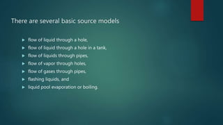
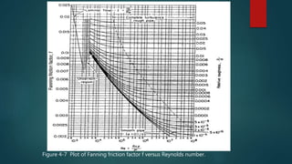
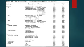
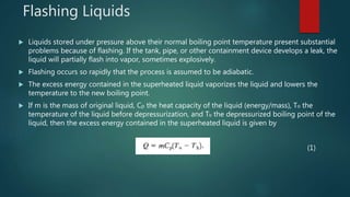
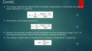
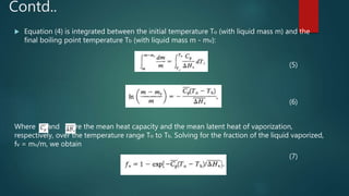
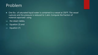
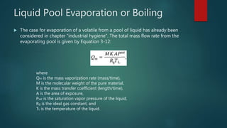
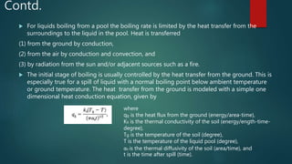
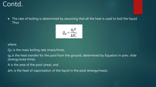
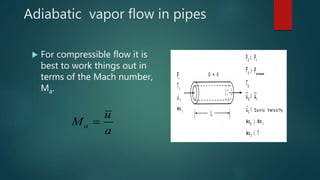
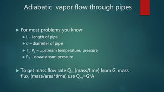
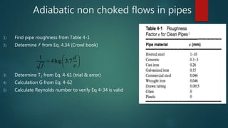
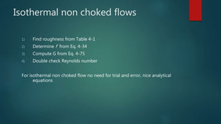
Source Models
 Accidents begin with an incident, which usually results in the loss of containment of material
from the process.
 The material has hazardous properties, which might include toxic properties and energy
content.
 Typical incidents might include the rupture or break of a pipeline, a hole in a tank or pipe,
runaway reaction, or fire external to the vessel.
 Once the incident is known, source models are selected to describe how materials are
discharged from the process.
 The source model provides a description of the rate of discharge, the total quantity discharged
(or total time of discharge), and the state of the discharge (that is, solid, liquid, vapor, or a
combination).
 Source models are constructed from fundamental or empirical equations representing the
physicochemical processes occurring during the release of materials.
There are several basic source models
 flow of liquid through a hole,
 flow of liquid through a hole in a tank,
 flow of liquids through pipes,
 flow of vapor through holes,
 flow of gases through pipes,
 flashing liquids, and
 liquid pool evaporation or boiling.
Flow of Liquids through Pipes
 Flow of incompressible liquids through pipes is described by the mechanical energy balance. The net result is
(1)
where
 P is the pressure (force/area),
 p is the fluid density (mass/volume),
 u is the average instantaneous velocity of the fluid (length/time),
 gc is the gravitational constant (length mass/force time2),
 α is the unit less velocity profile correction factor with the following values:
 α = 0.5 for laminar flow, α = 1.0 for plug flow, and α =1.0 for turbulent flow,
 g is the acceleration due to gravity (length/time2),
 z is the height above datum (length),
 F is the net frictional loss term (length force/mass),
 Ws is the shaft work (force length), and
 m is the mass flow rate (mass/time).
Contd..
 The frictional loss term F in Equation (1) represents the loss of mechanical energy resulting from friction
and includes losses resulting from flow through lengths of pipe; fittings such as valves, elbows, orifices;
and pipe entrances and exits.
 For each frictional device a loss term of the following form is used:
(2)
where
Kf is the excess head loss due to the pipe or pipe fitting (dimensionless) and
u is the fluid velocity (length/time).
 For fluids flowing through pipes the excess head loss term Kf is given by
(3)
f is the Fanning friction factor (unit less),
L is the flow path length (length), and
d is the flow path diameter (length).
Contd..
 The Fanning friction factor f is a function of the Reynolds
number Re and the roughness of the pipe ε.
 For laminar flow the Fanning friction factor is given by
(4)
 For turbulent flow the data shown in Figure 4-7 are
represented by the Colebrook equation:
(5)
An alternative form of Equation (5), useful for determining the
Reynolds number from the friction factor f, is
(6)
Figure 4-7 Plot of Fanning friction factor f versus Reynolds number.
Contd..
 For fully developed turbulent flow in rough pipes, f is independent of the Reynolds number, as
shown by the nearly constant friction factors at high Reynolds number in Figure 4-7. For this
case Equation (6) is simplified to
(7)
 For smooth pipes, ε = 0 and Equation (5) reduces to
(8)
 For smooth pipe with a Reynolds number less than 100,000 the following Blasius
approximation to Equation (8) is useful:
(9)
Contd..
 A single equation has been proposed by Chen to provide the friction factor f
over the entire range of Reynolds numbers shown in Figure 4-7. This equation
is
(10)
where
2-K Method
 For pipe fittings, valves, and other flow obstructions the traditional method has been to use an
equivalent pipe length Lequiv in Equation (3).
 An improved approach is to use the 2-K method, which uses the actual flow path length in Equation
(3)
 equivalent lengths are not used and provides a more detailed approach for pipe fittings, inlets, and
outlets.
 The 2-K method defines the excess head loss in terms of two constants, the Reynolds number and
the pipe internal diameter:
(11)
where
 Kf is the excess head loss (dimensionless),
 K1 and K∞ are constants (dimensionless),
 Re is the Reynolds number (dimensionless), and
 IDinches is the internal diameter of the flow path (inches).
Contd..
 For pipe entrances and exits Equation 4-38 is modified to account for the change in kinetic
energy:
(12)
 For pipe entrances, K1 = 160 and K∞ = 0.50 for a normal entrance
 For pipe exits, K1 = 0 and K∞ = 1.0
 The K factors for the entrance and exit effects account for the changes in kinetic energy
through these piping changes, so no additional kinetic energy terms in the mechanical
energy balance must be considered.
 For high Reynolds numbers (that is, Re > 10,000) the first term in Equation (12) is negligible
and
 For low Reynolds numbers (that is, Re < 50) the first term dominates and
The solution procedure to determine the mass flow rate of discharged material from a
piping system is as follows:
1. Given: the length, diameter, and type of pipe; pressures and elevation changes across
the piping system; work input or output to the fluid resulting from pumps, turbines, etc.;
number and type of fittings in the pipe; properties of the fluid, including density and
viscosity.
2. Specify the initial point (point 1) and the final point (point 2). This must be done
carefully because the individual terms in Equation (1) are highly dependent on this
specification.
3. Determine the pressures and elevations at points 1 and 2. Determine the initial fluid
velocity at point 1.
4. Guess a value for the velocity at point 2.
5. Determine the friction factor for the pipe using Equations (4 ) through (10).
The solution procedure to determine the mass flow rate of discharged material from a
piping system is as follows:
6. Determine the excess head loss terms for the pipe (using Equation 3), for the fittings
(using Equation 11), and for any entrance and exit effects (using Equation 12). Sum the
head loss terms, and compute the net frictional loss term using Equation (2). Use the
velocity at point 2.
7. Compute values for all the terms in Equation (1), and substitute into the equation. If
the sum of all the terms in Equation (1) is zero, then the computation is completed. If
not, go back to step 4 and repeat the calculation.
8. Determine the mass flow rate using the equation m = ρuA.
If fully developed turbulent flow is expected, the solution is direct. Substitute the
known terms into Equation (1), leaving the velocity at point 2 as a variable. Solve
for the velocity directly.
Problem 1
 Water contaminated with small amounts of hazardous waste is gravity-drained out of a
large storage tank through a straight commercial steel pipe, 100 mm ID (internal
diameter). The pipe is 100 m long with a gate valve near the tank. The entire pipe
assembly is mostly horizontal. If the liquid level in the tank is 5.8 m above the pipe
outlet, and the pipe is accidently severed 33 m from the tank, compute the flow rate of
material escaping from the pipe.
Problem 2
 Compute the pressure in the pipe at the location shown on Figure 4-17. The flow rate
through the pipe is 10,000 L/hr. The pipe is commercial steel pipe with an internal
diameter of 50 mm. The liquid in the pipe is crude oil with a density of 928 kg/m3 and
a viscosity of 0.004 kg/m s. The tank is vented to the atmosphere.
Flashing Liquids
 Liquids stored under pressure above their normal boiling point temperature present substantial
problems because of flashing. If the tank, pipe, or other containment device develops a leak, the
liquid will partially flash into vapor, sometimes explosively.
 Flashing occurs so rapidly that the process is assumed to be adiabatic.
 The excess energy contained in the superheated liquid vaporizes the liquid and lowers the
temperature to the new boiling point.
 If m is the mass of original liquid, Cp the heat capacity of the liquid (energy/mass), To the
temperature of the liquid before depressurization, and Tb the depressurized boiling point of the
liquid, then the excess energy contained in the superheated liquid is given by
(1)
Contd..
 This energy vaporizes the liquid. If AH, is the heat of vaporization of the liquid, the mass of
liquid vaporized mv is given by
(2)
 The fraction of the liquid vaporized is
(3)
 Equation (3) assumes constant physical properties over the temperature range To to Tb. A
more general expression without this assumption is derived as follows.
 The change in liquid mass m resulting from a change in temperature T is given by
(4)
Contd..
 Equation (4) is integrated between the initial temperature To (with liquid mass m) and the
final boiling point temperature Tb (with liquid mass m - mv):
(5)
(6)
Where and are the mean heat capacity and the mean latent heat of vaporization,
respectively, over the temperature range To to Tb. Solving for the fraction of the liquid vaporized,
fv = mv/m, we obtain
(7)
Problem
 One lbm of saturated liquid water is contained in a vessel at 350°F. The vessel
ruptures and the pressure is reduced to 1 atm. Compute the fraction of
material vaporized using
(a) the steam tables,
(b) Equation (3) and
(c) Equation (7)
Liquid Pool Evaporation or Boiling
 The case for evaporation of a volatile from a pool of liquid has already been
considered in chapter “industrial hygiene”. The total mass flow rate from the
evaporating pool is given by Equation 3-12:
where
Qm is the mass vaporization rate (mass/time),
M is the molecular weight of the pure material,
K is the mass transfer coefficient (length/time),
A is the area of exposure,
Psat is the saturation vapor pressure of the liquid,
Rg is the ideal gas constant, and
TL is the temperature of the liquid.
Contd.
 For liquids boiling from a pool the boiling rate is limited by the heat transfer from the
surroundings to the liquid in the pool. Heat is transferred
(1) from the ground by conduction,
(2) from the air by conduction and convection, and
(3) by radiation from the sun and/or adjacent sources such as a fire.
 The initial stage of boiling is usually controlled by the heat transfer from the ground. This is
especially true for a spill of liquid with a normal boiling point below ambient temperature
or ground temperature. The heat transfer from the ground is modeled with a simple one
dimensional heat conduction equation, given by
where
qg is the heat flux from the ground (energy/area-time),
Ks is the thermal conductivity of the soil (energy/ength-time-
degree),
Tg is the temperature of the soil (degree),
T is the temperature of the liquid pool (degree),
αs is the thermal diffusivity of the soil (area/time), and
t is the time after spill (time).
Contd.
 The rate of boiling is determined by assuming that all the heat is used to boil the liquid.
Thus
where
Qm is the mass boiling rate (mass/time),
qg is the heat transfer for the pool from the ground, determined by Equation in prev. slide
(energy/area-time),
A is the area of the pool (area), and
ΔHv is the heat of vaporization of the liquid in the pool (energy/mass).
Vapor flow through pipes
 There are two cases which we can derive (with much
work) relationships for flow of vapors through pipes
 Adiabatic – which assumes well insulated walls, no energy
loss to surroundings
 Isothermal – which assumes constant wall temperature
(submerged pipe)
Vapor flow though pipes
 Steady flow of vapor through pipes
 Adiabatic flow of vapor through pipes
 Non choked flows
 Choked flows
 Isothermal flow of vapor through pipes
 Non choked flows
 Choked flows
Adiabatic vapor flow in pipes
 For compressible flow it is
best to work things out in
terms of the Mach number,
Ma.
a
u
M
a

Adiabatic vapor flow through pipes
 For most problems you know
 L – length of pipe
 d – diameter of pipe
 T1, P1 – upstream temperature, pressure
 P2 – downstream pressure
 To get mass flow rate Qm (mass/time) from G, mass
flux, (mass/area*time) use Qm=G*A
Adiabatic non choked flows in pipes
1) Find pipe roughness from Table 4-1
2) Determine f from Eq. 4.34 (Crowl book)
3) Determine T2 from Eq. 4-61 (trial & error)
4) Calculation G from Eq. 4-62
5) Calculate Reynolds number to verify Eq 4-34 is valid
1
4log 3.7
d
f 
 
  
 
Adiabatic Choked flows in pipes
1) Find roughness from Table 4-1
2) Determine f from Eq 4-34
3) Determine Ma1 from Eq 4-67 (usually trial & error)
4) Determine mass flux, Gchoked Eq. 4-66
5) Determine Pchoked from Eq 4-64
6) Double check Reynolds number
Isothermal non choked flows
1) Find roughness from Table 4-1
2) Determine f from Eq. 4-34
3) Compute G from Eq. 4-75
4) Double check Reynolds number
For isothermal non choked flow no need for trial and error, nice analytical
equations
Isothermal choked flows
1) Find roughness from Table 4-1
2) Find f from Eq. 4-34
3) Determine Ma1 from Eq. 4-83 (trial and error)
4) Determine G from Eq. 4-82
5) Double check the Reynolds number

Source models

  • 1.
    Source Models  Accidentsbegin with an incident, which usually results in the loss of containment of material from the process.  The material has hazardous properties, which might include toxic properties and energy content.  Typical incidents might include the rupture or break of a pipeline, a hole in a tank or pipe, runaway reaction, or fire external to the vessel.  Once the incident is known, source models are selected to describe how materials are discharged from the process.  The source model provides a description of the rate of discharge, the total quantity discharged (or total time of discharge), and the state of the discharge (that is, solid, liquid, vapor, or a combination).  Source models are constructed from fundamental or empirical equations representing the physicochemical processes occurring during the release of materials.
  • 3.
    There are severalbasic source models  flow of liquid through a hole,  flow of liquid through a hole in a tank,  flow of liquids through pipes,  flow of vapor through holes,  flow of gases through pipes,  flashing liquids, and  liquid pool evaporation or boiling.
  • 4.
    Flow of Liquidsthrough Pipes  Flow of incompressible liquids through pipes is described by the mechanical energy balance. The net result is (1) where  P is the pressure (force/area),  p is the fluid density (mass/volume),  u is the average instantaneous velocity of the fluid (length/time),  gc is the gravitational constant (length mass/force time2),  α is the unit less velocity profile correction factor with the following values:  α = 0.5 for laminar flow, α = 1.0 for plug flow, and α =1.0 for turbulent flow,  g is the acceleration due to gravity (length/time2),  z is the height above datum (length),  F is the net frictional loss term (length force/mass),  Ws is the shaft work (force length), and  m is the mass flow rate (mass/time).
  • 5.
    Contd..  The frictionalloss term F in Equation (1) represents the loss of mechanical energy resulting from friction and includes losses resulting from flow through lengths of pipe; fittings such as valves, elbows, orifices; and pipe entrances and exits.  For each frictional device a loss term of the following form is used: (2) where Kf is the excess head loss due to the pipe or pipe fitting (dimensionless) and u is the fluid velocity (length/time).  For fluids flowing through pipes the excess head loss term Kf is given by (3) f is the Fanning friction factor (unit less), L is the flow path length (length), and d is the flow path diameter (length).
  • 6.
    Contd..  The Fanningfriction factor f is a function of the Reynolds number Re and the roughness of the pipe ε.  For laminar flow the Fanning friction factor is given by (4)  For turbulent flow the data shown in Figure 4-7 are represented by the Colebrook equation: (5) An alternative form of Equation (5), useful for determining the Reynolds number from the friction factor f, is (6)
  • 7.
    Figure 4-7 Plotof Fanning friction factor f versus Reynolds number.
  • 8.
    Contd..  For fullydeveloped turbulent flow in rough pipes, f is independent of the Reynolds number, as shown by the nearly constant friction factors at high Reynolds number in Figure 4-7. For this case Equation (6) is simplified to (7)  For smooth pipes, ε = 0 and Equation (5) reduces to (8)  For smooth pipe with a Reynolds number less than 100,000 the following Blasius approximation to Equation (8) is useful: (9)
  • 9.
    Contd..  A singleequation has been proposed by Chen to provide the friction factor f over the entire range of Reynolds numbers shown in Figure 4-7. This equation is (10) where
  • 10.
    2-K Method  Forpipe fittings, valves, and other flow obstructions the traditional method has been to use an equivalent pipe length Lequiv in Equation (3).  An improved approach is to use the 2-K method, which uses the actual flow path length in Equation (3)  equivalent lengths are not used and provides a more detailed approach for pipe fittings, inlets, and outlets.  The 2-K method defines the excess head loss in terms of two constants, the Reynolds number and the pipe internal diameter: (11) where  Kf is the excess head loss (dimensionless),  K1 and K∞ are constants (dimensionless),  Re is the Reynolds number (dimensionless), and  IDinches is the internal diameter of the flow path (inches).
  • 12.
    Contd..  For pipeentrances and exits Equation 4-38 is modified to account for the change in kinetic energy: (12)  For pipe entrances, K1 = 160 and K∞ = 0.50 for a normal entrance  For pipe exits, K1 = 0 and K∞ = 1.0  The K factors for the entrance and exit effects account for the changes in kinetic energy through these piping changes, so no additional kinetic energy terms in the mechanical energy balance must be considered.  For high Reynolds numbers (that is, Re > 10,000) the first term in Equation (12) is negligible and  For low Reynolds numbers (that is, Re < 50) the first term dominates and
  • 13.
    The solution procedureto determine the mass flow rate of discharged material from a piping system is as follows: 1. Given: the length, diameter, and type of pipe; pressures and elevation changes across the piping system; work input or output to the fluid resulting from pumps, turbines, etc.; number and type of fittings in the pipe; properties of the fluid, including density and viscosity. 2. Specify the initial point (point 1) and the final point (point 2). This must be done carefully because the individual terms in Equation (1) are highly dependent on this specification. 3. Determine the pressures and elevations at points 1 and 2. Determine the initial fluid velocity at point 1. 4. Guess a value for the velocity at point 2. 5. Determine the friction factor for the pipe using Equations (4 ) through (10).
  • 14.
    The solution procedureto determine the mass flow rate of discharged material from a piping system is as follows: 6. Determine the excess head loss terms for the pipe (using Equation 3), for the fittings (using Equation 11), and for any entrance and exit effects (using Equation 12). Sum the head loss terms, and compute the net frictional loss term using Equation (2). Use the velocity at point 2. 7. Compute values for all the terms in Equation (1), and substitute into the equation. If the sum of all the terms in Equation (1) is zero, then the computation is completed. If not, go back to step 4 and repeat the calculation. 8. Determine the mass flow rate using the equation m = ρuA. If fully developed turbulent flow is expected, the solution is direct. Substitute the known terms into Equation (1), leaving the velocity at point 2 as a variable. Solve for the velocity directly.
  • 15.
    Problem 1  Watercontaminated with small amounts of hazardous waste is gravity-drained out of a large storage tank through a straight commercial steel pipe, 100 mm ID (internal diameter). The pipe is 100 m long with a gate valve near the tank. The entire pipe assembly is mostly horizontal. If the liquid level in the tank is 5.8 m above the pipe outlet, and the pipe is accidently severed 33 m from the tank, compute the flow rate of material escaping from the pipe.
  • 16.
    Problem 2  Computethe pressure in the pipe at the location shown on Figure 4-17. The flow rate through the pipe is 10,000 L/hr. The pipe is commercial steel pipe with an internal diameter of 50 mm. The liquid in the pipe is crude oil with a density of 928 kg/m3 and a viscosity of 0.004 kg/m s. The tank is vented to the atmosphere.
  • 17.
    Flashing Liquids  Liquidsstored under pressure above their normal boiling point temperature present substantial problems because of flashing. If the tank, pipe, or other containment device develops a leak, the liquid will partially flash into vapor, sometimes explosively.  Flashing occurs so rapidly that the process is assumed to be adiabatic.  The excess energy contained in the superheated liquid vaporizes the liquid and lowers the temperature to the new boiling point.  If m is the mass of original liquid, Cp the heat capacity of the liquid (energy/mass), To the temperature of the liquid before depressurization, and Tb the depressurized boiling point of the liquid, then the excess energy contained in the superheated liquid is given by (1)
  • 18.
    Contd..  This energyvaporizes the liquid. If AH, is the heat of vaporization of the liquid, the mass of liquid vaporized mv is given by (2)  The fraction of the liquid vaporized is (3)  Equation (3) assumes constant physical properties over the temperature range To to Tb. A more general expression without this assumption is derived as follows.  The change in liquid mass m resulting from a change in temperature T is given by (4)
  • 19.
    Contd..  Equation (4)is integrated between the initial temperature To (with liquid mass m) and the final boiling point temperature Tb (with liquid mass m - mv): (5) (6) Where and are the mean heat capacity and the mean latent heat of vaporization, respectively, over the temperature range To to Tb. Solving for the fraction of the liquid vaporized, fv = mv/m, we obtain (7)
  • 20.
    Problem  One lbmof saturated liquid water is contained in a vessel at 350°F. The vessel ruptures and the pressure is reduced to 1 atm. Compute the fraction of material vaporized using (a) the steam tables, (b) Equation (3) and (c) Equation (7)
  • 21.
    Liquid Pool Evaporationor Boiling  The case for evaporation of a volatile from a pool of liquid has already been considered in chapter “industrial hygiene”. The total mass flow rate from the evaporating pool is given by Equation 3-12: where Qm is the mass vaporization rate (mass/time), M is the molecular weight of the pure material, K is the mass transfer coefficient (length/time), A is the area of exposure, Psat is the saturation vapor pressure of the liquid, Rg is the ideal gas constant, and TL is the temperature of the liquid.
  • 22.
    Contd.  For liquidsboiling from a pool the boiling rate is limited by the heat transfer from the surroundings to the liquid in the pool. Heat is transferred (1) from the ground by conduction, (2) from the air by conduction and convection, and (3) by radiation from the sun and/or adjacent sources such as a fire.  The initial stage of boiling is usually controlled by the heat transfer from the ground. This is especially true for a spill of liquid with a normal boiling point below ambient temperature or ground temperature. The heat transfer from the ground is modeled with a simple one dimensional heat conduction equation, given by where qg is the heat flux from the ground (energy/area-time), Ks is the thermal conductivity of the soil (energy/ength-time- degree), Tg is the temperature of the soil (degree), T is the temperature of the liquid pool (degree), αs is the thermal diffusivity of the soil (area/time), and t is the time after spill (time).
  • 23.
    Contd.  The rateof boiling is determined by assuming that all the heat is used to boil the liquid. Thus where Qm is the mass boiling rate (mass/time), qg is the heat transfer for the pool from the ground, determined by Equation in prev. slide (energy/area-time), A is the area of the pool (area), and ΔHv is the heat of vaporization of the liquid in the pool (energy/mass).
  • 24.
    Vapor flow throughpipes  There are two cases which we can derive (with much work) relationships for flow of vapors through pipes  Adiabatic – which assumes well insulated walls, no energy loss to surroundings  Isothermal – which assumes constant wall temperature (submerged pipe)
  • 25.
    Vapor flow thoughpipes  Steady flow of vapor through pipes  Adiabatic flow of vapor through pipes  Non choked flows  Choked flows  Isothermal flow of vapor through pipes  Non choked flows  Choked flows
  • 26.
    Adiabatic vapor flowin pipes  For compressible flow it is best to work things out in terms of the Mach number, Ma. a u M a 
  • 27.
    Adiabatic vapor flowthrough pipes  For most problems you know  L – length of pipe  d – diameter of pipe  T1, P1 – upstream temperature, pressure  P2 – downstream pressure  To get mass flow rate Qm (mass/time) from G, mass flux, (mass/area*time) use Qm=G*A
  • 28.
    Adiabatic non chokedflows in pipes 1) Find pipe roughness from Table 4-1 2) Determine f from Eq. 4.34 (Crowl book) 3) Determine T2 from Eq. 4-61 (trial & error) 4) Calculation G from Eq. 4-62 5) Calculate Reynolds number to verify Eq 4-34 is valid 1 4log 3.7 d f        
  • 29.
    Adiabatic Choked flowsin pipes 1) Find roughness from Table 4-1 2) Determine f from Eq 4-34 3) Determine Ma1 from Eq 4-67 (usually trial & error) 4) Determine mass flux, Gchoked Eq. 4-66 5) Determine Pchoked from Eq 4-64 6) Double check Reynolds number
  • 30.
    Isothermal non chokedflows 1) Find roughness from Table 4-1 2) Determine f from Eq. 4-34 3) Compute G from Eq. 4-75 4) Double check Reynolds number For isothermal non choked flow no need for trial and error, nice analytical equations
  • 31.
    Isothermal choked flows 1)Find roughness from Table 4-1 2) Find f from Eq. 4-34 3) Determine Ma1 from Eq. 4-83 (trial and error) 4) Determine G from Eq. 4-82 5) Double check the Reynolds number