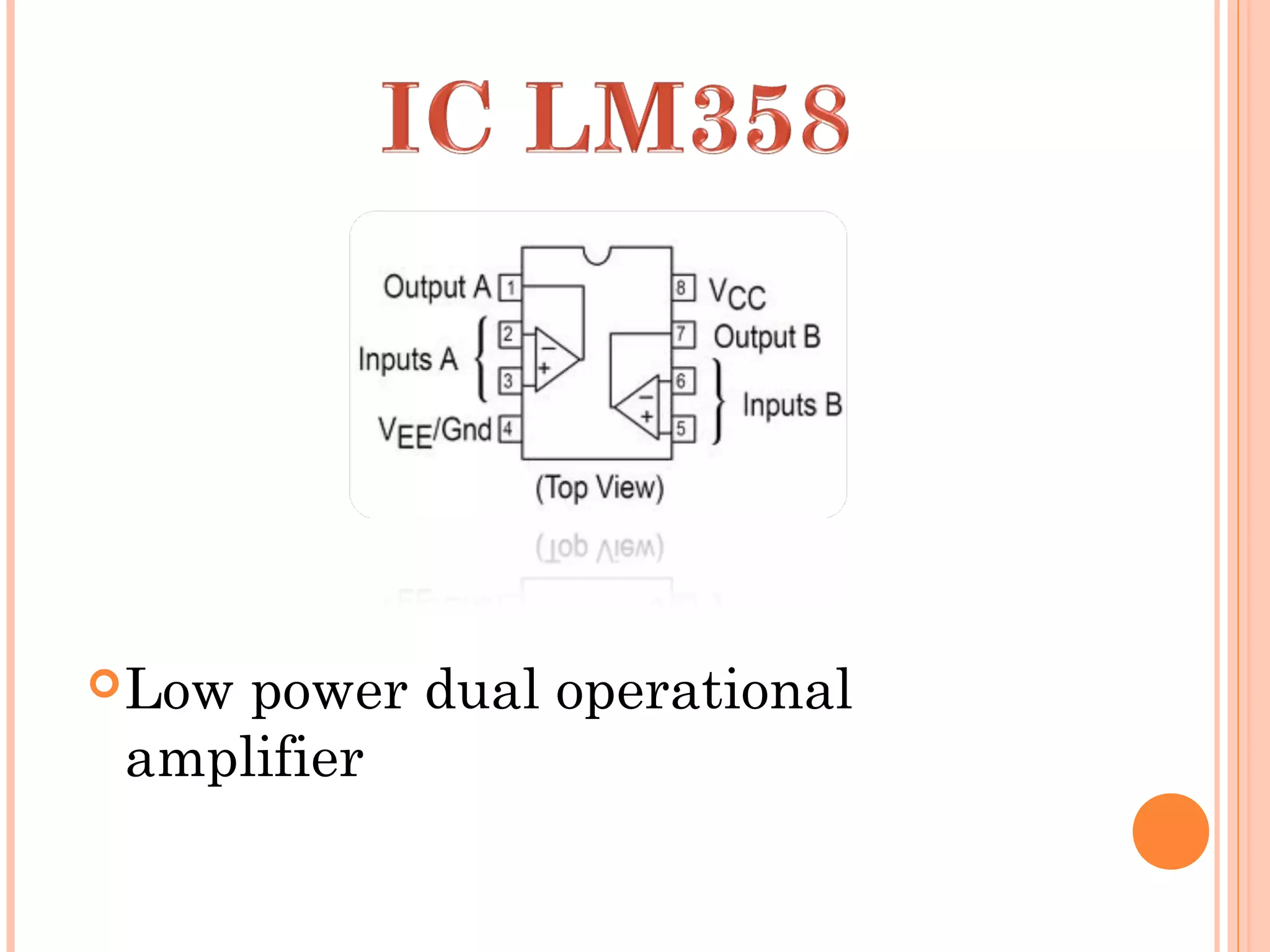
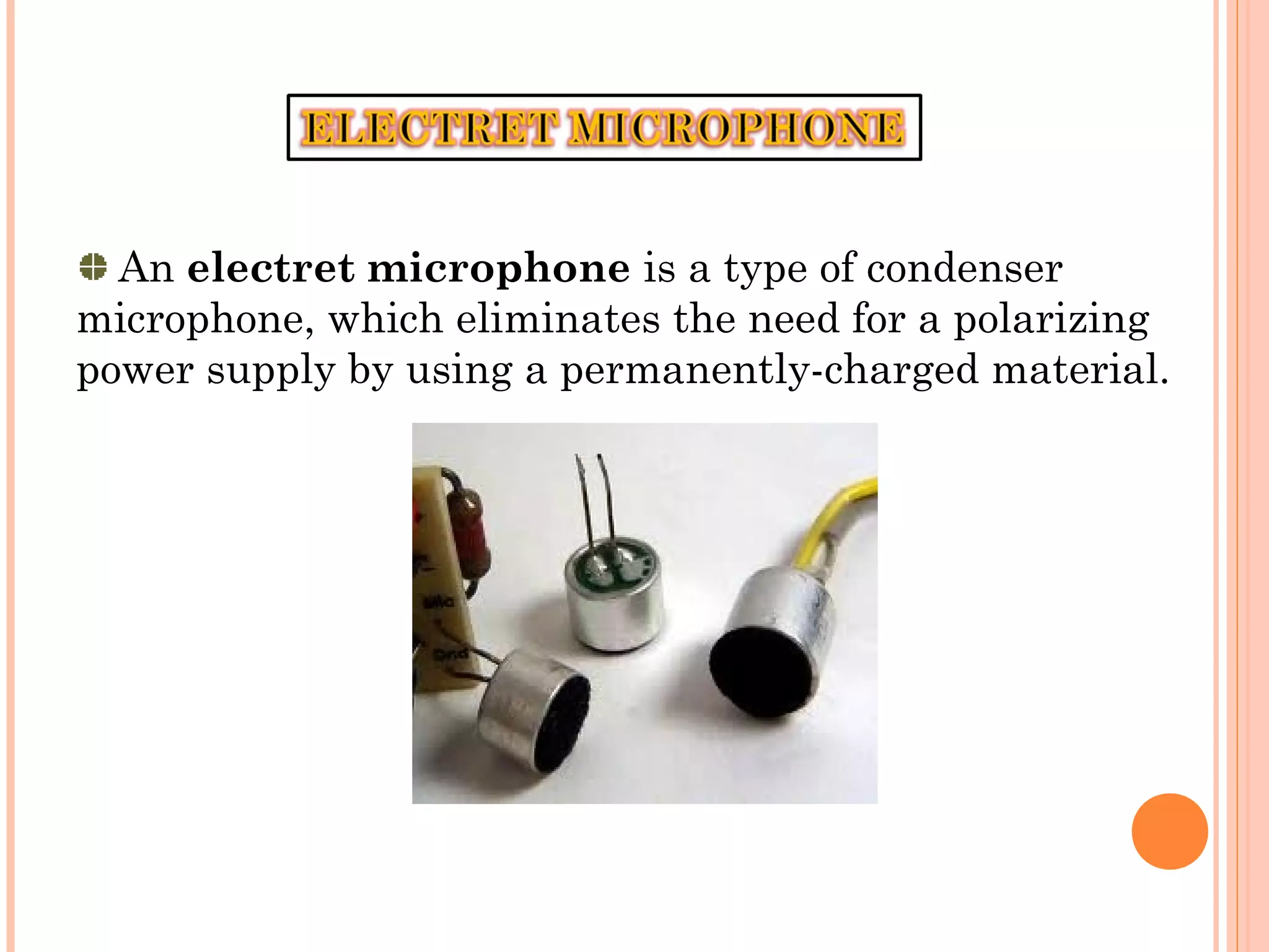
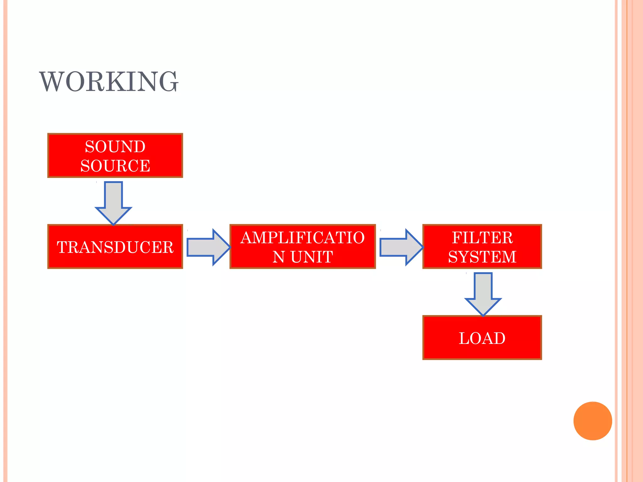
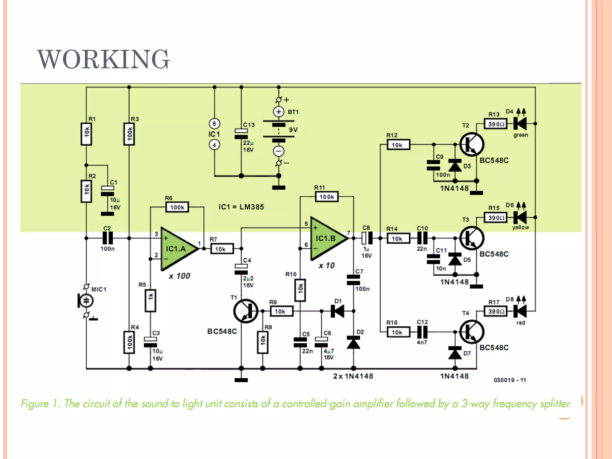
Submitted to :-
Ms. VARSHA DRABLA
Ms. AARTI SHARMA
Submitted by :-
HARISH KUMAWAT
session : 2010-11
A sound to light system converts music
signals into light pulses.
 base channel indicate the ‘beat’ of the
music by a more or less rhythmical flash,
while the other two represent the higher
frequency ranges of the music channel.
The ‘private’ version of a sound to light
system employs three colored LEDs
instead of powerful flashing lights or
floodlights as used in most discos.
 Another peculiarity of the circuit is the automatic
sensitivity adaptation to the music volume detected. In
this way, the circuit can work without any control.
 The circuit always draws an average current of 20 mA
and works happily off a 9V PP3 block battery.
The objective of this project is to generate the
light patterns in rhythmic manner.
A music-to-light modulator is a circuit which
controls the intensity of one or more lights in
response to an audio input.
Arguably there’s no less pleasure in enjoying
dance music in the privacy of your home, study or
students digs.
However, the true disco feeling is not obtained
without a matching sound to light unit, so here’s a
really smaller version.
Low power dual operational
amplifier
FEATURES OF LM 358
can be directly operated off of the standard +5V power
supply voltage.
Wide power supply range:
Very low supply current drain (500 µA)-essentially
independent of supply voltage
Low input offset voltage: 2 mV
Differential input voltage range equal to the power
supply voltage
Large output voltage swing.
Wide bandwidth (unity gain): 1 MHz
A microphone is an acoustic-to-electric transducer or
sensor that converts sound into an electrical signal.
used in many applications such as telephones, tape
recorders, karaoke systems, hearing aids, motion picture
production, live and recorded audio engineering,
An electret microphone is a type of condenser
microphone, which eliminates the need for a polarizing
power supply by using a permanently-charged material.
WORKING
SOUND
SOURCE
FILTER
SYSTEM
LOAD
AMPLIFICATIO
N UNIT
TRANSDUCER
WORKING
 We have employed two operational amplifiers with the
total gain of 1000 times.
 The input of the first op-amp is connected to the
electret microphone capsules via capacitor C2.
 microphone is given a certain DC bias level obtained
from the 9V supply rail by resistors R1 and R2.
 Capacitor C2, then, ensures that the microphone bias
level does not appear at the op-amp input.
WORKING…
WORKING….
It means, it will only pass the alternating component,
which is caused by the sound picked up by the
microphone.
Because of the two resistors have same value, the
supply voltage is effectively halved, i.e., 4.5V exists at
the junction of R3 and R4.
This bias voltage will also exists at the output of the
first op-amp and, because of R7, at the input of the
second one also, whose output will also copy this DC
level.
In this way, R3 and R4 keep boththe op-amps biased
at half the supply voltage.
First op-amp has a gain of 100 while the second op-
amp has a gain of about 10.
WORKING…
 signal level at the output of first op-amp is
rectified by diodes D1 and D2, smoothed by C6 and
then used to drive n-p-n transistor T1.
FILTERS:-
consist of simple RC network…........
Fc = 1/(2πRC) Hz
low-pass section R12/C9 is dimensioned for about 160
Hz using 10Ω (R12) and 100 nF (C9).
To prevent the transistor bases from being charged
with negative levels, anti parallel diodes (D3, D5, D7) are
used on each base terminal
 Cell phone background lights for rhythmic
flashing according to the ringtone or incoming
call alert.
 In disco and party lounges.
  In music players and amplifiers.
  Simple sound-to-light unit for music,
 Sound indicator.
 For the hearing impaired : can be used to
indicate the telephone
 Door bell.
 In musical fountains.
 Less no. of LEDs are used..
 Circuitry is complex.
 Can only be used at small scale.
 by increasing the number of LEDs used.
 can be used at a large scale for commercial
purposes such as in discos, parties, etc.
 LEDs in the system is replaced by the large light
sources such as bulbs.
 fluorescent lamps can also used to save
consumption, in place of bulbs.
 increasing the number of filters used in the
system.
sound to light  system

sound to light system

  • 1.
    Submitted to :- Ms.VARSHA DRABLA Ms. AARTI SHARMA Submitted by :- HARISH KUMAWAT session : 2010-11
  • 2.
    A sound tolight system converts music signals into light pulses.  base channel indicate the ‘beat’ of the music by a more or less rhythmical flash, while the other two represent the higher frequency ranges of the music channel. The ‘private’ version of a sound to light system employs three colored LEDs instead of powerful flashing lights or floodlights as used in most discos.
  • 3.
     Another peculiarityof the circuit is the automatic sensitivity adaptation to the music volume detected. In this way, the circuit can work without any control.  The circuit always draws an average current of 20 mA and works happily off a 9V PP3 block battery.
  • 4.
    The objective ofthis project is to generate the light patterns in rhythmic manner. A music-to-light modulator is a circuit which controls the intensity of one or more lights in response to an audio input. Arguably there’s no less pleasure in enjoying dance music in the privacy of your home, study or students digs. However, the true disco feeling is not obtained without a matching sound to light unit, so here’s a really smaller version.
  • 5.
    Low power dualoperational amplifier
  • 6.
    FEATURES OF LM358 can be directly operated off of the standard +5V power supply voltage. Wide power supply range: Very low supply current drain (500 µA)-essentially independent of supply voltage Low input offset voltage: 2 mV Differential input voltage range equal to the power supply voltage Large output voltage swing. Wide bandwidth (unity gain): 1 MHz
  • 7.
    A microphone isan acoustic-to-electric transducer or sensor that converts sound into an electrical signal. used in many applications such as telephones, tape recorders, karaoke systems, hearing aids, motion picture production, live and recorded audio engineering,
  • 8.
    An electret microphoneis a type of condenser microphone, which eliminates the need for a polarizing power supply by using a permanently-charged material.
  • 9.
  • 10.
  • 11.
     We haveemployed two operational amplifiers with the total gain of 1000 times.  The input of the first op-amp is connected to the electret microphone capsules via capacitor C2.  microphone is given a certain DC bias level obtained from the 9V supply rail by resistors R1 and R2.  Capacitor C2, then, ensures that the microphone bias level does not appear at the op-amp input. WORKING…
  • 12.
    WORKING…. It means, itwill only pass the alternating component, which is caused by the sound picked up by the microphone. Because of the two resistors have same value, the supply voltage is effectively halved, i.e., 4.5V exists at the junction of R3 and R4. This bias voltage will also exists at the output of the first op-amp and, because of R7, at the input of the second one also, whose output will also copy this DC level. In this way, R3 and R4 keep boththe op-amps biased at half the supply voltage. First op-amp has a gain of 100 while the second op- amp has a gain of about 10.
  • 13.
    WORKING…  signal levelat the output of first op-amp is rectified by diodes D1 and D2, smoothed by C6 and then used to drive n-p-n transistor T1.
  • 14.
    FILTERS:- consist of simpleRC network…........ Fc = 1/(2πRC) Hz low-pass section R12/C9 is dimensioned for about 160 Hz using 10Ω (R12) and 100 nF (C9). To prevent the transistor bases from being charged with negative levels, anti parallel diodes (D3, D5, D7) are used on each base terminal
  • 16.
     Cell phonebackground lights for rhythmic flashing according to the ringtone or incoming call alert.  In disco and party lounges.   In music players and amplifiers.   Simple sound-to-light unit for music,  Sound indicator.  For the hearing impaired : can be used to indicate the telephone  Door bell.  In musical fountains.
  • 17.
     Less no.of LEDs are used..  Circuitry is complex.  Can only be used at small scale.
  • 18.
     by increasingthe number of LEDs used.  can be used at a large scale for commercial purposes such as in discos, parties, etc.  LEDs in the system is replaced by the large light sources such as bulbs.  fluorescent lamps can also used to save consumption, in place of bulbs.  increasing the number of filters used in the system.