Learning Outcomes
ENGG08002: Computeraided Design
At the end of this module the student will be able to:
L1. Characterise and employ appropriate advanced solid geometry feature creation
methods and techniques.
L2. Develop basic parametric relationships in the model creation process.
L3. Configure product assembly using various assembly constraints.
L4. Produce drawings, describing various product design details.
3.
Module Introduction
ENGG08002: Computeraided Design
Assessment Summary
Assessment Category 1: Coursework - 2 @ 50% each
•A minimum of 30% must be obtained for each element of
assessment.
•A minimum of 40% is required to achieve a pass in the
module.
Element Release date Submission Date Weighting
Course work 1 50%
Course work 2 50%
100%
4.
Introduction to Facilitiesand Pro/ENGINEER Concepts
ENGG08002: Computer aided Design
Module Introduction
Introduction to Facilities
Pro/ENGINEER Concepts
Creating Sketcher Geometry
5.
Pro/ENGINEER Concepts
Solid Models:
Arerealistic visual representation of designs.
Contain properties such as mass, volume,
and center of gravity.
Can also be used to check for interferences
in an assembly.
ENGG08002: Computer aided Design
Pro/ENGINEER Concepts
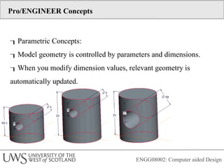
Parametric Concepts:
Modelgeometry is controlled by parameters and dimensions.
When you modify dimension values, relevant geometry is
automatically updated.
ENGG08002: Computer aided Design
8.
Pro/ENGINEER Concepts
Associative Concepts:
Bi-directionalassociativity means that all
changes made to an object in any mode of
Pro/ENGINEER are automatically reflected in
every related mode.
For example, a change made in a drawing
is reflected in the part being documented in
the drawing. That same change is also
reflected in every assembly using that part
model.
ENGG08002: Computer aided Design
9.
Pro/ENGINEER Concepts
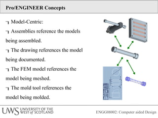
Model-Centric:
Assemblies referencethe models
being assembled.
The drawing references the model
being documented.
The FEM model references the
model being meshed.
The mold tool references the
model being molded.
ENGG08002: Computer aided Design
Pro/ENGINEER Concepts
Main Interface:
sWindow — The working area of
Pro/ENGINEER
Main Menu
Toolbars
Message Window
Dashboard
Dialog Boxes
Menu Manager
Drawing Ribbon — A context-sensitive menu
ENGG08002: Computer aided Design
12.
Pro/ENGINEER Concepts
Folder Browseris divided into:
Common Folders, Folder Tree
A window must be active to use all applicable
Pro/ENGINEER features.
The word Active appears on the title bar of
the active window next to the model name.
The active model has a dot next to its name in the
Window menu.
ENGG08002: Computer aided Design
13.
Pro/ENGINEER Concepts
Setting theWorking Directory:
Pro/ENGINEER is started in the default working
directory.
Different working directories can be set.
New working directory locations are not
saved upon exiting Pro/ENGINEER.
ENGG08002: Computer aided Design
14.
Pro/ENGINEER Concepts
Basic Display
Options
Datum Planes
Datum Axes
Datum Points
Coordinate Systems
Shaded
No Hidden
Hidden Line
Wireframe
ENGG08002: Computer aided Design
Pro/ENGINEER Concepts
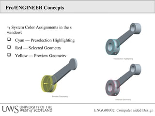
System ColorAssignments in the s
window:
Cyan — Preselection Highlighting
Red — Selected Geometry
Yellow — Preview Geometry
ENGG08002: Computer aided Design
17.
ENGG08002: Computer aidedDesign
Pro/ENGINEER Concepts
The model tree enables you to:
Visualize model features.
Visualize feature order.
Select items.
Edit items.
Use model tree filters to control both item
and feature type display
18.
Pro/ENGINEER Concepts
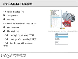
You candirect select:
Components
Features
You can perform direct selection in:
The s window
The model tree
Select multiple items using CTRL.
Select a range of items using SHIFT.
Selection filter provides various
filters
19.
Pro/ENGINEER Concepts
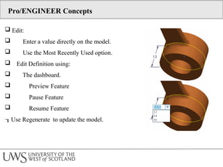
Edit:
Enter a value directly on the model.
Use the Most Recently Used option.
Edit Definition using:
The dashboard.
Preview Feature
Pause Feature
Resume Feature
Use Regenerate to update the model.
20.
Pro/ENGINEER Concepts
Deletingand Suppressing Items:
Delete:
Is permanent.
Follows Parent/Child Rels.
Suppress:
Items can be restored via Resume.
Follows Parent/Child Rels.
Resume:
Selected items.
All items.
21.
Pro/ENGINEER Concepts
EditingFeature and Component Visibility:
Hide/Unhide:
Components in an assembly
Datum features
Solid features
Does not affect parent/child relationships.
Changes are not saved by default.
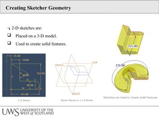
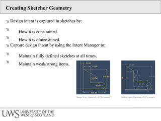
Creating Sketcher Geometry
Designintent is captured in sketches by:
How it is constrained.
How it is dimensioned.
Capture design intent by using the Intent Manager to:
Maintain fully defined sketches at all times.
Maintain weak/strong items.
24.
Creating Sketcher Geometry
The following display options are available in Sketcher:
Dimensions
Constraints
Grid
Section vertices
Sketch Orientation reorients parallel to the screen.