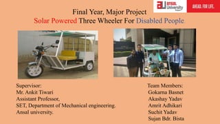
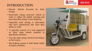
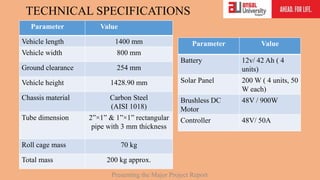
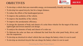
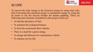
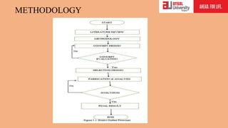
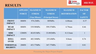
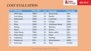
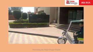
Final Year, Major Project
Solar Powered Three Wheeler For Disabled
People.
Department of Mechanical Engineering,
Ansal University, Gurgaon
Final Year, Major Project
Solar Powered Three Wheeler For Disabled People.
Supervisor: Team Members:
Mr. Ankit Tiwari Gokarna Basnet
Assistant Professor, Akashay Yadav
SET, Department of Mechanical engineering. Amrit Adhikari
Ansal university. Suchit Yadav
Sujan Bdr. Bista
OVERVIEW
• Abstract
• Introduction
• Objectives
• Scope
• Methodology
• Result and Discussion
• Conclusion
• Reference
Presenting the Major Project Report
ABSTRACT
Nowadays, transportation is an inseparable part of human daily life. People can travel one
place to another easily utilizing different means of transportations when it comes to the
disabled person, it is quite challenging to travel from one place to another due to their
different disabilities. Hence, in this project, we have focused on developing the three
wheeler for the disabled person having disabilities related to their arm or legs. As three
wheeler being cheap means of transportation as well as it is easier to control. An effort has
been directed to design a lightweight, high strength, and ergonomic solar powered three
wheeler. Sustainable Mobility issues are gaining increasing attention both among specialists
and in public opinion, due to the major impact of automotive systems on carbon dioxide
production, climate changes, and fossil fuel depletion. So, the solar energy is the best
solution for the source of energy for this project. The proposed model is powered with 900
W, 48 V DC Brushless motor. The 48V, 168AH battery act as energy storage which is
charged by the solar panels. The structural model of the three-wheeler was designed in
Solidworks CAD software. Structural and weight analysis were performed to select the
right material for the frame so as to build a vehicle which would be very lightweight but
strong enough to sustain high loads exerted by the driver during a ride. The analysis was
performed on the ANSYS Multiphysics software.
Presenting the Major Project Report
INTRODUCTION
• Electric Vehicle Powered by Solar
Energy.
• Renewable energy powered vehicle in
order to reduce the global warming and
non renewable energy source depletion.
• Especially built aiming to individuals
who have impairments that limit their
ability to walk.
• It typically consists of a seat supported
on three large wheels attached in
spaceframe structure.
• Uses the solar energy stored in the battery
as fuel source.
• Has braking system in both hands unlike
in battery rickshaw.
Presenting the Major Project Report
TECHNICAL SPECIFICATIONS
Parameter Value
Vehicle length 1400 mm
Vehicle width 800 mm
Ground clearance 254 mm
Vehicle height 1428.90 mm
Chassis material Carbon Steel
(AISI 1018)
Tube dimension 2”×1” & 1”×1” rectangular
pipe with 3 mm thickness
Roll cage mass 70 kg
Total mass 200 kg approx.
Parameter Value
Battery 12v/ 42 Ah ( 4
units)
Solar Panel 200 W ( 4 units, 50
W each)
Brushless DC
Motor
48V / 900W
Controller 48V/ 50A
Presenting the Major Project Report
OBJECTIVES
• To develop a vehicle that uses renewable energy, environmentally friendly and cheap.
• To develop low-speed tricycle, but for a longer distance.
• To reduce the efforts of the handicapped person.
• To improve the aesthetics of the vehicle.
• To improve the durability of the vehicle.
• To improve the aerodynamic efficiency.
• To design the elements of body and chassis of a solar three wheeler for the target of the most
lightweight and lowest material cost design.
• To analyze the elements of body and chassis of a solar car.
• To fabricate the solar car than can withstand the load from the solar panel body, driver, and
also the suspension.
• To develop an electrical tri-wheel vehicle that can charge the battery when it is not in used.
• To develop an electrical tricycle that can charge the battery when it is not in used.
Presenting the Major Project Report
SCOPE
To convert the solar energy to the electrical energy by using solar cells,
then Converting this electrical energy to mechanical energy by using the
dc motor to run the tricycle besides the human paddling. There are
following main elements considered in this project which are:
• To find the alternative of fuel.
• To maintain the ecological balance.
• To form the economical three wheeler.
• There is a need for a green energy.
• To design and fabricate low maintenance vehicle.
• To enhance service life.
Presenting the Major Project Report
METHODOLOGY
CONCEPTUAL DESIGN
The Initial Conceptual design of the three wheeler, which we observe generally around
us and keeping in mind, our project requirements. The initial design was sketched doing,
brainstorming among the team members.
Presenting the Major Project Report
CAD DESIGN OF VEHICLE
Presenting the Major Project Report
MARKET SURVEY
• The three wheeler needs various parts like Rectangular tube, differentials, DC motors,
solar panels, Batteries etc. To use the optimum resources with optimum budget, we did
market survey for the various components.
Shop Name /Address Material purchased Cost
S.N steels, Sikenderpur Mild steel rectangular
tube
8000/-
Ananda autoparts, Delhi Battery Ricksaw KIT 18000/-
Kuber Fiber Gallery, Sikenderpur Fibre Sheet 2000/-
Gaia Energy Solutions Pvt. Ltd, Chandni Chowk Solar Panel 8000/-
Aster India Battery House, Old Gurgaon Battery 8400/-
Other Miscellaneous 8100/-
Presenting the Major Project Report
PIPE CUTTING
Presenting the Major Project Report
The pipe of designed length and parameters are cut with the help of
Grinding wheel. The cross section of rectangular pipes are 2”×1” and 1”×1”
are cut according the required length as per designed requirements.
WELDING
The Pipes thus cut are joined using the electric arc-welding to make the designed
frame structure of the vehicle.
The chassis frame consists of 2”×1” rectangular pipe having 3mm thickness,
whereas remaining structure uses 1”×1” square pipe having 3mm thickness.
Presenting the Major Project Report
FINISHED FULL BODY STRUCTURE AFTER WELDING
Presenting the Major Project Report
CALCULATIONS INVOLVED:
Power requirement of vehicle at particular speed:
P = F*v
F= Frolling + Fair resistance + Fgrade
F = mgRr + 0.5ρair Cd Af v2 +mgsinө
Where, m= 200 kg Rr=0.02 Cd=0.25 ρair= 1.2 kg/m3 Af= 1.5 m2 V= 30 km/hr = 8.33 m/s
So, F= 200*9.81*0.02 + 0.5*1.2*0.25*1.5*8.332 + 200*9.81*sin5о
F = 54.85 N
P= F*V = 54.85*8.33 = 456.90W ≈ 500W
Battery capacity:
Battery load= 900w
Let the power factor (PF) = 0.8
Now VA for corresponding load requirement be
VA=
𝑊
𝑃𝐹
=
900
0.8
=1125 VA System voltage= 48v Current (I) =
1125
48
=23.43 amp
Amp-Hr. = 23.43*4 (considering the vehicle to run 4hrs) = 93.75 AH
Presenting the Major Project Report
SHEET METAL
Sheet metal is use to give the aesthetic and to cover up the space between the frame.
It is use to hold the various parts of the vehicle such as Batteries, controller etc. it is
fixed by screws with drilling in the rectangular pipe structure.
Presenting the Major Project Report
VARIOUS PARTS USED IN VEHICLE
Presenting the Major Project Report
Solar Panels Controller Battery
DC Motor
Throttle
Differential
ASSEMBLING VARIOUS PARTS
Presenting the Major Project Report
COLOURING/PAINTING
Initially the vehicle is painted with primer and finally painted with white paint. The initial and final looks of the
vehicle are presented below:
Presenting the Major Project Report
FINITE ELEMENT ANALYSIS
After finalizing the frame along with its material and cross section, it is very
essential to test the rigidity and strength of the frame under severe conditions. The
frame should be able to withstand the impact, torsion, roll over conditions and
provide utmost safety to the driver without undergoing much deformation.
Following tests were performed on the roll cage-
Front impact,
Side impact,
Rear impact,
 Roll Over.
Torsional Rigidity.
Presenting the Major Project Report
Loading condition and constraints for Finite Element Analysis
FACTOR OF SAFETY: ALWAYS CONSIDERED FOR THIS DESIGN BETWEEN 0.5 – 1 ACCORDING TO
THE ANALYSIS RESULTS.
Estimated mass of vehicle=200 kg
Let, G=Estimated mass of vehicle × g
Where, g= acceleration due to gravity ≈ 10 m/s2
Hence, G=200 × 10 = 2000 N
TESTS FRONT
IMPACT
SIDE
IMPACT
ROLL OVER REAR
IMPACT
TORSIONAL
CONSTRAINTS REAR
CORNERS(ALL
DOF=0);
SUSPENSION
MOUNTINGS
(Uy,Uz=0)
OPPOSITE
SIM
MEMBERS(A
LL DOF=0)
LFS
MEMBERS
(ALL DOF=0)
FRONT
CORNERS(A
LL DOF=0);
SUSPENSIO
N
MOUNTING
S(Uy, Uz=0)
REAR CORNERS (
ALL DOF=0, UX, UY
=0 )
LOADS 4G 6G 2G 4G 1G
Presenting the Major Project Report
1) Front impact analysis
Impact load calculation:
• Using the projected vehicle/driver mass of 200 kg, the impact force was calculated base on a
G-load of 4 for extremely worst condition.
• F = ma = 200*10*4 = 8000 N
• Impact Time = weight*(velocity/load)
= 200*(8.33/8000) = 0.20 seconds
Presenting the Major Project Report
2) Rear impact analysis
• Using the projected vehicle/driver mass of 200 kg, the impact force was calculated base
on a G-load of 4 for extremely worst condition.
• F = ma = 200*10*4 = 8000 N
• Impact Time= weight*(velocity/load)
= 200*(8.33/8000) = 0.20 seconds
Presenting the Major Project Report
3) Side impact Analysis
Impact load calculation:
• Using the projected vehicle/driver mass of 200 kg, the impact force was calculated base
on a G-load of 6 for extremely worst condition.
• F = ma
= 200*6*10=12000N
Presenting the Major Project Report
4) Roll Over Analysis
Impact load calculation:
• Using the projected vehicle/driver mass of 200 kg, the impact force was calculated base on a
G-load of 2 for extremely worst condition.
• F = ma = 200*2*10 = 4000N
Presenting the Major Project Report
5) Torsional Rigidity Analysis
Impact load calculation:
Using the projected vehicle/driver mass of 200 kg, the impact force was calculated base on
a G-load of 1.
F = ma = 200*1*10 = 2000N
Presenting the Major Project Report
APPLIED
FORCE
MAXIMUM
STRESS
(Von-Misses)
MAXIMUM
STRESS
(Principal Stress)
MAXIMUM
DEFORMATION
FACTOR
OF
SAFETY
FRONT
IMPACT
8000N 974.2MPa 889MPa 6.08mm 0.37
REAR
IMPACT
8000N 539.98MPa 599.57MPa 4.79mm 0.46
SIDE
IMPACT
12000N 48.851MPa 33.092MPa 0.113mm 1
ROLL
OVER
4000N 483.54MPa 255.6MPa 0.8mm 0.76
TORSIONAL
RIGIDITY
2000N 453.77MPa 347.77MPa 2.433 0.81
RESULTS
Presenting the Major Project Report
CONCLUSION
• From this Project, we can conclude that this vehicle is quite suitable
for almost all the humans. By referring to above advantages, the
vehicle is affordable to middle-class person also, because the cost of
the vehicle is optimum.
• As the current increasing volume of car transportation rising the
health problem as well as environmental issues, hence this vehicle
focus the technology that enables the manufacturing, launching and
sustainable implementation of 3 wheel battery operated shuttle
vehicle in Indian market.
Presenting the Major Project Report
COST EVALUATION
Presenting the Major Project Report
S/N Materials Price (Rs) S/N Materials Price (Rs)
1 ERW pipes 5000/- 13 Drum brake 230/-
2 Leaf spring 1200/- 14 Handle 120/-
3 Differential 3000/- 15 Controller 1900/-
4 Tyres 1800/- 16 Charger 2000/-
5 Rims 1060/- 17 Aluminum sheets 2600/-
6 Wiring 1200/- 18 Batteries 9500/-
7 Motor 2500/- 19 Screws 200/-
8 Solar Panels 7000/- 20 Brake cables 200/-
9 Fibre sheets 1350/- 21. Paint 750/-
10 Lightening 1300/- 22. Welding 2500/-
11 Suspension 950/- 23. Miscellaneous 6000/-
12 Front axle 100/- 24. Total 52,500/-
FUTURE WORK
• We can also provide the leg steering system for those who are disabled in term of
arms.
• The efficiency of this vehicle can be raised by adding solar panel or alternator to
charge batteries. By enforcing the alternator in the vehicle, we can charge batteries
during traveling. So there is no need to charge batteries frequently.
• As we are well known that the sources of fossil fuels are going to vanish in next
few decades, hence the electric bike will experience the period of boom. Hence we
can say that this vehicle may have very bright future.
Presenting the Major Project Report
REFERENCES
• M. Reddi Sankar, T. Pushpaveni, V. Bhanu Prakash Reddy, “Design and Development of Solar Assisted Bicycle.” International Journal of Scientific and
Research Publications, (Volume 3, Issue 3), (March 2013), ISSN 2250-3153
• N.Sasikumar (Ph.D(Part-Time) Research Scholar, Kamban Arts & Science College, Coimbatore), Dr. P. Jayasubramaniam (Head & Asst.Prof. in
Professional Accounting, Dr. N.G.P. Arts & Science College, Coimbatore). “Solar Energy System in India.” IOSR Journal of Business and Management
(IOSR-JBM) ISSN: 2278-487X. Volume 7, Issue 1 (Jan- Feb 2013), (Page No. 61-68)
• Abdulkadir Baba Hassan (Department of Mechanical Engineering, Federal University of Technology, Minna, Niger State, Nigeria), “Design and
Fabrication of Motorized Prototype Tricycle For the Disable Persons.” IOSR Journal of Engineering, (Volume 2(5)), May 2012, (Page No.1071-1074).
• Yogesh sunil wamborikar, Abhay Sinha,“Solar powered vehicle”. Proceedings of the World Congress on Engineering and Computer Science 2010 Vol II
WCECS 2010, October 20-22, 2010, San Francisco, USA, ISBN: 978-988-18210-0-3
• Arun Manohar Gurram, P.S.V Ramana Rao, Raghuveer Dontikurti “Solar Powered Wheel Chair: Mobility for Physically Challenged” International
Journal of Current Engineering and Technology Volume 2, No.1 (March 2012) ISSN 2277 – 4106 (Page No. 211-214)
• Shuh Jing Ying, Stephen Sundarrao. “Power Assist Hand Tricycle with Battery for Disabled Persons” International Journal of Advanced Technology in
Engineering and Science Volume 02, Issue No. 06, June 2014 ISSN (online): 2348 – 7550 (Page No. 173-177)
• Chetan mahadik, sumit Mahindra Kar, prof. Jayashree deka,“An improved & efficient electric bicycle system with the power of real-time information
sharing”, Multidisciplinary Journal of Research in Engineering and Technology, Volume 1, Issue 2, Pg.215-222
• Qingfeng su, genfa zhang, jianming lai, shijun feng, and weimin shi, “Green solar electric vehicle changing the future lifestyle of human”. World
Electric Vehicle Journal Vol. 4 - ISSN 2032-6653 - © 2010 WEVA
• Satish Kumar Dwivedi, Deepak Kumar Yadav, Ashutosh Mishra, Madhusudan Jaiswal, Shrikant Singh, Sujeet Kumar , (Department of Mechanical
Engineering, Buddha Institute of Technology, Gorakhpur,U.P).“Design and Fabrication of a Motorized Tricycle for Physically Challenged Persons”
International Journal of Engineering Science Invention, ISSN (Online): 2319 – 6734, ISSN (Print): 2319 – 6726 April 2014 Volume 3 (Page No. 29-32)
• Solar Electricity calculation handbook by Michael Boxwell.
Presenting the Major Project Report

Solar three wheeler for disabled person

  • 1.
    Final Year, MajorProject Solar Powered Three Wheeler For Disabled People. Department of Mechanical Engineering, Ansal University, Gurgaon
  • 2.
    Final Year, MajorProject Solar Powered Three Wheeler For Disabled People. Supervisor: Team Members: Mr. Ankit Tiwari Gokarna Basnet Assistant Professor, Akashay Yadav SET, Department of Mechanical engineering. Amrit Adhikari Ansal university. Suchit Yadav Sujan Bdr. Bista
  • 3.
    OVERVIEW • Abstract • Introduction •Objectives • Scope • Methodology • Result and Discussion • Conclusion • Reference Presenting the Major Project Report
  • 4.
    ABSTRACT Nowadays, transportation isan inseparable part of human daily life. People can travel one place to another easily utilizing different means of transportations when it comes to the disabled person, it is quite challenging to travel from one place to another due to their different disabilities. Hence, in this project, we have focused on developing the three wheeler for the disabled person having disabilities related to their arm or legs. As three wheeler being cheap means of transportation as well as it is easier to control. An effort has been directed to design a lightweight, high strength, and ergonomic solar powered three wheeler. Sustainable Mobility issues are gaining increasing attention both among specialists and in public opinion, due to the major impact of automotive systems on carbon dioxide production, climate changes, and fossil fuel depletion. So, the solar energy is the best solution for the source of energy for this project. The proposed model is powered with 900 W, 48 V DC Brushless motor. The 48V, 168AH battery act as energy storage which is charged by the solar panels. The structural model of the three-wheeler was designed in Solidworks CAD software. Structural and weight analysis were performed to select the right material for the frame so as to build a vehicle which would be very lightweight but strong enough to sustain high loads exerted by the driver during a ride. The analysis was performed on the ANSYS Multiphysics software. Presenting the Major Project Report
  • 5.
    INTRODUCTION • Electric VehiclePowered by Solar Energy. • Renewable energy powered vehicle in order to reduce the global warming and non renewable energy source depletion. • Especially built aiming to individuals who have impairments that limit their ability to walk. • It typically consists of a seat supported on three large wheels attached in spaceframe structure. • Uses the solar energy stored in the battery as fuel source. • Has braking system in both hands unlike in battery rickshaw. Presenting the Major Project Report
  • 6.
    TECHNICAL SPECIFICATIONS Parameter Value Vehiclelength 1400 mm Vehicle width 800 mm Ground clearance 254 mm Vehicle height 1428.90 mm Chassis material Carbon Steel (AISI 1018) Tube dimension 2”×1” & 1”×1” rectangular pipe with 3 mm thickness Roll cage mass 70 kg Total mass 200 kg approx. Parameter Value Battery 12v/ 42 Ah ( 4 units) Solar Panel 200 W ( 4 units, 50 W each) Brushless DC Motor 48V / 900W Controller 48V/ 50A Presenting the Major Project Report
  • 7.
    OBJECTIVES • To developa vehicle that uses renewable energy, environmentally friendly and cheap. • To develop low-speed tricycle, but for a longer distance. • To reduce the efforts of the handicapped person. • To improve the aesthetics of the vehicle. • To improve the durability of the vehicle. • To improve the aerodynamic efficiency. • To design the elements of body and chassis of a solar three wheeler for the target of the most lightweight and lowest material cost design. • To analyze the elements of body and chassis of a solar car. • To fabricate the solar car than can withstand the load from the solar panel body, driver, and also the suspension. • To develop an electrical tri-wheel vehicle that can charge the battery when it is not in used. • To develop an electrical tricycle that can charge the battery when it is not in used. Presenting the Major Project Report
  • 8.
    SCOPE To convert thesolar energy to the electrical energy by using solar cells, then Converting this electrical energy to mechanical energy by using the dc motor to run the tricycle besides the human paddling. There are following main elements considered in this project which are: • To find the alternative of fuel. • To maintain the ecological balance. • To form the economical three wheeler. • There is a need for a green energy. • To design and fabricate low maintenance vehicle. • To enhance service life. Presenting the Major Project Report
  • 9.
  • 10.
    CONCEPTUAL DESIGN The InitialConceptual design of the three wheeler, which we observe generally around us and keeping in mind, our project requirements. The initial design was sketched doing, brainstorming among the team members. Presenting the Major Project Report
  • 11.
    CAD DESIGN OFVEHICLE Presenting the Major Project Report
  • 12.
    MARKET SURVEY • Thethree wheeler needs various parts like Rectangular tube, differentials, DC motors, solar panels, Batteries etc. To use the optimum resources with optimum budget, we did market survey for the various components. Shop Name /Address Material purchased Cost S.N steels, Sikenderpur Mild steel rectangular tube 8000/- Ananda autoparts, Delhi Battery Ricksaw KIT 18000/- Kuber Fiber Gallery, Sikenderpur Fibre Sheet 2000/- Gaia Energy Solutions Pvt. Ltd, Chandni Chowk Solar Panel 8000/- Aster India Battery House, Old Gurgaon Battery 8400/- Other Miscellaneous 8100/- Presenting the Major Project Report
  • 13.
    PIPE CUTTING Presenting theMajor Project Report The pipe of designed length and parameters are cut with the help of Grinding wheel. The cross section of rectangular pipes are 2”×1” and 1”×1” are cut according the required length as per designed requirements.
  • 14.
    WELDING The Pipes thuscut are joined using the electric arc-welding to make the designed frame structure of the vehicle. The chassis frame consists of 2”×1” rectangular pipe having 3mm thickness, whereas remaining structure uses 1”×1” square pipe having 3mm thickness. Presenting the Major Project Report
  • 15.
    FINISHED FULL BODYSTRUCTURE AFTER WELDING Presenting the Major Project Report
  • 16.
    CALCULATIONS INVOLVED: Power requirementof vehicle at particular speed: P = F*v F= Frolling + Fair resistance + Fgrade F = mgRr + 0.5ρair Cd Af v2 +mgsinө Where, m= 200 kg Rr=0.02 Cd=0.25 ρair= 1.2 kg/m3 Af= 1.5 m2 V= 30 km/hr = 8.33 m/s So, F= 200*9.81*0.02 + 0.5*1.2*0.25*1.5*8.332 + 200*9.81*sin5о F = 54.85 N P= F*V = 54.85*8.33 = 456.90W ≈ 500W Battery capacity: Battery load= 900w Let the power factor (PF) = 0.8 Now VA for corresponding load requirement be VA= 𝑊 𝑃𝐹 = 900 0.8 =1125 VA System voltage= 48v Current (I) = 1125 48 =23.43 amp Amp-Hr. = 23.43*4 (considering the vehicle to run 4hrs) = 93.75 AH Presenting the Major Project Report
  • 17.
    SHEET METAL Sheet metalis use to give the aesthetic and to cover up the space between the frame. It is use to hold the various parts of the vehicle such as Batteries, controller etc. it is fixed by screws with drilling in the rectangular pipe structure. Presenting the Major Project Report
  • 18.
    VARIOUS PARTS USEDIN VEHICLE Presenting the Major Project Report Solar Panels Controller Battery DC Motor Throttle Differential
  • 19.
    ASSEMBLING VARIOUS PARTS Presentingthe Major Project Report
  • 20.
    COLOURING/PAINTING Initially the vehicleis painted with primer and finally painted with white paint. The initial and final looks of the vehicle are presented below: Presenting the Major Project Report
  • 21.
    FINITE ELEMENT ANALYSIS Afterfinalizing the frame along with its material and cross section, it is very essential to test the rigidity and strength of the frame under severe conditions. The frame should be able to withstand the impact, torsion, roll over conditions and provide utmost safety to the driver without undergoing much deformation. Following tests were performed on the roll cage- Front impact, Side impact, Rear impact,  Roll Over. Torsional Rigidity. Presenting the Major Project Report
  • 22.
    Loading condition andconstraints for Finite Element Analysis FACTOR OF SAFETY: ALWAYS CONSIDERED FOR THIS DESIGN BETWEEN 0.5 – 1 ACCORDING TO THE ANALYSIS RESULTS. Estimated mass of vehicle=200 kg Let, G=Estimated mass of vehicle × g Where, g= acceleration due to gravity ≈ 10 m/s2 Hence, G=200 × 10 = 2000 N TESTS FRONT IMPACT SIDE IMPACT ROLL OVER REAR IMPACT TORSIONAL CONSTRAINTS REAR CORNERS(ALL DOF=0); SUSPENSION MOUNTINGS (Uy,Uz=0) OPPOSITE SIM MEMBERS(A LL DOF=0) LFS MEMBERS (ALL DOF=0) FRONT CORNERS(A LL DOF=0); SUSPENSIO N MOUNTING S(Uy, Uz=0) REAR CORNERS ( ALL DOF=0, UX, UY =0 ) LOADS 4G 6G 2G 4G 1G Presenting the Major Project Report
  • 23.
    1) Front impactanalysis Impact load calculation: • Using the projected vehicle/driver mass of 200 kg, the impact force was calculated base on a G-load of 4 for extremely worst condition. • F = ma = 200*10*4 = 8000 N • Impact Time = weight*(velocity/load) = 200*(8.33/8000) = 0.20 seconds Presenting the Major Project Report
  • 24.
    2) Rear impactanalysis • Using the projected vehicle/driver mass of 200 kg, the impact force was calculated base on a G-load of 4 for extremely worst condition. • F = ma = 200*10*4 = 8000 N • Impact Time= weight*(velocity/load) = 200*(8.33/8000) = 0.20 seconds Presenting the Major Project Report
  • 25.
    3) Side impactAnalysis Impact load calculation: • Using the projected vehicle/driver mass of 200 kg, the impact force was calculated base on a G-load of 6 for extremely worst condition. • F = ma = 200*6*10=12000N Presenting the Major Project Report
  • 26.
    4) Roll OverAnalysis Impact load calculation: • Using the projected vehicle/driver mass of 200 kg, the impact force was calculated base on a G-load of 2 for extremely worst condition. • F = ma = 200*2*10 = 4000N Presenting the Major Project Report
  • 27.
    5) Torsional RigidityAnalysis Impact load calculation: Using the projected vehicle/driver mass of 200 kg, the impact force was calculated base on a G-load of 1. F = ma = 200*1*10 = 2000N Presenting the Major Project Report
  • 28.
    APPLIED FORCE MAXIMUM STRESS (Von-Misses) MAXIMUM STRESS (Principal Stress) MAXIMUM DEFORMATION FACTOR OF SAFETY FRONT IMPACT 8000N 974.2MPa889MPa 6.08mm 0.37 REAR IMPACT 8000N 539.98MPa 599.57MPa 4.79mm 0.46 SIDE IMPACT 12000N 48.851MPa 33.092MPa 0.113mm 1 ROLL OVER 4000N 483.54MPa 255.6MPa 0.8mm 0.76 TORSIONAL RIGIDITY 2000N 453.77MPa 347.77MPa 2.433 0.81 RESULTS Presenting the Major Project Report
  • 29.
    CONCLUSION • From thisProject, we can conclude that this vehicle is quite suitable for almost all the humans. By referring to above advantages, the vehicle is affordable to middle-class person also, because the cost of the vehicle is optimum. • As the current increasing volume of car transportation rising the health problem as well as environmental issues, hence this vehicle focus the technology that enables the manufacturing, launching and sustainable implementation of 3 wheel battery operated shuttle vehicle in Indian market. Presenting the Major Project Report
  • 30.
    COST EVALUATION Presenting theMajor Project Report S/N Materials Price (Rs) S/N Materials Price (Rs) 1 ERW pipes 5000/- 13 Drum brake 230/- 2 Leaf spring 1200/- 14 Handle 120/- 3 Differential 3000/- 15 Controller 1900/- 4 Tyres 1800/- 16 Charger 2000/- 5 Rims 1060/- 17 Aluminum sheets 2600/- 6 Wiring 1200/- 18 Batteries 9500/- 7 Motor 2500/- 19 Screws 200/- 8 Solar Panels 7000/- 20 Brake cables 200/- 9 Fibre sheets 1350/- 21. Paint 750/- 10 Lightening 1300/- 22. Welding 2500/- 11 Suspension 950/- 23. Miscellaneous 6000/- 12 Front axle 100/- 24. Total 52,500/-
  • 31.
    FUTURE WORK • Wecan also provide the leg steering system for those who are disabled in term of arms. • The efficiency of this vehicle can be raised by adding solar panel or alternator to charge batteries. By enforcing the alternator in the vehicle, we can charge batteries during traveling. So there is no need to charge batteries frequently. • As we are well known that the sources of fossil fuels are going to vanish in next few decades, hence the electric bike will experience the period of boom. Hence we can say that this vehicle may have very bright future. Presenting the Major Project Report
  • 32.
    Presenting the MajorProject Report
  • 33.
    REFERENCES • M. ReddiSankar, T. Pushpaveni, V. Bhanu Prakash Reddy, “Design and Development of Solar Assisted Bicycle.” International Journal of Scientific and Research Publications, (Volume 3, Issue 3), (March 2013), ISSN 2250-3153 • N.Sasikumar (Ph.D(Part-Time) Research Scholar, Kamban Arts & Science College, Coimbatore), Dr. P. Jayasubramaniam (Head & Asst.Prof. in Professional Accounting, Dr. N.G.P. Arts & Science College, Coimbatore). “Solar Energy System in India.” IOSR Journal of Business and Management (IOSR-JBM) ISSN: 2278-487X. Volume 7, Issue 1 (Jan- Feb 2013), (Page No. 61-68) • Abdulkadir Baba Hassan (Department of Mechanical Engineering, Federal University of Technology, Minna, Niger State, Nigeria), “Design and Fabrication of Motorized Prototype Tricycle For the Disable Persons.” IOSR Journal of Engineering, (Volume 2(5)), May 2012, (Page No.1071-1074). • Yogesh sunil wamborikar, Abhay Sinha,“Solar powered vehicle”. Proceedings of the World Congress on Engineering and Computer Science 2010 Vol II WCECS 2010, October 20-22, 2010, San Francisco, USA, ISBN: 978-988-18210-0-3 • Arun Manohar Gurram, P.S.V Ramana Rao, Raghuveer Dontikurti “Solar Powered Wheel Chair: Mobility for Physically Challenged” International Journal of Current Engineering and Technology Volume 2, No.1 (March 2012) ISSN 2277 – 4106 (Page No. 211-214) • Shuh Jing Ying, Stephen Sundarrao. “Power Assist Hand Tricycle with Battery for Disabled Persons” International Journal of Advanced Technology in Engineering and Science Volume 02, Issue No. 06, June 2014 ISSN (online): 2348 – 7550 (Page No. 173-177) • Chetan mahadik, sumit Mahindra Kar, prof. Jayashree deka,“An improved & efficient electric bicycle system with the power of real-time information sharing”, Multidisciplinary Journal of Research in Engineering and Technology, Volume 1, Issue 2, Pg.215-222 • Qingfeng su, genfa zhang, jianming lai, shijun feng, and weimin shi, “Green solar electric vehicle changing the future lifestyle of human”. World Electric Vehicle Journal Vol. 4 - ISSN 2032-6653 - © 2010 WEVA • Satish Kumar Dwivedi, Deepak Kumar Yadav, Ashutosh Mishra, Madhusudan Jaiswal, Shrikant Singh, Sujeet Kumar , (Department of Mechanical Engineering, Buddha Institute of Technology, Gorakhpur,U.P).“Design and Fabrication of a Motorized Tricycle for Physically Challenged Persons” International Journal of Engineering Science Invention, ISSN (Online): 2319 – 6734, ISSN (Print): 2319 – 6726 April 2014 Volume 3 (Page No. 29-32) • Solar Electricity calculation handbook by Michael Boxwell. Presenting the Major Project Report
  • 34.
    Presenting the MajorProject Report