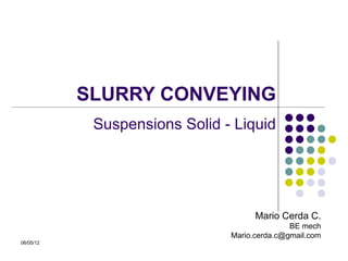

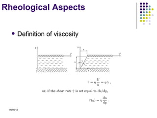
![Settling Velocity Models
.
Durand - Condolios
Durand
VC = FL 2 gD( S − 1)
Durand modified by Juan Rayo
VC = 1.25 ⋅ FL [ 2 gD( S − 1) ]
0.25
Mc Elvain - Cave
Wasp
1
d 50 6
VC = 3.116C 0.186
V 2 gD( S − 1)
D
06/05/12](https://image.slidesharecdn.com/slurry-conveying-en-120505201754-phpapp02/85/Slurry-conveying-13-320.jpg)

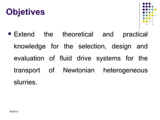
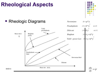
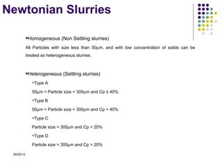
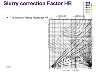
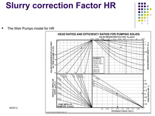
![Slurry correction Factor HR
McElvain & Cave model for HR
K × Cv
HR = 1 -
20
where:
K S
K = K ( S, d 50 ) 0.50 8.00
0.45 5.00
4.00
0.40
3.00
0.35 2.55
0.30
2.00
0.25
1.80
0.20
0.15 1.25
0.10
1.10
0.05
0.00
0.01 0.1 1.0 10.0
06/05/12
D50 [mm]](https://image.slidesharecdn.com/slurry-conveying-en-120505201754-phpapp02/85/Slurry-conveying-19-320.jpg)
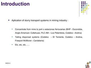
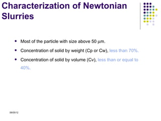
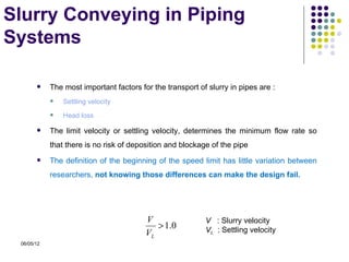
![Cerda Model for HR & FL
Limite settling velocity factor (FL)
[ ] [
Fl = 1.4Cv0.045 + ( 0.18 + 0.006 ln ( Cv ) ) ln ( d 50 ) * 0.042d 50 − 0.218d 50 + 0.265d 50 + .96
3 2
]
Slurry correction factor HR & ER
HR = a( c ln( d 50 ) + d ) + 1
where :
a = −0.1605C p + .000466
ρs
b=
ρl
c = 0.0133b 3 − 0.1785b 2 + 1.0555b − 0.8232
d = .04630b 3 − 0.6361b 2 + 3.8714b − 2.9632
06/05/12](https://image.slidesharecdn.com/slurry-conveying-en-120505201754-phpapp02/85/Slurry-conveying-22-320.jpg)
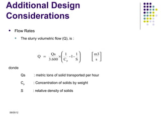
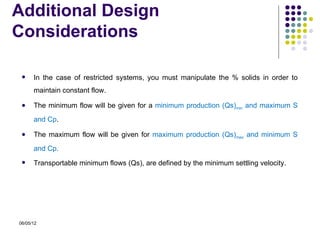

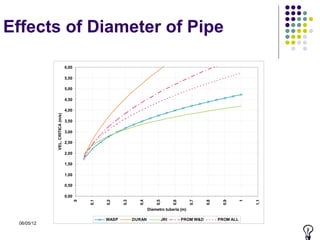
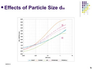
This document discusses slurry conveying systems used in mining applications to transport mining waste and concentrates. It covers Newtonian slurries characterized by small particle sizes and low concentrations. Key aspects summarized include rheological models for viscosity, methods for calculating settling velocity, and steps to design a slurry transport system, including characterizing flows, determining pipe diameter, head losses, and pump selection. Slurry transport is affected by particle size, concentration, and pipe diameter, with minimum flow rates defined by settling velocity limits.


