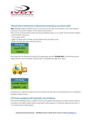
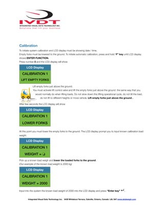
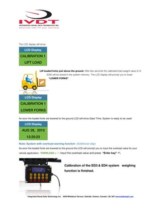
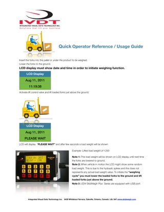
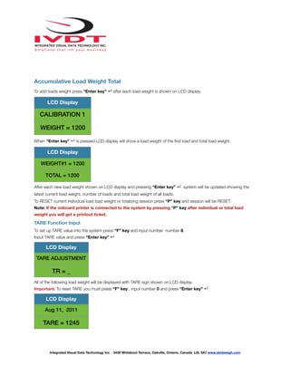
This document provides instructions for installing and calibrating the ED3/ED4 SkidWeigh Plus on-board check weighing system. It describes the key components, installation process, and calibration procedure. The calibration involves lifting empty and known-weight loaded forks above the ground to automatically set the system's weight readings. Proper electrical and pressure transducer connections are verified with an initial load reading before full calibration is performed.
Anda perlu produk Pasutri? - masalah kesehatan wanita?
Hanya ada disini... Bisnis Online dengan FULL Support System!.. Binsnis Online 100% dari rumah.
Bergabung bersama kami di AbeNetwork.
Kunjungi: http://www.bisnisharmonis.com/topstar
Anda perlu produk Pasutri? - masalah kesehatan wanita?
Hanya ada disini... Bisnis Online dengan FULL Support System!.. Binsnis Online 100% dari rumah.
Bergabung bersama kami di AbeNetwork.
Kunjungi: http://www.bisnisharmonis.com/topstar
Fully automatic detection of material handling vehicles idling with identification of downtime reasons, visual feedback to operator of current operational status
We as project management professionals are well aware of the importance of the so-called "soft skills" in our professional development and success.
But what exactly are these skills and why are they important in our profession?
How can we determine when these skills are to be used and what can we do to maximize our effectiveness in each individual area?
Attendees to this presentation will learn:
1) The 15 Essential Soft Skills of Project Management Professionals.
2) Practical situations and examples where these skills are demonstrated.
3) Exercises and best practices designed to improve their skill level in each area.
What are the differences between project and program management? How are they similar? What strategies are necessary for a successful transition from one to the other?
This presentation will address those questions and in addition provide practical guide lines and tips to those individuals aspiring be successful program managers as well as organizations that are in transition.
What is your Project Management Leadership style? This presentation explores different styles displayed in the movie, "Lord of the Rings". Is your leadership style presented? Do you recognize the leadership style of a fellow PM?.
SkidFleet, Lift Truck Fleet Operational Management Information SystemTed Jurca
SkidFleet wireless connects your entire material handling fleet, capturing vehicle and operator data to provide operational insights about your activities unreal time
"Impact of front-end architecture on development cost", Viktor TurskyiFwdays
I have heard many times that architecture is not important for the front-end. Also, many times I have seen how developers implement features on the front-end just following the standard rules for a framework and think that this is enough to successfully launch the project, and then the project fails. How to prevent this and what approach to choose? I have launched dozens of complex projects and during the talk we will analyze which approaches have worked for me and which have not.
Connector Corner: Automate dynamic content and events by pushing a buttonDianaGray10
Here is something new! In our next Connector Corner webinar, we will demonstrate how you can use a single workflow to:
Create a campaign using Mailchimp with merge tags/fields
Send an interactive Slack channel message (using buttons)
Have the message received by managers and peers along with a test email for review
But there’s more:
In a second workflow supporting the same use case, you’ll see:
Your campaign sent to target colleagues for approval
If the “Approve” button is clicked, a Jira/Zendesk ticket is created for the marketing design team
But—if the “Reject” button is pushed, colleagues will be alerted via Slack message
Join us to learn more about this new, human-in-the-loop capability, brought to you by Integration Service connectors.
And...
Speakers:
Akshay Agnihotri, Product Manager
Charlie Greenberg, Host
UiPath Test Automation using UiPath Test Suite series, part 4DianaGray10
Welcome to UiPath Test Automation using UiPath Test Suite series part 4. In this session, we will cover Test Manager overview along with SAP heatmap.
The UiPath Test Manager overview with SAP heatmap webinar offers a concise yet comprehensive exploration of the role of a Test Manager within SAP environments, coupled with the utilization of heatmaps for effective testing strategies.
Participants will gain insights into the responsibilities, challenges, and best practices associated with test management in SAP projects. Additionally, the webinar delves into the significance of heatmaps as a visual aid for identifying testing priorities, areas of risk, and resource allocation within SAP landscapes. Through this session, attendees can expect to enhance their understanding of test management principles while learning practical approaches to optimize testing processes in SAP environments using heatmap visualization techniques
What will you get from this session?
1. Insights into SAP testing best practices
2. Heatmap utilization for testing
3. Optimization of testing processes
4. Demo
Topics covered:
Execution from the test manager
Orchestrator execution result
Defect reporting
SAP heatmap example with demo
Speaker:
Deepak Rai, Automation Practice Lead, Boundaryless Group and UiPath MVP
GDG Cloud Southlake #33: Boule & Rebala: Effective AppSec in SDLC using Deplo...James Anderson
Effective Application Security in Software Delivery lifecycle using Deployment Firewall and DBOM
The modern software delivery process (or the CI/CD process) includes many tools, distributed teams, open-source code, and cloud platforms. Constant focus on speed to release software to market, along with the traditional slow and manual security checks has caused gaps in continuous security as an important piece in the software supply chain. Today organizations feel more susceptible to external and internal cyber threats due to the vast attack surface in their applications supply chain and the lack of end-to-end governance and risk management.
The software team must secure its software delivery process to avoid vulnerability and security breaches. This needs to be achieved with existing tool chains and without extensive rework of the delivery processes. This talk will present strategies and techniques for providing visibility into the true risk of the existing vulnerabilities, preventing the introduction of security issues in the software, resolving vulnerabilities in production environments quickly, and capturing the deployment bill of materials (DBOM).
Speakers:
Bob Boule
Robert Boule is a technology enthusiast with PASSION for technology and making things work along with a knack for helping others understand how things work. He comes with around 20 years of solution engineering experience in application security, software continuous delivery, and SaaS platforms. He is known for his dynamic presentations in CI/CD and application security integrated in software delivery lifecycle.
Gopinath Rebala
Gopinath Rebala is the CTO of OpsMx, where he has overall responsibility for the machine learning and data processing architectures for Secure Software Delivery. Gopi also has a strong connection with our customers, leading design and architecture for strategic implementations. Gopi is a frequent speaker and well-known leader in continuous delivery and integrating security into software delivery.
Accelerate your Kubernetes clusters with Varnish CachingThijs Feryn
A presentation about the usage and availability of Varnish on Kubernetes. This talk explores the capabilities of Varnish caching and shows how to use the Varnish Helm chart to deploy it to Kubernetes.
This presentation was delivered at K8SUG Singapore. See https://feryn.eu/presentations/accelerate-your-kubernetes-clusters-with-varnish-caching-k8sug-singapore-28-2024 for more details.
Essentials of Automations: Optimizing FME Workflows with ParametersSafe Software
Are you looking to streamline your workflows and boost your projects’ efficiency? Do you find yourself searching for ways to add flexibility and control over your FME workflows? If so, you’re in the right place.
Join us for an insightful dive into the world of FME parameters, a critical element in optimizing workflow efficiency. This webinar marks the beginning of our three-part “Essentials of Automation” series. This first webinar is designed to equip you with the knowledge and skills to utilize parameters effectively: enhancing the flexibility, maintainability, and user control of your FME projects.
Here’s what you’ll gain:
- Essentials of FME Parameters: Understand the pivotal role of parameters, including Reader/Writer, Transformer, User, and FME Flow categories. Discover how they are the key to unlocking automation and optimization within your workflows.
- Practical Applications in FME Form: Delve into key user parameter types including choice, connections, and file URLs. Allow users to control how a workflow runs, making your workflows more reusable. Learn to import values and deliver the best user experience for your workflows while enhancing accuracy.
- Optimization Strategies in FME Flow: Explore the creation and strategic deployment of parameters in FME Flow, including the use of deployment and geometry parameters, to maximize workflow efficiency.
- Pro Tips for Success: Gain insights on parameterizing connections and leveraging new features like Conditional Visibility for clarity and simplicity.
We’ll wrap up with a glimpse into future webinars, followed by a Q&A session to address your specific questions surrounding this topic.
Don’t miss this opportunity to elevate your FME expertise and drive your projects to new heights of efficiency.
Essentials of Automations: Optimizing FME Workflows with Parameters
Skid weigh plus v1.15 Series
1. !
Installation & Calibration
!
ED3/ED4 SkidWeigh Plus Series
Lift Truck On-board Check Weighing Systems
Version:ED3- V1.15
Integrated Visual Data Technology Inc. 3439 Whilabout Terrace, Oakville, Ontario, Canada L6L 0A7 www.skidweigh.com
Version: ED3/ED4 V 1.15
2. !
General Installation Guide
This ED3 & ED4 SkidWeigh Plus, Version:1.15 Series installation & calibration guide describes how to install, calibrate,
test and use your on-board check weighing unit. Following the instructions in this guide will enable you to get your
system operating quickly and easily. In the event that you require additional assistance, please contact customer support
via e-mail at support@skidweigh.com , visit www.skidweigh.com or contact us at the address or contact number below:
Integrated Visual Data Technology Inc.
3439 Whilabout Terrace, Oakville, ON, Canada, L6L 0A7
Phone: 905-469-0985
Safety
Always disconnect the vehicle battery while installing SkidWeigh system or any other electronic product.
Make sure sure that unit, pressure transducer and any other associated cables are securely mounted and do not impede
any of the vehicle’s controls. Use care when routing the components cables. Route the cables where they will be
protected. Use commonly accepted install practices for after market industrial vehicle electronic devices.
The installation of the SkidWeigh systems should only be performed by an acknowledged lift truck dealer technician or
end user electro and hydraulic technical installer.
Here are two acceptable methods of making a wire connections:
* Soldering your connections (recommended)
* Crimp connectors ( with the use of the proper crimping tool)
Regardless of the method you choose, ensure that the connection is mechanically sound and properly insulated. Use
high quality electrical tape and shrink tubing where necessary.
This product is connected directly to the vehicle’s ignition switch, 12 to 55 V DC. There is no on-off switch on the unit.
Electro-Magnetic Compatibility
CE conformity to EC directive 89/336 (EMC) by application of harmonized standards: Interference stability EN 61000-6-2
and EN 61326-1 interference emit EN 61000-6-3, EN 61326-1 for the pressure transducer.
ED3 SkidWeigh Plus Series
Our policy is one of continuous improvement and the information in this document is subject to change without notice.
Check that software version displayed on LCD is the one applicable for your application.
Overview of components
The standard ED3 SkidWeigh Plus check weighing system consist of two main components:
* Digital indicator with wiring harness, mounting bracket and anti-vibration mount
* Hydraulic pressure transducer with 3 wires cable
* Installation & calibration manual and operator usage instruction
Integrated Visual Data Technology Inc. 3439 Whilabout Terrace, Oakville, Ontario, Canada L6L 0A7 www.skidweigh.com
3. !
Operational principal
The ED3 SkidWeigh Plus operational principal is based on the hydraulic pressure transducer mounted in the vehicle lifting
hydraulic circuit that will automatically activate the “weighing cycle / specific algorithm ” every time a skid load is lifted just
above the ground. The increase in pressure is converted in an electronic signal at the sample rate of 16000 readings
which is converted into a load weight reading.
Pressure transducer installation
The pressure transducer must be installed in the lifting hydraulic line between the lift control valve and lift
cylinder(s). Mount a T-piece in hydraulic line. In some cases you can install the pressure transducer in the flow divider,
drilling and tapping for 1/4”-18 NPT male in spare plug (if only single or double mast configuration) or in the body of the
flow divider. Also, you can drill and tap on any “larger elbow” that might be available in the hydraulic lifting circuit found
in vehicles with larger hoses to accommodate larger vehicle lifting capacities.
Pressure transducer installation precautions
Before installation of the pressure transducer the hydraulic lift circuit must be pressure free.
There are two ways to do that:
1. Place the forks on the ground in their lowest position and
make the hydraulic system pressure free by tilting the mast
forward. The chain(s) should be slack.
2. Lift the forks and position them on the top of a supporting
fixture. Start lowering the lifting cylinder into its lowest position.
Be sure that chain(s) are slack.
Make sure that that installed pressure transducer will not touch
any moving parts or assembly of the vehicle while in normal
operation. Pressure transducer has 1/4”-18 NPT male thread.
Use thread seal to ensure tight fit.
Selecting the mounting location for digital indicator
Use the mounting bracket with the anti vibration mount and fasten digital indicator on the vehicle dashboard or side
railing preferably on the right hand side. There are many examples of mounting locations that will depend on the vehicle
model. However, additional mounting items such as a flat brackets may be needed to help secure the unit to upper right
corner of the guard or side railing.
Choose the correct location and make sure that:
- Indicator is visible and within reach of the operator
- Location so that operator does not hit a head
Integrated Visual Data Technology Inc. 3439 Whilabout Terrace, Oakville, Ontario, Canada L6L 0A7 www.skidweigh.com
4. !
Compact size
All of the SkidWeigh systems are compact, housing dimension of only 120
x 80 x 55 mm is ideal for the installations to material handling vehicles of
all kinds.
Electrical connections
All SkidWeigh systems operate from 12 to 55 V DC.
Digital indicator five wires single cable
- Orange Wire (+) Ignition switch On position
- Brown Wire (-) Battery negative
- Red Wire, connect to RED wire of the pressure transducer cable
- Black Wire, connect to BLACK wire of the pressure transducer
cable
- White Wire, connect to WHITE wire of the pressure transducer
cable
Pressure transducer cable
- White Wire, signal 0 to 2,5 V
- Black Wire, signal negative
- Red Wire, power supply + 11 V DC
Power short circuit protection
All SkidWeigh systems are internally short circuit protected with resettable fuse. There is no need to install external inline
fuse in orange wire connected to the ignition switch.
Note: Any external devices connected to the SkidWeigh system, such as non standard onboard printer might require
external fuse.
Integrated Visual Data Technology Inc. 3439 Whilabout Terrace, Oakville, Ontario, Canada L6L 0A7 www.skidweigh.com
5. !
“Quick test to determine if electrical connections are done right”
Note: SkidWeigh weighing calibration function is not done yet at this stage. This procedure is only to test if electrical
connections of the system installation into the vehicle is done properly!
After you have connected electrical power and pressure transducer cable you can “quickly” check the system operation.
- Lower the forks to the ground
- Turn On ignition switch
- Digital LCD display will be activated, showing software version and serial number
- Digital LCD display will show current date and time
If the loaded forks are lifted above the ground LCD digital display will show “PLEASE WAIT” and within few seconds
display will show “some” load weight . (Example: 455, not calibrated load weight at this stage)
If the above test is valid than the system electrical connections are done right. The next procedure will be to calibrate the
SkidWeigh weighing function.
Lift truck equipped with hydraulic accumulators
If the standard SkidWeigh system is installed on the lift trucks equipped with hydraulic accumulators, please contact us
to provide you with different digital indicator having specific software algorithm to obtain load weight accuracy within +/-
1% of vehicle maximum lifting capacity.
LCD Display
Aug 28, 2010
12:20:23
LCD Display
PLEASE WEIGHT
WEIGHT = 455
Integrated Visual Data Technology Inc. 3439 Whilabout Terrace, Oakville, Ontario, Canada L6L 0A7 www.skidweigh.com
6. !
Date / Time Set Up
In the event that date and time is not right you can correct when you press F key and hold it for the moment until LCD
display shows ENTER FUNCTION
Press number 3 and display will be in date / time change mode.
Use left ◀ and right ▶ arrow key (bottom left side of the keypad) to change the
value. Press “Enter key” ↵ (bottom right side keypad arrow) to confirm the
setting. The cursor will automatically move to the next item to be changed ( Month,
Day, Year, Hours, Minutes, Seconds). On the last correction, seconds item press
“Enter key” ↵ to confirm new date / time set up.
Weighing calibration
The ED3 & ED4 SkidWeigh Plus calibration is automatic and is done by lifting empty and loaded forks (or any other
attachment such as paper clamp) just above the ground. MAKE SURE THAT YOU HAVE A KNOWN LOAD WEIGHT
AND KEEP IT NEARBY TO COMPLETE THE CALIBRATION.
For the best results use at least minimum calibration load test weight of 30 to 50% of maximum lifting capacity of the lift
truck. Use customer floor scale or find a known skid load weight within the operational facility.
Important:
If you want the system to show load weight in pounds, use the known load weight in pounds and
enter that value accordingly. The same would apply if you want the system to show load weight in
kilograms. Use the known load weight in kilograms and enter that value into the system
accordingly.
Calibration starting point
Lower the empty forks to the ground. There should be no hydraulic pressure in lift hydraulic circuit.
- Turn ignition switch to on position (electric lift trucks) and start the engine on combustion powered lift trucks
- LCD display will show software version and serial number for the moment and date and time will be displayed
LCD Display
AUG 28, 2010
12:20:23
Integrated Visual Data Technology Inc. 3439 Whilabout Terrace, Oakville, Ontario, Canada L6L 0A7 www.skidweigh.com
7. !
Calibration
To initiate system calibration and LCD display must be showing date / time.
Empty forks must be lowered to the ground. To initiate automatic calibration, press and hold “F” key until LCD display
shows ENTER FUNCTION.
Press number 0 and the LCD display will show
Lift empty forks just above the ground.
You must activate lift control valve and lift the empty forks just above the ground the same way that you
would normally do when lifting loads. Do not slow down this lifting operational cycle, do not tilt the load,
do not lift to different heights or move vehicle. Lift empty forks just above the ground .
After few seconds the LCD display will show
At this point you must lower the empty forks to the ground. The LCD display prompt you to input known calibration load
weight.
Pick up a known load weigh and lower the loaded forks to the ground.
(Our example of the known load weight is 2000 kg)
Input into the system the known load weight of 2000 into the LCD display and press “Enter key” ↵.
LCD Display
CALIBRATION 1
LIFT EMPTY FORKS
LCD Display
CALIBRATION 1
LOWER FORKS
LCD Display
CALIBRATION 1
WEIGHT = ❏
LCD Display
CALIBRATION 1
WEIGHT = 2000
Integrated Visual Data Technology Inc. 3439 Whilabout Terrace, Oakville, Ontario, Canada L6L 0A7 www.skidweigh.com
8. !
The LCD display will show
Lift loaded forks just above the ground. After few seconds the calibrated load weight value of of
2000 will be stored in the system memory. The LCD display will prompt you to lower
“LOWER FORKS”.
As soon the loaded forks are lowered to the ground LCD will show Data/ Time. System is ready to be used!
Note: System with overload warning function (Additional step)
As soon the loaded forks are lowered to the ground the LCD will prompt you to input the overload value for your
vehicle application. “OVERLOAD = -“. Input the overload value and press “Enter key” ↵.
Calibration of the ED3 & ED4 system weighing
function is finished.
LCD Display
CALIBRATION 1
LIFT LOAD
LCD Display
CALIBRATION 1
LOWER FORKS
LCD Display
AUG 28, 2010
12:25:23
Integrated Visual Data Technology Inc. 3439 Whilabout Terrace, Oakville, Ontario, Canada L6L 0A7 www.skidweigh.com
9. !
Quick Operator Reference / Usage Guide
Insert the forks into the pallet or under the product to be weighed.
Lower the forks to the ground.
LCD display must show date and time in order to initiate weighing function.
Activate lift control valve and lift loaded forks just above the ground.
LCD will display “PLEASE WAIT” and after few seconds a load weight will be shown
Example: Lifted load weight of 1200
Note 1: This load weight will be shown on LCD display until next time
the forks are lowered to ground.
Note 2: When vehicle in motion the LCD might show some random
load weight. This is due to the hydraulic spikes and this does not
represents any actual load weight value. To initiate the “weighing
cycle” you must lower the loaded forks to the ground and lift
loaded forks just above the ground.
Note 3 : ED4 SkidWeigh Plus Series are equipped with USB port.
LCD Display
Aug 11, 2011
11:19:38
LCD Display
Aug 11, 2011
PLEASE WAIT
Integrated Visual Data Technology Inc. 3439 Whilabout Terrace, Oakville, Ontario, Canada L6L 0A7 www.skidweigh.com
10. !
Accumulative Load Weight Total
To add loads weight press “Enter key” ↵ after each load weight is shown on LCD display.
When “Enter key” ↵ is pressed LCD display will show a load weight of the first load and total load weight.
After each new load weight shown on LCD display and pressing “Enter key” ↵ system will be updated showing the
latest current load weight, number of loads and total load weight of all loads.
To RESET current individual load load weight or totalizing session press “P” key and session will be RESET.
Note: If the onboard printer is connected to the system by pressing “P” key after individual or total load
weight you will get a printout ticket.
TARE Function Input
To set up TARE value into the system press “F” key and input number number 8.
Input TARE value and press “Enter key” ↵
All of the following load weight will be displayed with TARE sign shown on LCD display.
Important: To reset TARE you must press “F” key , input number 0 and press “Enter key” ↵.
LCD Display
CALIBRATION 1
WEIGHT = 1200
LCD Display
WEIGHT#1 = 1200
TOTAL = 1200
LCD Display
TARE ADJUSTMENT
TR = _
LCD Display
Aug 11, 2011
TARE = 1245
Integrated Visual Data Technology Inc. 3439 Whilabout Terrace, Oakville, Ontario, Canada L6L 0A7 www.skidweigh.com