SkidFleet, Lift Truck Fleet Operational Management Information SystemTed Jurca
SkidFleet wireless connects your entire material handling fleet, capturing vehicle and operator data to provide operational insights about your activities unreal time
UiPath Test Automation using UiPath Test Suite series, part 4DianaGray10
Welcome to UiPath Test Automation using UiPath Test Suite series part 4. In this session, we will cover Test Manager overview along with SAP heatmap.
The UiPath Test Manager overview with SAP heatmap webinar offers a concise yet comprehensive exploration of the role of a Test Manager within SAP environments, coupled with the utilization of heatmaps for effective testing strategies.
Participants will gain insights into the responsibilities, challenges, and best practices associated with test management in SAP projects. Additionally, the webinar delves into the significance of heatmaps as a visual aid for identifying testing priorities, areas of risk, and resource allocation within SAP landscapes. Through this session, attendees can expect to enhance their understanding of test management principles while learning practical approaches to optimize testing processes in SAP environments using heatmap visualization techniques
What will you get from this session?
1. Insights into SAP testing best practices
2. Heatmap utilization for testing
3. Optimization of testing processes
4. Demo
Topics covered:
Execution from the test manager
Orchestrator execution result
Defect reporting
SAP heatmap example with demo
Speaker:
Deepak Rai, Automation Practice Lead, Boundaryless Group and UiPath MVP
Builder.ai Founder Sachin Dev Duggal's Strategic Approach to Create an Innova...Ramesh Iyer
In today's fast-changing business world, Companies that adapt and embrace new ideas often need help to keep up with the competition. However, fostering a culture of innovation takes much work. It takes vision, leadership and willingness to take risks in the right proportion. Sachin Dev Duggal, co-founder of Builder.ai, has perfected the art of this balance, creating a company culture where creativity and growth are nurtured at each stage.
Slack (or Teams) Automation for Bonterra Impact Management (fka Social Soluti...Jeffrey Haguewood
Sidekick Solutions uses Bonterra Impact Management (fka Social Solutions Apricot) and automation solutions to integrate data for business workflows.
We believe integration and automation are essential to user experience and the promise of efficient work through technology. Automation is the critical ingredient to realizing that full vision. We develop integration products and services for Bonterra Case Management software to support the deployment of automations for a variety of use cases.
This video focuses on the notifications, alerts, and approval requests using Slack for Bonterra Impact Management. The solutions covered in this webinar can also be deployed for Microsoft Teams.
Interested in deploying notification automations for Bonterra Impact Management? Contact us at sales@sidekicksolutionsllc.com to discuss next steps.
LF Energy Webinar: Electrical Grid Modelling and Simulation Through PowSyBl -...DanBrown980551
Do you want to learn how to model and simulate an electrical network from scratch in under an hour?
Then welcome to this PowSyBl workshop, hosted by Rte, the French Transmission System Operator (TSO)!
During the webinar, you will discover the PowSyBl ecosystem as well as handle and study an electrical network through an interactive Python notebook.
PowSyBl is an open source project hosted by LF Energy, which offers a comprehensive set of features for electrical grid modelling and simulation. Among other advanced features, PowSyBl provides:
- A fully editable and extendable library for grid component modelling;
- Visualization tools to display your network;
- Grid simulation tools, such as power flows, security analyses (with or without remedial actions) and sensitivity analyses;
The framework is mostly written in Java, with a Python binding so that Python developers can access PowSyBl functionalities as well.
What you will learn during the webinar:
- For beginners: discover PowSyBl's functionalities through a quick general presentation and the notebook, without needing any expert coding skills;
- For advanced developers: master the skills to efficiently apply PowSyBl functionalities to your real-world scenarios.
Software Delivery At the Speed of AI: Inflectra Invests In AI-Powered QualityInflectra
In this insightful webinar, Inflectra explores how artificial intelligence (AI) is transforming software development and testing. Discover how AI-powered tools are revolutionizing every stage of the software development lifecycle (SDLC), from design and prototyping to testing, deployment, and monitoring.
Learn about:
• The Future of Testing: How AI is shifting testing towards verification, analysis, and higher-level skills, while reducing repetitive tasks.
• Test Automation: How AI-powered test case generation, optimization, and self-healing tests are making testing more efficient and effective.
• Visual Testing: Explore the emerging capabilities of AI in visual testing and how it's set to revolutionize UI verification.
• Inflectra's AI Solutions: See demonstrations of Inflectra's cutting-edge AI tools like the ChatGPT plugin and Azure Open AI platform, designed to streamline your testing process.
Whether you're a developer, tester, or QA professional, this webinar will give you valuable insights into how AI is shaping the future of software delivery.
The Art of the Pitch: WordPress Relationships and SalesLaura Byrne
Clients don’t know what they don’t know. What web solutions are right for them? How does WordPress come into the picture? How do you make sure you understand scope and timeline? What do you do if sometime changes?
All these questions and more will be explored as we talk about matching clients’ needs with what your agency offers without pulling teeth or pulling your hair out. Practical tips, and strategies for successful relationship building that leads to closing the deal.
State of ICS and IoT Cyber Threat Landscape Report 2024 previewPrayukth K V
The IoT and OT threat landscape report has been prepared by the Threat Research Team at Sectrio using data from Sectrio, cyber threat intelligence farming facilities spread across over 85 cities around the world. In addition, Sectrio also runs AI-based advanced threat and payload engagement facilities that serve as sinks to attract and engage sophisticated threat actors, and newer malware including new variants and latent threats that are at an earlier stage of development.
The latest edition of the OT/ICS and IoT security Threat Landscape Report 2024 also covers:
State of global ICS asset and network exposure
Sectoral targets and attacks as well as the cost of ransom
Global APT activity, AI usage, actor and tactic profiles, and implications
Rise in volumes of AI-powered cyberattacks
Major cyber events in 2024
Malware and malicious payload trends
Cyberattack types and targets
Vulnerability exploit attempts on CVEs
Attacks on counties – USA
Expansion of bot farms – how, where, and why
In-depth analysis of the cyber threat landscape across North America, South America, Europe, APAC, and the Middle East
Why are attacks on smart factories rising?
Cyber risk predictions
Axis of attacks – Europe
Systemic attacks in the Middle East
Download the full report from here:
https://sectrio.com/resources/ot-threat-landscape-reports/sectrio-releases-ot-ics-and-iot-security-threat-landscape-report-2024/
UiPath Test Automation using UiPath Test Suite series, part 3DianaGray10
Welcome to UiPath Test Automation using UiPath Test Suite series part 3. In this session, we will cover desktop automation along with UI automation.
Topics covered:
UI automation Introduction,
UI automation Sample
Desktop automation flow
Pradeep Chinnala, Senior Consultant Automation Developer @WonderBotz and UiPath MVP
Deepak Rai, Automation Practice Lead, Boundaryless Group and UiPath MVP
PHP Frameworks: I want to break free (IPC Berlin 2024)Ralf Eggert
In this presentation, we examine the challenges and limitations of relying too heavily on PHP frameworks in web development. We discuss the history of PHP and its frameworks to understand how this dependence has evolved. The focus will be on providing concrete tips and strategies to reduce reliance on these frameworks, based on real-world examples and practical considerations. The goal is to equip developers with the skills and knowledge to create more flexible and future-proof web applications. We'll explore the importance of maintaining autonomy in a rapidly changing tech landscape and how to make informed decisions in PHP development.
This talk is aimed at encouraging a more independent approach to using PHP frameworks, moving towards a more flexible and future-proof approach to PHP development.
GDG Cloud Southlake #33: Boule & Rebala: Effective AppSec in SDLC using Deplo...James Anderson
Effective Application Security in Software Delivery lifecycle using Deployment Firewall and DBOM
The modern software delivery process (or the CI/CD process) includes many tools, distributed teams, open-source code, and cloud platforms. Constant focus on speed to release software to market, along with the traditional slow and manual security checks has caused gaps in continuous security as an important piece in the software supply chain. Today organizations feel more susceptible to external and internal cyber threats due to the vast attack surface in their applications supply chain and the lack of end-to-end governance and risk management.
The software team must secure its software delivery process to avoid vulnerability and security breaches. This needs to be achieved with existing tool chains and without extensive rework of the delivery processes. This talk will present strategies and techniques for providing visibility into the true risk of the existing vulnerabilities, preventing the introduction of security issues in the software, resolving vulnerabilities in production environments quickly, and capturing the deployment bill of materials (DBOM).
Speakers:
Bob Boule
Robert Boule is a technology enthusiast with PASSION for technology and making things work along with a knack for helping others understand how things work. He comes with around 20 years of solution engineering experience in application security, software continuous delivery, and SaaS platforms. He is known for his dynamic presentations in CI/CD and application security integrated in software delivery lifecycle.
Gopinath Rebala
Gopinath Rebala is the CTO of OpsMx, where he has overall responsibility for the machine learning and data processing architectures for Secure Software Delivery. Gopi also has a strong connection with our customers, leading design and architecture for strategic implementations. Gopi is a frequent speaker and well-known leader in continuous delivery and integrating security into software delivery.
2. !
General Installation Guide
This OP-LCM-W Series system installation & calibration guide describes how to install, calibrate, test and
use your high reach order picker onboard weighing scale. Following the instructions in this guide will
enable you to get your system operating quickly and easily. In the event that you require additional
assistance, please contact customer support via e-mail at support@skidweigh.com or visit
www.skidweigh.com or contact us at number below
Integrated Visual Data Technology Inc.
Phone: 905-469-0985, Fax: 905-825-9494
Safety
Always disconnect the vehicle battery while installing SkidWeigh system or any other electronic product.
Make sure that unit, pressure transducer and any other associated cables are securely mounted and do
not impede any of the vehicle’s controls. Use care when routing the components cables. Route the cables
where they will be protected. Use commonly accepted install practices for after market industrial vehicle
electronic devices. The installation of the SkidWeigh systems should only be performed by an
acknowledged lift truck dealer technician or end user electro and hydraulic technical installer.
Here are two acceptable methods of making a wire connections:
* Soldering your connections (recommended)
* Crimp connectors (with the use of the proper crimping tool)
Regardless of the method you choose, ensure that the connection is mechanically sound and properly
insulated. Use high quality electrical tape and shrink tubing where necessary.
Electro-Magnetic Compatibility
CE conformity to EC directive 89/336 (EMC) by application of harmonized standards: Interference stability
EN 61000-6-2 and EN 61326-1 interference emit EN 61000-6-3, EN 61326-1 for the pressure transducer.
OP-LCM-W SkidWeigh Elite Series
Our policy is one of continuous improvement and the information in this document is subject to change
without notice.
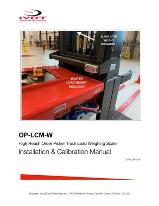
Overview of components
The standard OP-LCM-W SkidWeigh Elite Series onboard weighing scale consist of four main
components:
* Master Digital indicator with Bluetooth module, wiring harness, mounting bracket (Five wires cable)
* Slave digital indicator with Bluetooth module, wiring harness, mounting bracket (Two wires cable)
* Hydraulic pressure transducer with 3 wires cable
* Installation & calibration manual and operator usage instruction
Integrated Visual Data Technology Inc. 3439 Whilabout Terrace, Oakville, Ontario, Canada L6L 0A7
3. !
Operational principal
The OP-LCM-W Series SkidWeigh system operational principal is based
on the hydraulic pressure transducer installed in the vehicle lifting hydraulic
circuit that will automatically activate the proprietary lifted load
“measurement algorithm”. The increase in pressure is converted in an
electronic signal at the sample rate of 16000 readings per measurement
cycle during the lifting operation. The system will automatically calculate
and display lifted load. The OP-LCM-W load weight readout will be clearly
visible to the operator.
Pressure transducer installation
The pressure transducer must be installed in the lifting hydraulic line between the lift control valve and lift
cylinder(s). In majority of cases a T-piece is used to install the pressure transducer in lifting hydraulic line. In some
cases you can install the pressure transducer in the flow divider, drilling and tapping for 1/4”-18 NPT male in spare
plug (if only single or double mast configuration) or in the body of the flow divider. Also, you can drill and tap on any
“larger elbow” that might be available in the hydraulic lifting circuit in the vehicle.
Pressure transducer installation precautions
Before mounting the pressure transducer in the hydraulic lift circuit make
sure that system is pressure free.
There are two ways to do that:
1. Place the forks on the ground in their lowest position and make the
hydraulic system pressure free by tilting the mast forward. The chain(s)
should be slack.
2. Lift the forks and position them on the top of a supporting fixture. Start
lowering the lifting cylinder into its lowest position. Be sure that chains are
slack.
Make sure that that installed pressure transducer will not touch any moving
parts or assembly of the vehicle while in normal operation.
Pressure transducer has 1/4”-18 NPT male thread.
Use thread seal to ensure tight fit.
Swiss Made, Custom Made Pressure Transducer
The OP-LCM-W pressure transducer part number
is IPT-1500must be used with system
Integrated Visual Data Technology Inc. 3439 Whilabout Terrace, Oakville, Ontario, Canada L6L 0A7
T-Piece
Hydraulic Block Divider
4. !
MASTER indicator mounting location
There are many examples of mounting locations for the master indicator that will depend on the vehicle
model. However, additional mounting items such as a flat brackets may be needed to help secure unit.
Choose the most convenient mounting location on the vehicle
body frame (Not to be mounted on moving operator platform).
The system set up, calibration procedure and connection of
the hydraulic pressure transducer is done to the
MASTER Indicator.
SLAVE indicator mounting location
Mount SLAVE indicator in front of the operator on lifting platform. Use plastic ties on molded external
brackets to fasten the indicator.
The slave indicator has only two wires to be
connected to the vehicle power on switch.
The automatic Bluetooth pairing from the master
indictor to the slave will show the operator current
vehicle load capacity in percentage of the
maximum allowed load being handled.
Electrical Connections
The OP-LCM-W SkidWeigh systems operating voltage is from 12 to 55 VDC.
MASTER Indicator
- Orange Wire (+) Ignition switch On position
- Brown Wire (-) Battery negative
- Red Wire, connect to RED wire of the pressure transducer cable
- Black Wire, connect to BLACK wire of the pressure transducer cable
- White Wire, connect to WHITE wire of the pressure transducer cable
SLAVE Indicator
Red Wire, (+) Ignition switch On position
Black Wire, (-) Battery negative
Pressure transducer 3 wires cable must be connected to main cable of the Master indicator.
Integrated Visual Data Technology Inc. 3439 Whilabout Terrace, Oakville, Ontario, Canada L6L 0A7
5. !
Electrical power short circuit protection
All of the SkidWeigh systems are internally short circuit protected with resettable fuse. There is no need to
install external inline fuse in orange wire connected to the ignition switch.
The OP-LCM-W system has a reversal power supply protection.
“Quick test to determine if electrical connections are done right”
Note: SkidWeigh OP-LCM-W calibration function is not done yet at
this stage. This procedure is only to test if electrical connections into
the vehicle is done properly!
After you have connected two wires to the vehicle power and
pressure transducer cable you can “quickly” check the system
operation.
- Lower the forks to the ground
- Turn on vehicle power switch
- Digital LED display will be activated, showing software version and serial number
- Number 8 will be shown on LED display above the MODE digit.
- Lift the empty or loaded forks to increase pressure in lifting cylinder. Number 8 will go off and indicator
will show “some” load on LED display. If the above test is valid the system electrical connections are
done right.
The next procedure will be to calibrate the OP-LCM-M system.
OP-LCM-W weighing function calibration procedure
The OP-LCM-W Series SkidWeigh calibration is automatic and is done by lifting empty forks with
operator on platform just above the ground. The calibration with the known load weight is done with
loaded forks and platform at the highest operational forks height for the particular high reach order
picker truck
Note: The known calibration load weight should be at 24” load centre.
MAKE SURE THAT YOU HAVE A KNOWN LOAD WEIGHT AND KEEP IT NEARBY TO COMPLETE THE
CALIBRATION.
For the best results use minimum calibration load weight of 40% to 70% of the vehicle maximum lifting
capacity of the vehicle at maximum lift height as stated on vehicle name plate.
Use customer floor scale or use a known skid load weight for the RT-LCM-W load weight calibration.
Master Digital Indicator (OP-LCM-W system calibration utilizing two push buttons)
- - Left button “M” is used to enter into calibration mode and to shift to the left to the next digit.
- Right button “Arrow Up” is used to enter numerical increments from 0-9, wrap around.
- Both buttons are used during the system calibration.
Integrated Visual Data Technology Inc. 3439 Whilabout Terrace, Oakville, Ontario, Canada L6L 0A7
6. !
- Buttons can be accessed through two small holes on the cover.
- Use paper clip to activate buttons. Do not push buttons too hard!
- Left most significant digit represents Mode of operation.
- Other five digits represent the load weight readout.
- Note:
- Every time the power is applied the software version will be shown momentarily for a brief moment.
- When forks are lowered to ground LED display will show Mode 8.
- If you make a mistake during the system calibration, turn power ON / OFF and start all over.
Calibration Procedure
Important: If you want the system to show load weight in pounds, use the known load weight in pounds
during the system calibration and enter that value accordingly. The same would apply if you want the
system to show load weight in kilograms then use the known load weight in kilograms and enter that value
into the system accordingly.
Lower the empty forks to the ground
- There should be no hydraulic pressure in lift hydraulic circuit.
- Turn power switch to on position.
- LED display will show software version briefly on the right side and number 8 will be shown in the Mode window.
* For vehicles with cart lower the cart to the ground
MODE Digit 5 Digit 4 Digit 3 Digit 2 Digit 1
Integrated Visual Data Technology Inc. 3439 Whilabout Terrace, Oakville, Ontario, Canada L6L 0A7
Mode Digit Five Digits (Load Weight)
7. !
1. Calibration of empty forks with operator on platform lifted just above
the ground
To initiate calibration press the “M” button (use a paper
clip) and hold it down for approx. 5 seconds.
After approximately five-seconds the Mode display
digit will change from number Mode 8 to Mode 0.
System is ready for automatic zeroing
When LED display is showing Mode 0 lift the empty
forks with operator on the platform just above the
ground.
Within few seconds LED display will go blank and will
show Mode digit 1 and default “0” value in furthest right digit display. (Digit1)
Automatic zeroing is done
2. Calibration of loaded forks with operator lifted to the highest operational
forks height
* Drive your vehicle into the skid load with known
weight at load centre of 24” and lift the load to the
highest operational forks height.
Example:(In our calculation example we will use 1850 pounds as known calibration load weight)
With LED display showing Mode 1 start entering the known calibration load weight value by using Arrow
Up button (increments from 0 to 9) wrap around. Start with Digit 1, least significant digit (in our case input
number “0”) and press momentarily button “M” to advance to next Digit 2. Input number “5” and press
momentarily button “M” to advance to next Digit 3. Keep doing the same until 01850 is entered into the
system.
Integrated Visual Data Technology Inc. 3439 Whilabout Terrace, Oakville, Ontario, Canada L6L 0A7
Paper clip
8. !
Use “M” button to shift from digit 1 to digit 5 and to the Mode 6.
Use Arrow Up buttons to input calibrated known load weight. With each press of the Arrow Up
button you can input digits from 0 to 9, wrap around mode.
Make sure that digit 5 is“0”.
Note: With LED display showing 501850 press “M” button to advance to Mode 6 and lift calibrated
load weight on the forks just above the ground.
The LED display will go “blank” for the moment.
After few seconds LED display will show the calibrated value of 1850.
System load weight calibration is done
* Lower the calibrated load weight to ground
* System is ready to be used.
* Note: To use the load weighing function loaded forks must be lowered to ground and Mode 8 must be
shown on LED display. Lift loaded forks just above the ground to get the load weight.
MODE Digit 5 Digit 4 Digit 3 Digit 2 Digit 1
1 0
2 5
3 8
4 1
5 0
MODE Digit 5 Digit 4 Digit 3 Digit 2 Digit 1
1 8 5 0
Integrated Visual Data Technology Inc. 3439 Whilabout Terrace, Oakville, Ontario, Canada L6L 0A7
9. !
Integrated Visual Data Technology Inc. 3439 Whilabout Terrace, Oakville, Ontario, Canada L6L 0A7
1. Turn on vehicle power switch. With forks lowered to ground SLAVE indicator will show software
version and Mode 8 will be shown on LED display.
WEIGHING PROCEDURE
2. 1. Insert forks into pallet load
2. Make sure that loaded forks are completely on the ground
3. With no hydraulic pressure in lift circuit the LED display will show Mode 8
4. Activate the lift control valve and lift loaded forks just above the ground
5. Mode 8 digit will go off and after few seconds the load weight will be shown on SLAVE indicator
OPERATOR USAGE GUIDE
SLAVE
LOAD WEIGHT
INDICATOR