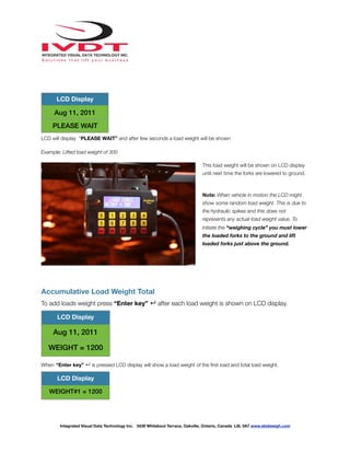
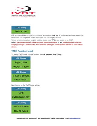
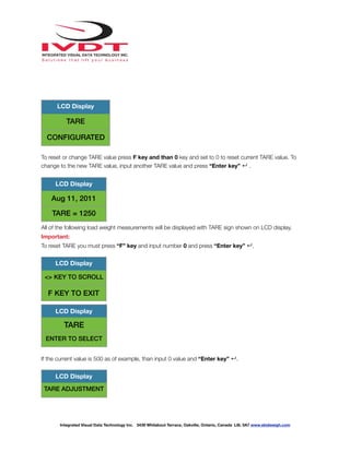
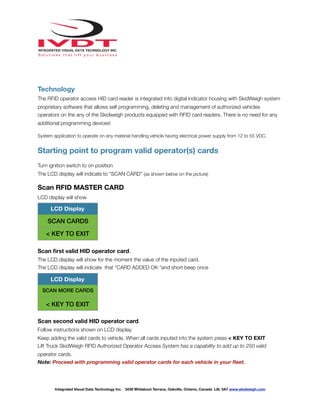
Download to read offline

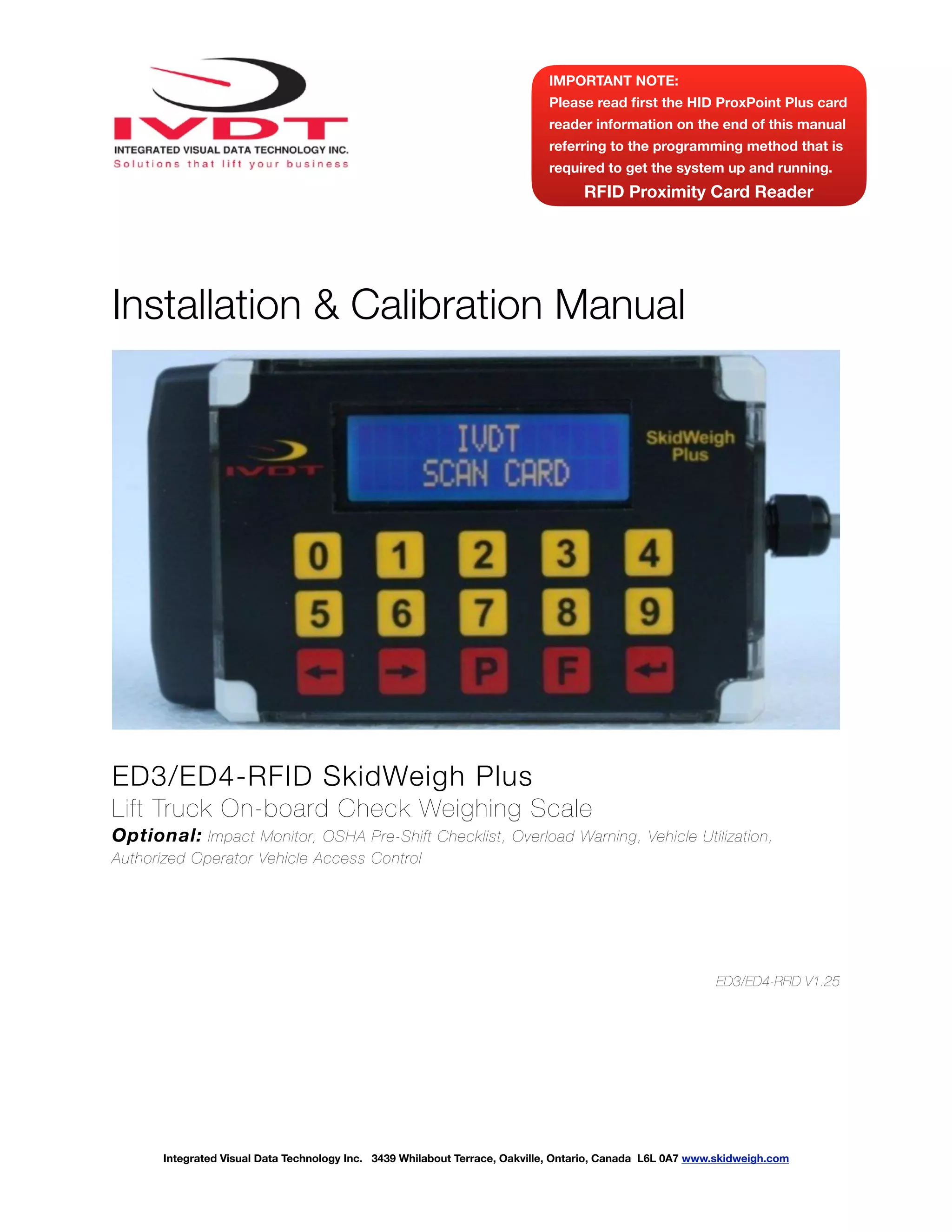


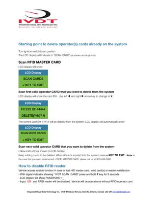


This document provides installation and calibration instructions for the ED3/ED4-RFID SkidWeigh Plus on-board check weighing scale. It includes instructions on installing the pressure transducer, connecting the digital indicator, performing a quick test of the electrical connections, and accessing the administration menu to calibrate the weighing function. Safety precautions and an overview of the system components are also provided.


