Forklift weighing scale with overload warning
•
0 likes•51 views

1) The document provides installation and calibration instructions for the SkidWeigh ED2-SM on-board lift truck scale system. 2) It describes how to install the pressure transducer and digital indicator, make electrical connections, perform a quick test of the system, and calibrate the system by lifting empty and loaded forks. 3) The calibration procedure involves zeroing the scale with empty forks, lifting a pre-weighed test load, and programming the known weight into the system using the paper clip and mode buttons.

Recommended
Recommended
More Related Content
What's hot
What's hot (19)
Similar to Forklift weighing scale with overload warning
Similar to Forklift weighing scale with overload warning (9)
More from Ted Jurca
More from Ted Jurca (20)
Recently uploaded
Recently uploaded (20)
Forklift weighing scale with overload warning
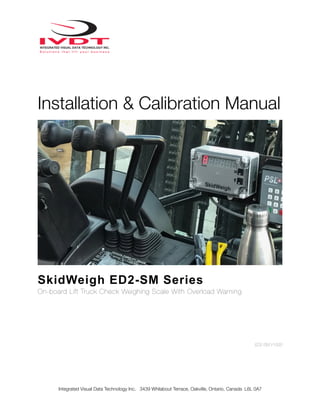
- 1. Installation & Calibration Manual SkidWeigh ED2-SM Series On-board Lift Truck Check Weighing Scale With Overload Warning ED2-SM V1500 Integrated Visual Data Technology Inc. 3439 Whilabout Terrace, Oakville, Ontario, Canada L6L 0A7
- 2. General Installation Guide This SkidWeigh ED2-SM system version V1500, installation & calibration guide describes how to install, calibrate, test and use your lift truck onboard check weighing scale. Following the instructions in this guide will enable you to get your system operating quickly and with ease. In the event that you require additional assistance, please contact technical support below. Integrated Visual Data Technology Inc. 3439 Whilabout Terrace Oakville, Ontario L6L 0A7 Phone: 905-469-0985 Email: support@sidweight.com Web: www.skidweigh.com Safety Always disconnect the vehicle battery before installing SkidWeigh systems. Make sure that the digital indicator, pressure transducer and any other associated cables are securely mounted and do not impede any of the vehicle’s controls. Use care when routing the component cables and where they will be protected. Use commonly accepted install practices for after market industrial vehicle electronic devices. The installation of SkidWeigh systems should only be performed by an acknowledged lift truck technician or other with competent knowledge of electrical and hydraulic systems. Here are two acceptable methods of making a wire connections: 1.Soldering your connections (recommended) 2.Crimp connectors (with the use of the proper crimping tool) Regardless of the method you choose, ensure that the connection is mechanically sound and properly insulated. Use high quality electrical tape and shrink tubing where necessary. This product is connected directly to the vehicle’s ignition switch, 12 to 55 VDC. There is no On-Off switch on the digital indicator. Electro-Magnetic Compatibility CE conformity to EC directive 89/336 (EMC) by application of harmonized standards: Interference stability EN 61000-6-2 and EN 61326-1 interference emit EN 61000-6-3, EN 61326-1 for the pressure transducer. Integrated Visual Data Technology Inc. 3439 Whilabout Terrace, Oakville, Ontario, Canada L6L 0A7
- 3. SkidWeigh ED2-SM Version 1500 Our policy is one of continuous improvement and the information in this document is subject to change without notice. Check that software version displayed on the LED display is reflective of this manual. Overview of Components The standard SkidWeigh ED2-SM check weighing system kit consist of two main components: * Digital indicator with external overload audio warning, wiring harness and anti-vibration mounting bracket. * Hydraulic pressure transducer with 3 wire connection cable. * Installation & calibration manual as well as quick reference operator usage instructions. Operational Principal The SkidWeigh ED2 operational principal is based on mounting a pressure transducer into the vehicles hydraulic lifting circuit between the lift control valve and lifting cylinder(s). Upon usage proprietary software will automatically activate the “weighing cycle algorithm ” when a skid load is lifted just above the ground. The increase in pressure is converted through an electronic signal at the sample rate of 16000 readings per session which is then converted into a load weight reading. Installing the Pressure Transducer The pressure transducer must be installed in the hydraulic lift line between the lift control valve and lift cylinder(s). In some cases you can install the pressure transducer in the flow divider, drilling and tapping for 1/4”-18 NPT male in spare plug or in the body of the flow divider. Also, you can drill and tap on any “larger elbow” that might be available in the hydraulic lift circuit found in vehicles with larger hoses to accommodate larger vehicle lifting capacities. Integrated Visual Data Technology Inc. 3439 Whilabout Terrace, Oakville, Ontario, Canada L6L 0A7 Flow Divider Pressure Transducer Flow Divider T-Piece
- 4. Pressure Transducer Installation Precautions Before installation of the pressure transducer the hydraulic lift circuit must be pressure free. There are two ways to do that: 1. Place the forks on the ground at their lowest position and make sure the hydraulic system pressure is completely free by tilting the mast forward. The chain(s) should be slack. 2. Lift the forks and position them on the top of a supporting fixture. Start lowering the lift cylinder into its lowest position. Ensure that the chain(s) is slack. Make sure that that pressure transducer when installed will not touch or obstruct any assembly or moving parts during operation. The pressure transducer has a 1/4”-18 NPT male thread. Use thread seal to ensure tight fit. Selecting the Mounting Location for the Digital Indicator Use the anti vibration mounting bracket and fasten the digital indicator on the vehicle dashboard, side rail, or over head guard, preferably on the right hand side. There are many examples of mounting locations that will depend on the vehicle model. Each SkidWeigh ED2 kit comes complete with flat universal mounting brackets designed for mounting on the overhead guard. Choose the correct location and make sure that: 1. The Indicator is visible and within reach of the operator. 2. The location does not impede the operator safety entering the vehicle or obstruct operational sight lines Integrated Visual Data Technology Inc. 3439 Whilabout Terrace, Oakville, Ontario, Canada L6L 0A7 Mounting Bracket 3 Wire Pressure Transducer Cable 1/4”-18 NPT male thread
- 5. Electrical Connections - Orange Wire (+) Ignition switch On position (12 to 55 VDC) - Brown Wire (-) Battery negative - Red Wire, connect to RED wire of the pressure transducer cable - Black Wire, connect to BLACK wire of the pressure transducer cable - White Wire, connect to WHITE wire of the pressure transducer cable Pressure transducer cable Pressure transducer 3 wires cable must be connected to the digital indicator cable Electrical power short circuit protection - All of the SkidWeigh systems are internally short circuit protected with resettable fuse. There is no need to install external inline fuse in orange wire connected to the ignition switch. - Automotive 60 V load dump protection - Reversal power supply protection Integrated Visual Data Technology Inc. 3439 Whilabout Terrace, Oakville, Ontario, Canada L6L 0A7 - Orange Wire (+) Ignition switch - Brown Wire (-) Battery negative - Red Wire connect to the RED wire of the pressure transducer cable - Black Wire, connect to BLACK wire of the pressure transducer cable - White Wire, connect to WHITE wire of the pressure transducer cable Pressure Transducer (3 wires) System Power Supply (2 wires) Blue, Green and Blue Wires (Application for Optional Devices)
- 6. ‘Quick Test’ System Check Note: The following ‘Quick Test’ allows the installer to ensure that the both the electrical connections and the installation of the pressure transducer have been performed correctly. Also note the SkidWeigh system is not to be calibrated at this stage. After you have connected electrical power and the pressure transducer cable you can check system operation following these steps. 1. Lower the forks to the ground. 2. Turn on the ignition switch. -The digital LED display will be activated showing the software version and serial number. -The number 8 will be shown on the LED display above the Mode symbol. 3. Lift the forks above the ground with a load to activate the weighing cycle. -Mode 8 will disappear and within a few seconds a load weight will show on the LED display. If the system responds as per the above test the electrical connections and pressure transducer are installed correctly. The load weight will not be accurate as the system has not been calibrated at this point. Hydraulic Accumulators The following applies to lift trucks equipped with hydraulic accumulators. Note: Before installation please ensure that the system was ordered specifically for trucks equipped with hydraulic accumulators. If not please contact technical support for confirmation and or a system with the correct software configuration. Integrated Visual Data Technology Inc. 3439 Whilabout Terrace, Oakville, Ontario, Canada L6L 0A7 Hydraulic Pressure Transducer Mounting Location
- 7. Calibration Procedure The SkidWeigh ED2 calibration cycle is a simple and automatic process that is completed by lifting both empty and loaded forks, and or attachment, and programming the weights into the system. The entire process takes approximately 3 minutes and will require the following to be completed in advance. 1.The paper clip supplied with the system or like. 2. A pre-weighed load in order to set an accurate programming standard into the system. Use an existing floor scale to verify the actual weight or a trusted accurate shipping label. For best results try to secure a load test weight that is 30 - 50% of the maximum lifting capacity. Note: The system can show the load weight in either pounds or kilograms, but not simultaneously. Therefore, calibrate in the preferred measurement unit. Integrated Visual Data Technology Inc. 3439 Whilabout Terrace, Oakville, Ontario, Canada L6L 0A7 Two Button Calibration Mode Toggle Switch Digit Toggle Switch Mode Indicator Zeroing the Empty Forks/Attachment 1. Lower the empty forks to the ground. There should be no hydraulic pressure in the hydraulic lift circuit. 2. Turn the ignition switch to the on position to apply power to the sys- tem. The LED indicator will display the software version and serial number briefly before defaulting to 8 above the Mode Indicator.
- 8. Calibrating the System with a Load Weight 6. With the LED display showing 0 at the far right it is time to enter the known weight secured prior to the calibration process. Using the paper clip enter that weight beginning with Mode 1 through 5, for weights in excess of 9999 lb./kg. If the weight is 9999 or below enter 0 for Mode 5. See the example below. (In our example we will use the known load weight of 4000) First least significant digit “0” Second least significant digit “0” Third least significant digit “0” Forth least significant digit “4” Fifth least enter “0” """ "" Integrated Visual Data Technology Inc. 3439 Whilabout Terrace, Oakville, Ontario, Canada L6L 0A7 3. To begin the calibration process press the M button, using a paper clip and hold for few seconds. Eventually the 8 will change to 0 above the mode indica- tor. System is ready for automatic zeroing. 4. With the indicator showing 0 lift he empty forks approximately 2” - 4” off the ground. With the vehicle stationary do not manipulate the tilt, side shift, or fourth lever function during the lifting process. Activate as you would normally during operation of the vehicle. 5. Within a few seconds of lifting the forks, the LED display will go blank and the digit 1 will show above the Mode Indicator. On the far right side of the display a default 0 will be shown if the system is being calibrated for the first time. If a recalibration is being performed then the digit programmed from the prior ses- sion will show instead. Automatic Zeroing is Complete.
- 9. Entering Overload Warning (ED2-SM SkidWeigh Series) If the SkidWeigh ED2 Series system utilizes the SM (Overload) function) than the system will automatically default to MODE 7 when the loaded forks are lowered to the ground. Using the “M” and “Up Arrow” buttons enter the overload weight value for your application similar to the process when calibrating the system with a load weight except the MODE 7 digit remains throughout this operation. Once the last digit has been entered MODE 7 will disappear. The overload weight value is now successfully stored into the system memory. Example: Below is an example of a desired overload weight of 4850. As per the calibration process for value 9999 or less enter 0 for the 5th digit. System is calibrated for both weight and overload warning Mode Digit 5 Digit 4 Digit 3 Digit 2 Digit 1 7 0 4 8 5 0 Integrated Visual Data Technology Inc. 3439 Whilabout Terrace, Oakville, Ontario, Canada L6L 0A7 7. With the system at Mode 5, after entering all digits, drive into the secured palleted load. Once the loads is secure on the lift truck make sure that all pressure is out of the hydraulic system by lowering the forks till the lift chains show slack. 8. Using the paper clip press the M button to advance to Mode 6. 9. Lift the known weight 2” - 4” off the ground similar to the zeroing process. With the vehicle stationary do not manipulate the tilt, side shift, or fourth lever function during the lifting process. Activate lift control lever and lift load as you would normally during operation of the vehicle. After few seconds the LED display will show calibrated load weight. System is now calibrated.
- 10. Integrated Visual Data Technology Inc. 3439 Whilabout Terrace, Oakville, Ontario, Canada L6L 0A7 PAGE ! OF !1 2 Operator Usage Guide ED2 SkidWeigh Series ED2 SkidWeigh Series • Turn on ignition switch • With LED display will show software version for the moment and mode will indicate number 8 which is the starting point to initiate load weight cycle (Loaded forks must be lowered to ground, no pressure in lift hydraulic circuit for the system to show Mode 8) Insert the forks into the pallet or product to be weighed • Lower the loaded forks to the ground. • With LED display showing number 8 in Mode, lift load just above the ground • Do not manipulate the tilt, side shifter or move vehicle during the weighing cycle • Lift the load approx. 2” off the ground using the hydraulic lift lever same as during normal usage. Do not use lift lever by lifting load “slowly”. • Within few seconds load weight will be indicated on LED display. Note: During the normal vehicle usage the LED display might show “0” or some other load weight which is due to the hydraulic “spikes”. To initiate a load weighing cycle you must lower loaded forks to the ground and LED must show number 8 in Mode window. Load Add Button Accumulative Load Weight Total and Print Onboard Printer
- 11. Integrated Visual Data Technology Inc. 3439 Whilabout Terrace, Oakville, Ontario, Canada L6L 0A7 PAGE ! OF ! VER. FLS3-22 2 INTEGRATED VISUAL DATA TECHNOLOGY INC. 3439 Whilabout Terrace, Oakville, Ontario, L6L 0A7 Canada Phone: 905-469-0985 Fax: 905-825-9494 skidweigh.com Accumulative Load Weight Function • With LED display showing load weight, press “Black button” to start accumulating loads • With last load weight lifted and shown on LED display by pressing “RED button” all individual loads and total load weight will be shown. If the onboard Bluetooth printer is used than all individual load weights and total will be printed Overload Indication • The ED2SkidWeigh series with optional overload warning will automatically show on LED display the overload load value and display will “flash”. The audio / visual warning will be activated to warn the operator of such condition. To stop the overload visual / audio overload warning operator must lower the load to the ground. Two Independent Weighing Channels • Use external mounted switch to utilize the two independent weighing channels function. Example: Standard forks and long forks weighing application Note: Weighing channel one is shown as a Mode 8 and second is shown as Mode 82. Electric Pallet Truck Weighing Function (ED2-EP Skidweigh Series) • Turn on power switch (ED2-EP only). Insert forks into the load and lower it to the ground. The LED display must show Mode 8. • Activate and hold vehicle lift control until lifting cylinder is automatically stopped • Weighing cycle will start, the LED display will go “blank” for the moment and load weight will be shown. As soon the load weight is shown the lift motor motion control is disabled • Lift cylinder motion control will go back to normal operational mode Note: During normal operation where weighing function is not required turn the indicator power switch ON /OFF to off position. (The ED2E-EP system will be turned off) Two Weighing Channels Switch Channel 1 (showing Mode 8 on LED display) Channel 2 (showing Mode 82 on LED display) Power On / Off Switch ED2 V1500