Download to read offline


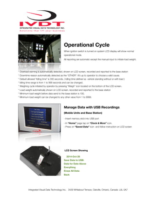
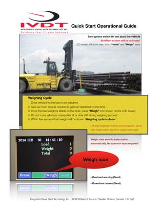

This document provides instructions for installing, calibrating, and using the SkidFleet on-board check weighing and utilization system. It describes how to install the pressure transducer and digital indicator, set up vehicle ID, downtime reasons, date/time, and calibrate the load weighing function. Calibration involves lifting the empty forks and a known test weight to set zero point and full scale readings, and entering an overload value. Contact customer support is provided for additional assistance.


